manuals.online logo
Brands
  1. Home
  2. •
  3. Brands
  4. •
  5. Channel Safety Systems
  6. •
  7. Lighting Equipment
  8. •
  9. Channel Safety Systems Grove User manual

Channel Safety Systems Grove User manual

CHANNEL SAFETY SYSTEMS t: 0845 884 7000 | w: www.channelsafety.co.uk
INSTRUCTION MANUAL - Issue 1 - 02/2014 | 1
INSTRUCTION MANUAL
CHANNEL SAFETY SYSTEMS t: 0845 884 7000
Peterseld Business Park f: 0845 884 6000
Bedford Road
Peterseld
Hampshire e: sales@channelsafety.co.uk
GU32 3QA w: www.channelsafety.co.uk
LED Twin Spot
from Channel Safety Systems
L
E
D
T
i
S
t
CHANNEL SAFETY SYSTEMS t: 0845 884 7000 | w: www.channelsafety.co.uk
INSTRUCTION MANUAL - Issue 1 - 02/2014 | 2
Horizontal Adjustment Screw
Vertical Adjustment Screw
INSTALLATION
All Installations should be carried out by a competent electrician.
1. Lay tting on its back and remove lid.
2. Remove and discard packing pieces.
3. Fit unit securely to wall, unit may be mounted in any orientation.
4. Connect a 230V AC supply to the‘L E N’ terminal block on the circuit board.
5. Connect the battery to the PCB terminals ensuring correct polarity is observed. (Red +ve, Black –ve).
Follow for the IP65 Version: - Follow for the IP20 Version: -
Fault nding
Monitoring LED’s –The left hand LED indicates that the unit has a
230vAC supply and is charging the battery, if it is not illuminated, then the
mains 230v supply has failed, or the battery is faulty/disconnected. The right
hand LED indicates the lamps (LED clusters) are connected to the unit.
Unit Not Meeting Required Emergency Period
May require cycling. Discharge, then recharge for at least 24 hours. Re-test.
Battery may need replacing if emergency duration still not met.
To be regularly tested in accordance with BS5266-1:2005
1. Position the lamps to the required position and use the locking
screws to secure the lamps in the chosen position.
2. Please note if the unit is tted directly to a wall and downward
light is required, the unit must be mounted with the lamps at the
top.
3. The unit will not illuminate in emergency mode until the mains
has been switched on and subsequently failed.
4. Operational check – Restore the A.C. supply for 30 minutes and
then remove. The lamps should illuminate for at least 30 seconds.
5. Switch on the mains supply and note that the indicator LED’s
have illuminated, proving that the unit is operational, the lamp
continuity is OK and that the battery is being charged.
6. The unit has deep discharge protection and this should
operate when the battery voltage falls to approx. 8V DC, whilst in
the Emergency Mode.
1. The unit will not illuminate in emergency mode until the mains
has been switched on and subsequently failed.
2. Operational check – restore the A.C. supply for 30 minutes and
then remove. The lamps should illuminate for at least 30 seconds.
3. Switch on the mains supply and note that the indicator LED’s
have illuminated, proving that the unit is operational, the lamp
continuity is OK and that the battery is being charged.
4. The unit has deep discharge protection and this should
operate when the battery voltage falls to approx. 8V DC, whilst in
the Emergency Mode.
CHANNEL SAFETY SYSTEMS t: 0845 884 7000 | w: www.channelsafety.co.uk
INSTRUCTION MANUAL - Issue 1 - 02/2014 | 3
TESTING
Recommended Routine Test Procedure
The following test is designed to ensure the continued protection of your premises and occupants. Because of the possibility of a failure of the normal light-
ing supply occurring shortly after a period of testing, all tests should, whenever possible, be undertaken at times of least risk, e.g. during daylight hours.
Once A Day
Visual inspection of battery charge led.
Once A Month
Each unit should be energised from it’s battery for adequate time to ensure, by simulation of a failure of the normal lighting supply, the emergency mode is
functioning correctly.
Once Each Year
All units should be placed into emergency mode and checked that the duration provided by the battery meets the specied time period.
INSTRUCTION MANUAL
CHANNEL SAFETY SYSTEMS t: 0845 884 7000
Peterseld Business Park f: 0845 884 6000
Bedford Road
Peterseld
Hampshire e: sales@channelsafety.co.uk
GU32 3QA w: www.channelsafety.co.uk

This manual suits for next models

1

Other Channel Safety Systems Lighting Equipment manuals

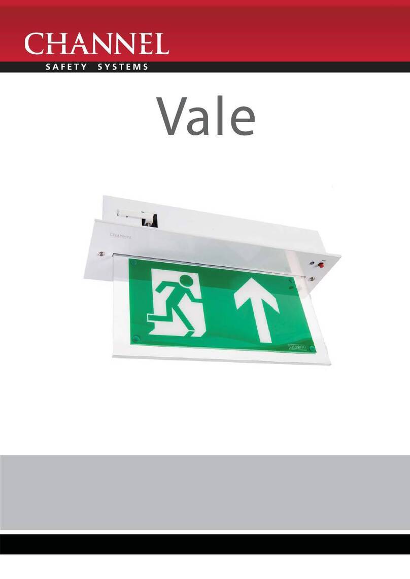
Channel Safety Systems Vale User manual

Channel Safety Systems

Channel Safety Systems Vale User manual

Channel Safety Systems Wyvern User manual

Channel Safety Systems

Channel Safety Systems Wyvern User manual

Channel Safety Systems alpine User manual

Channel Safety Systems

Channel Safety Systems alpine User manual

Channel Safety Systems EntriTech Series Specification sheet

Channel Safety Systems

Channel Safety Systems EntriTech Series Specification sheet

Popular Lighting Equipment manuals by other brands

Douglas Lighting Controls Dialog WIR-3110 user manual

Douglas Lighting Controls

Douglas Lighting Controls Dialog WIR-3110 user manual

fatboy ROCKCOCO manual

fatboy

fatboy ROCKCOCO manual

Hayward POOL Rx Socket owner's manual

Hayward

Hayward POOL Rx Socket owner's manual

SubC Imaging AQUOREA Mk2 LED user manual

SubC Imaging

SubC Imaging AQUOREA Mk2 LED user manual

Narex CR LED 20 Original operating manual

Narex

Narex CR LED 20 Original operating manual

Cineroid Metal Series user manual

Cineroid

Cineroid Metal Series user manual

Hayward 3478 PLDBL3 owner's manual

Hayward

Hayward 3478 PLDBL3 owner's manual

Daintree GE Current UltraMax GED80MCC/Z2P1500 installation guide

Daintree

Daintree GE Current UltraMax GED80MCC/Z2P1500 installation guide

Light-ink OUTDOOR-PAR 7 HEXA manual

Light-ink

Light-ink OUTDOOR-PAR 7 HEXA manual

Code DL10490BK1-4 Use and care guide

Code

Code DL10490BK1-4 Use and care guide

JUST NORMLICHT V8 S Assembly and instruction manual

JUST NORMLICHT

JUST NORMLICHT V8 S Assembly and instruction manual

American DJ Comscan LED User instructions

American DJ

American DJ Comscan LED User instructions

Miboxer S2-B quick start guide

Miboxer

Miboxer S2-B quick start guide

Flash butrym LED PAR 56 user manual

Flash butrym

Flash butrym LED PAR 56 user manual

g-lites Moon Light user manual

g-lites

g-lites Moon Light user manual

Equinox Systems SIGMA EQLA09 user manual

Equinox Systems

Equinox Systems SIGMA EQLA09 user manual

Code 3 XP9500 Installation & operation manual

Code 3

Code 3 XP9500 Installation & operation manual

Lampo IP66 user manual

Lampo

Lampo IP66 user manual

manuals.online logo
manuals.online logoBrands
  • About & Mission
  • Contact us
  • Privacy Policy
  • Terms and Conditions

Copyright 2025 Manuals.Online. All Rights Reserved.