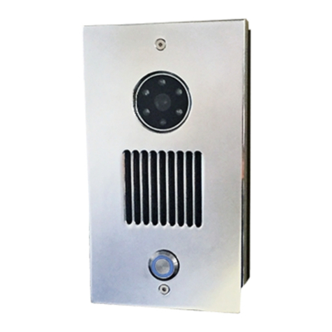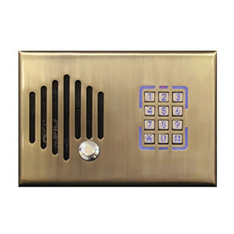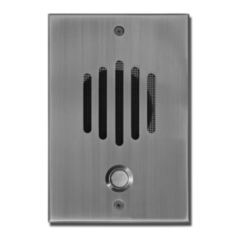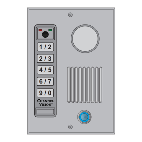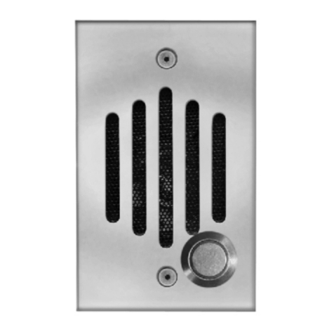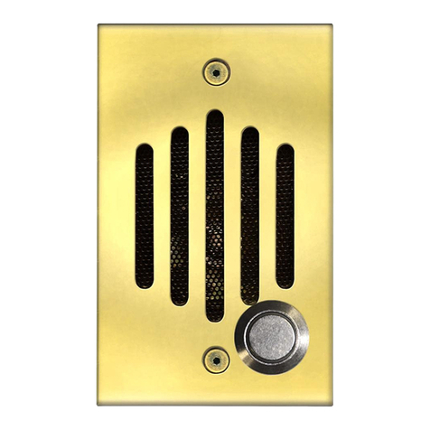
Speaker:
Size (mm): 50
Depth (in): 1.5
Impedance: 8 Ohms
Power Peak (W): 0.2
Frequency Range: 500 Hz - 4.5 kHz
Dimensions:
3 1
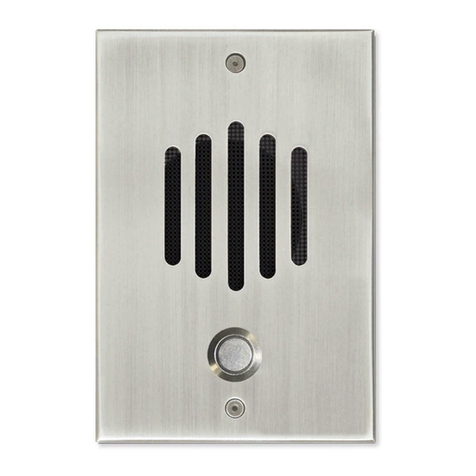
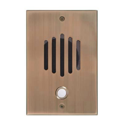
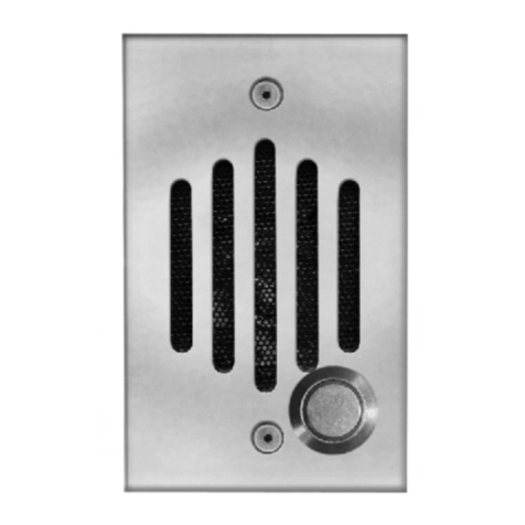
DP-Series plate only: 6 ½” (L) x 4 / ” (W) x / ” (D)
8 4
3 3
DP-Series assembly: 6 ½” (L) x 4 / ” (W) x 1 / ” (D)
8 4
PCB Surface: Waterproof silicon protected
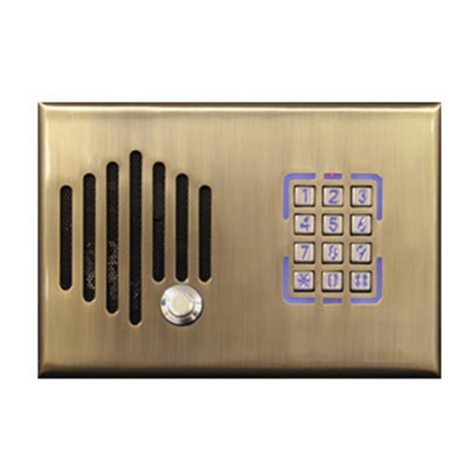
DP Doorplate Surface: Solid Brass, Coated & Protected
Button Color: Blue
Button Power: 12vDC 150mA
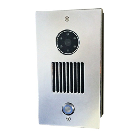
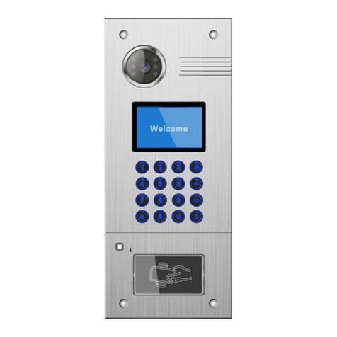
Color Camera: (SI-6xxx & SI-6xxxP only)
Signal System: NTSC
Total Pixels 1020 (H) x 508 (V) 520K
Effective Pixels 976 (H) x 494 (V) 480K
Image Sensor 1/3” 960H Super HD CCD II (Sony)
Lens Pinhole, 5.5mm
Signal Processing Digital
Scanning System 2:1 Interlace
Sync System Internal
Scanning Frequency 59.94Hz (VD)
Resolution 700 TV Lines
S/N Ratio More than 50dB (AGC Off)
Video Output 1.0 Vpp Composite (75Ω)
Min Illumination 0.0002 Lux@Sense-up
OSD Yes
Shutter Automatic
Power Consumption 12vDC 300mA total with button and camera
(Power Supply model 5015PS, included)
Operating Temperature 14° - 122° Fahrenheit
*Maintenance of Door Station plate
Channel Vision recommends a light coating of vegetable oil on the
surface and edging of the DP Doorplate for long lasting shine and
protection. Quarterly to monthly maintenance is recommended.
Specifications subject to change without notice.
SI-xxxxC
500ft.
max
The diagram below shows how to connect the SI-xxxxC to Channel Vision’s
CAT5 Whole-House Intercom system. When the button is pressed on the
SI-xxxxC the ST-2000 Intercom Stations will generate a door chime.
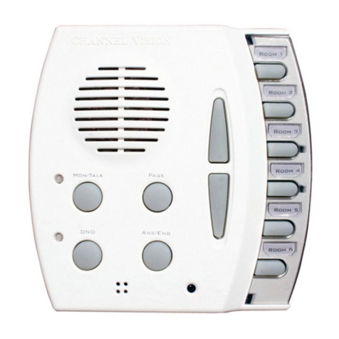
Pressing Answer/End will open communication with the SI-xxxxC. Model SI-
6xxxC includes a color camera, and SI-0xxxC includes no camera.
Channel Vision Compatible
(SI-xxxx )
CAT5 Intercom
C
Specifications
P-0930
PRO
CH AN NE L
TM
VI S I O N
Model
P-0930 Whole-House Intercom
Page Out
Page Trigger
IR
Emitters +15VDC
Power
Link
In
Link
Out
Hub
A
B
C
DRoom 1 Room 2 Room 3 Room 4 Room 5 Room 6
ST-2000
Press here to
answer door
These terminals can be
used to connect a ST-C5IDS
Door Strike Relay Module Room 1
Room 2
Room 3
Room 4
Room 5
Room 6
Monitor
DND Answer/End
Page
Camera Power
To Monitor or
Video Distribution
Video
Connector
BNC
Share camera
power with
button
Installation:
h
Using CAT5 wire, connect the P-0930 to the 110 connector on the SI
h
doorplate using 110 punch tool or Channel Vision model J-110-Tool or
1014.
If necessary, attach the camera’s video output to a coax cable
h
(RG-59 or RG-6).
If necessary, cut the connector off of the end of the power supply and
h
splice in an extension using crimp-on connectors.
Install a compatible mounting box at the desired locations:
DP-Rbox-II, DP-Rbox-III flush mount boxes, DP-9001 surface mount
box, or DP-9002 surface mount box.
10 11
