10
Troubleshooting:
11
Specifications: (typical at 25 degrees C)
Amplifier:
Power input: 24VDC
Output power: 50 Watts/ch RMS into 6 ohms @ <10% THD
Frequency Response: 20-20kHz (+/-3dB)
Signal to Noise Ratio: >85dB
Input Sensitivity: 500mVRMS
Auto On Threshold: 10mVRMS
Wireless Receiver:
Input Voltage: 6-30 VDC
THD+N: 0.7% Max
S/N Ratio: 80 dB
Audio Latency: 3.8 ms
Operating Frequency: 2400 MHz
Data Rate: 1.152 Mbps
Audio Sampling Rate: 48 kHz
Channels: 8 (User Selectable)
RX Sensitivity: -85 dBm
Image Rejection: 47 dBc
Audio Output Level: 2.6 Vpp
Audio Output Impedance: 16 Ohm
Frequency Response: 20-20kHz +/- 3dB
Adjacent Channel Rejection: >45 dB
Storage Temperature: -40 to +85º C
Operating temperature: 0 to +55º C
Specifications subject to change without notice
Note: This equipment has been tested and found to comply with the limits for a
Class B digital device, pursuant to part 15 of the FCC Rules. These limits are
designed to provide reasonable protection against harmful interference in a
residential installation. This equipment generates, uses and can radiate radio
frequency energy and, if not installed and used in accordance with the
instructions, may cause harmful interference to radio communications. However,
there is no guarantee that interference will not occur in a particular installation. If
this equipment does cause harmful interference to radio or television reception,
which can be determined by turning the equipment off and on, the user is
encouraged to try to correct the interference by one or more of the following
measures:
!Reorient or relocate the receiving antenna.
!Increase the separation between the equipment and receiver.
!Connect the equipment into an outlet on a circuit different from that to which
the receiver is connected.
!Consult the dealer or an experienced radio/TV technician for help.
!Modifications not expressly approved by the manufacturer could void the
user's authority to operated the equipment under FCC rules.
FOR HOME OR OFFICE USE FOR HOME OR OFFICE USE
Channel Vision WA-350Channel Vision WA-350
Tested To ComplyTested To Comply
With FCC StandardsWith FCC Standards
FOR HOME OR OFFICE USE FOR HOME OR OFFICE USE
Channel Vision WA-351Channel Vision WA-351
Tested To ComplyTested To Comply
With FCC StandardsWith FCC Standards
Problem: Hum in System
Troubleshooting: Plug all parts of the system into the same outlet to see if
the hum goes away.
Cause: The different components in the system are connected to different
electrical grounds. This forces electrical currents to find alternate paths to
ground causing an audible 60Hz hum.
Solution: Plug products into an electrical circuit with a common ground. Lift
the ground with a ground lifting plug.
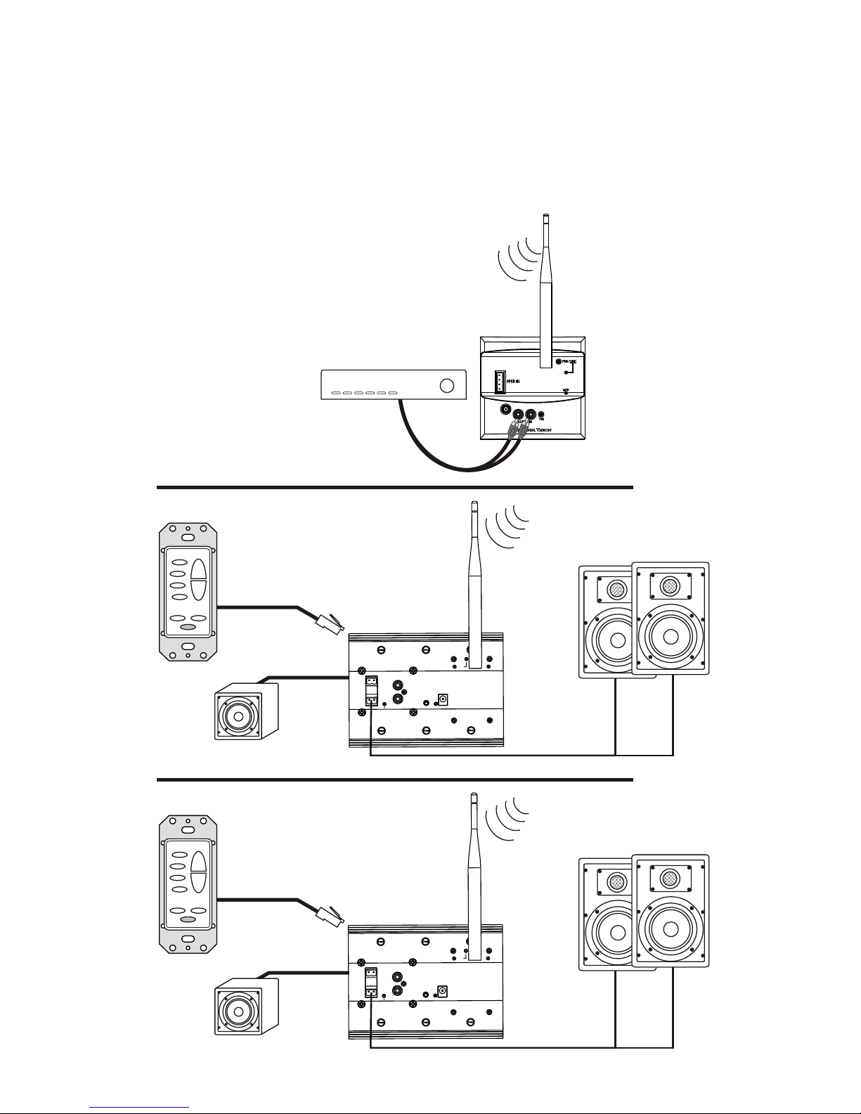
Problem: Transmitter is not linking with the receiver.
Troubleshooting: Make sure you are linking compatible models (WA-320
with WA-360). Check if pwr/lnk LED indicator on the transmitter is turning
amber and that the signal LED is lit.
Cause: Link button on WA-350 is not being pressed quickly enough. Review
the linking procedure in this manual. Please note that a transmitter and
receiver will remain paired even after being unplugged. This allows you to
complete the linking process before placing the receiver in it’s final location.
Solution: Press the Link button on the WA-320 and confirm that the pwr/lnk
LED turns amber. Within 6 seconds, press the Link button on the WA-350.
Problem: Can’t link to the transmitter, or audio is cutting out.
Troubleshooting: Check the source, is it sending a signal? Consider setting
the jumpers on the transmitter (WA-320/WA-321) to the “disable audio-
sensing” position during setup procedure (see the Rear Panel Features and
Connections section). This will ensure that the transmitter will not mute
during pauses or very quiet passages.
Cause: Either there is no audio going into the transmitter, or the audio is very
quiet which is causing the transmitter to mute.
Solution: Use a known good audio source. If you can’t find any other
problems, try using a different source component even if you think your audio
source is OK.