Channel Vision WA-321 User manual

WA-321
WA-361
1-to-Many Wireless Audio Transmitter
1-to-Many Wireless Audio Receiver
9

23
The WA-321 1-to-Many Wireless Audio Transmitter and WA-361 1-to-Many
Wireless Audio Receiver make it possible to create a distributed audio
system without running wires from one room to another. The WA-321 can
accept either line level or speaker level audio, making it easy to distribute
signals to the rear speakers of a surround sound system. The transmitter
can link to multiple receivers allowing music to be distributed to multiple
locations simultaneously. To avoid interference, the WA-321 can broadcast
over 8 different transmission channels.
Features:
!Wirelessly transmits audio up to 300ft.
!Line-level, Speaker-level, or CAT-5 Audio System inputs (WA-321)
!Standard Line-level audio outputs (WA-361)
!8 transmission channels
!Easy installation and linking
WA-321
WA-361
Antenna... Transmits RF signal to the receiver.
Antenna... Receives RF signal from the transmitter.
Speaker-Level Input... Accepts speaker-level
input from an amplifier.
Power/Link LED... Indicates power and link
activity.
Power LED... Indicates power.
Link Button... Press to begin the linking process.
Press the link button on the receiver to complete
the process.
Link Button... Press to complete the linking
process after the link button has been pressed on
the transmitter.
Reset Button... Press to reset transmitter.
Reset Button... Press to reset receiver.
Power In... Connect power supply here.
Audio In... Connect audio source here.
Audio Out... Connect audio amplifier here.
Signal LED... Illuminates when signal
is present.
Link LED... Indicates when receiver is linked to a
transmitter.
IMPORTANT SAFETY INSTRUCTIONS
1. Read these instructions.
2. Keep these instructions for future reference.
3. Heed all warnings.
4. Follow all instructions.
5. Do not use this device near water.
6. Clean only with a dry cloth.
7 Do not block any ventilation openings. Install in accordance with these
instructions.
8. Do not install near any heat sources such as radiators, heat registers,
stoves, or other apparatus (including amplifiers) that produce heat.
9. This apparatus must not be exposed to dripping or splashing and no
objects filled with liquids, such as vases, shall be placed on the apparatus.
10. Protect the power cord from being walked on or pinched particularly at
plugs, convenience receptacles, and the point where they exit from the
apparatus.
12. Unplug this apparatus during lightning storms or when unused for long
periods of time.
13.
Warning: To reduce the risk of electric shock, do not remove the cover (or
back), no user serviceable parts inside, refer servicing to qualified service
personnel.
CAUTION
RISK OF ELECTRIC SHOCK
DO NOT OPEN
RISK OF ELECTRIC SHOCK
DO NOT OPEN !
Accessories & Complementary Products (sold separately)
A0240... 2-channel 40 Watt amplifier. It can be
used to power a small 1-room audio system or
integrated with Channel Vision’s A0302 to
provide supplemental power to low power
distributed audio systems.
In-wall and In-ceiling Speakers... Channel
Vision offers a full line of premium in-wall and
in-ceiling speakers. These speakers are
perfect for whole-house music or home theater
applications.
VC-302... Impedance Matching Volume Control
The VC-302 is an impedance matching volume
control with an IR receiver knockout. The
knockout allows Channel Vision’s
IR-2400 to be integrated with the volume
control for applications that require IR
repeating. The VC-302 comes with white,
ivory, and almond knobs and face plates to
easily match other wall plates in the room.
Linking the WA-361 to the WA-321
The WA-361 and WA-321 operate on a 1-to-Many broadcast basis. The WA-361
must be “Linked” to a specific WA-321 transmitter prior to the first use. Once
linked they will maintain their paired status even if a power loss occurs. The
“RST” button can be used to release a linked receiver from its transmitter.
Press and hold the Link button for 3 seconds
to begin the linking process
.
The green PWR/LINK LED will turn orange.
Press the link button on the receiver within 6
seconds to complete the process.
Note: The green PWR/LINK LED will blink
until the receiver has been linked.
WA-321
WA-361
5
4

WA-361 Installation
The WA-361 can be installed in the wall using a standard 1-gang junction box
or low-voltage mounting ring. For surface mounted or free-standing
applications, it can be installed in the back box provided.
Follow the simple illustrations below.
Standard
1-gang ring
or j-box
(not included)
Mounting Plate
(included)
Hang the WA-361 from the center tab on the mounting plate.
Tighten screw in bottom secure unit to mounting plate.
Remove the metal mounting hardware.
Use the same 4 screws to attached
the back box.
WA-361
In-Wall Installation
Free-Standing Installation
WA-361
WA-321 Installation
The WA-321 can be installed in the wall using a standard 2-gang junction box
or low-voltage mounting ring. For surface mounted or free-standing
applications, it can be installed in the back box provided.
Follow the simple illustrations below.
Hang the WA-321 from the center tab on the mounting plate.
Tighten screw in bottom secure unit to mounting plate.
Remove the metal mounting hardware.
Use the same 4 screws
to attached the back box.
In-Wall Installation
Free-Standing Installation
WA-321
Standard
2-gang ring
or j-box
(not included)
Mounting Plate
(included)
WA-321
7
6

Using the WA-321 & WA-361 in a Home Theater
The WA-321 can accept the left/right surround speaker outputs from a home
theater amplifier and transmit the signal to the WA-361. The WA-361 can then
output the signal to a small amplifier like the A0240 which powers the
speakers. The volume level of the surround speakers will be raised and
lowered by the volume control of the home theater amplifier.
Front Left
Surround
Left
Speaker Wire
Speaker Wire
Front Right
Surround
Right
WA-321
WA-361
A0240
Center
Surround
Speaker
Outputs
Home Theater
Amplifier
Surround speaker are powered
by the A0240, but the volume is
controlled by the home theater
amplifier.
Amplifier
Using the WA-321 & WA-361 for Distributed Audio
These wireless audio products make it easy to transmit audio from one room
to another. Connect any standard audio component to the input connectors of
the WA-321 in Room 1, and use the RCA outputs of WA-361 receivers to feed
amplifiers in several different rooms. If a fixed gain amplifier is used (such as
the A0240), a volume control like the VC-302 will be needed to adjust the
volume level in the remote rooms.
Room 1
Audio Source
WA-321
Room 2
Speaker Wire
WA-361 VC-302
A0240
Room 3
Speaker Wire
WA-361 VC-302
A0240
9
8

10 11
Specifications: (typical at 25 degrees C)
Transmit and Receive:
Input Voltage: 6-30 VDC
THD+N: 0.7% Max
S/N Ratio: 80 dB
Audio Latency: 3.8 ms
Operating Frequency: 2400 MHz
Data Rate: 1.152 Mbps
Audio Sampling Rate: 48 kHz
Channels: 8 (User Selectable)
Transmit:
Transmission Power: 8.5 dB (9.5dB Max)
Modulation Type: GFSK
Channel Spacing: 9 MHz
Max. Audio Input: 2.6 Vpp
Input Impedance: 20 kOhm
Max. Speaker Level In: 100 Watts RMS
Receive:
RX Sensitivity: -85 dBm
Image Rejection: 47 dBc
Audio Output Level: 2.6 Vpp
Audio Output Impedance: 16 Ohm
Frequency Response: 20-20kHz +/- 3dB
Adjacent Channel Rejection: >45 dB
Specifications subject to change without notice
Rear Panel Features and Connections:
110 Connector... Allows connection to a Crescendo or
®
A-BUS hub.
Screw Terminals... Provide power input and
audio output connections.
J5 & J6 RCA/Screw Terminal Jumpers...
When using , set to pins 1&2.
When using , set to pins 2&3.
screw terminals
RCA outputs
Power in
WA-361
WA-321
Audio Out
+V
Gnd
Gnd
Right +
Left +
Input Switch... Place in the down position when using speaker-
level inputs and up position when using the line-level inputs.
J2 & J5 RCA/110 Jumpers... When using RCA inputs, set to
pins 1&2. When using 110 connector, set to pins 2&3.
J8 & J9 Audio Sense Jumpers... Set to pins 1&2 to enable
audio-sensing. Set to pins 2&3 to disable audio-sensing.
A-BUS is a registered trademark of LeisureTech Electronics Pty Ltd
Using the WA-321 & WA-361 in a Crescendo CAT-5 Audio System
The WA-321 can accept and input signal from Channel Vision’s Crescendo
CAT-5 Audio System and transmit the signal to the WA-361.
Amp-Link
Channel Vision
R
L/S Line Out
Amp-Link
Channel Vision
R
L/S Line Out
di b l
1 4 CAT5 Au o Distri ution Modu e
Rir d( equ e )
Pwr
o e
(O tio
p nal)
Status
ys emS t
ys emS t
Input
Local
Inpt
u
Z ne 1o Ze 2
on Ze
on 3 Zne 4
oE p n io
x a s n
Outp t
u
L c l
oa
Priority Sl
igna
LREm tt r
i e s
PRO
HN E
CANL
M
T
I O N
VIS
HN E
CANL
I O N
VISM
T
IR
x
M
T
CHANE L SNN VIIO
Mde 2014
o l P-
Source
CHANNEL VIS ION
Pwr
Source
CHANNEL VIS ION
Pwr
Room 1 Room 3 A0313A0301
P-2014
Line level inputs
IR emitters
A0313
Audio Source
Use 110 connector
on rear panel.
WA-321
Room 4
Wirelessly Distributed
Speaker Wire
WA-361
VC-302
A0240

10 11
Specifications: (typical at 25 degrees C)
Transmit and Receive:
Input Voltage: 6-30 VDC
THD+N: 0.7% Max
S/N Ratio: 80 dB
Audio Latency: 3.8 ms
Operating Frequency: 2400 MHz
Data Rate: 1.152 Mbps
Audio Sampling Rate: 48 kHz
Channels: 8 (User Selectable)
Transmit:
Transmission Power: 8.5 dB (9.5dB Max)
Modulation Type: GFSK
Channel Spacing: 9 MHz
Max. Audio Input: 2.6 Vpp
Input Impedance: 20 kOhm
Max. Speaker Level In: 100 Watts RMS
Receive:
RX Sensitivity: -85 dBm
Image Rejection: 47 dBc
Audio Output Level: 2.6 Vpp
Audio Output Impedance: 16 Ohm
Frequency Response: 20-20kHz +/- 3dB
Adjacent Channel Rejection: >45 dB
Specifications subject to change without notice
Rear Panel Features and Connections:
110 Connector... Allows connection to a Crescendo or
®
A-BUS hub.
Screw Terminals... Provide power input and
audio output connections.
J5 & J6 RCA/Screw Terminal Jumpers...
When using , set to pins 1&2.
When using , set to pins 2&3.
screw terminals
RCA outputs
Power in
WA-361
WA-321
Audio Out
+V
Gnd
Gnd
Right +
Left +
Input Switch... Place in the down position when using speaker-
level inputs and up position when using the line-level inputs.
J2 & J5 RCA/110 Jumpers... When using RCA inputs, set to
pins 1&2. When using 110 connector, set to pins 2&3.
J8 & J9 Audio Sense Jumpers... Set to pins 1&2 to enable
audio-sensing. Set to pins 2&3 to disable audio-sensing.
A-BUS is a registered trademark of LeisureTech Electronics Pty Ltd
Using the WA-321 & WA-361 in a Crescendo CAT-5 Audio System
The WA-321 can accept and input signal from Channel Vision’s Crescendo
CAT-5 Audio System and transmit the signal to the WA-361.
Amp-Link
Channel Vision
R
L/S Line Out
Amp-Link
Channel Vision
R
L/S Line Out
1 4 CAT5 Audi Di ib Modul
o str ution e
(Required)
Power
(Optional)
S a st tu
m
Syste
y m
S ste
u
Inp t
o l
Lca
Input
Zone 1 Zone 2 Zone 3 Zone 4 Expan io
sn
Output
Local
Priority Sig aln
LREmitt rs
e
R
P O
CH N N E
AL
TM
VI S I O N
CH N N E
AL
VI S I O NTM
IR
x
M
T
HANEL N
NV
CIS I O
de 2014Mo l P-
Source
CHANNEL VIS ION
Pwr
Source
CHANNEL VIS ION
Pwr
Room 1 Room 3 A0313A0301
P-2014
Line level inputs
IR emitters
A0313
Audio Source
Use 110 connector
on rear panel.
WA-321
Room 4
Wirelessly Distributed
Speaker Wire
WA-361
VC-302
A0240

Channel Vision Technology will repair or replace any defect in
material or workmanship which occurs during normal use of this
product with new or rebuilt parts, free of charge in the USA, for two
years from the date of original purchase. This is a no hassle warranty
with no mail in warranty card needed. This warranty does not cover
damages in shipment, failures caused by other products not supplied
by Channel Vision Technology, or failures due to accident, misuse,
abuse, or alteration of the equipment. This warranty is extended only
to the original purchaser, and a purchase receipt, invoice, or other
proof of original purchase date will be required before warranty
repairs are provided.
Mail in service can be obtained during the warranty period by calling
(800) 840-0288 toll free. A Return Authorization number must be
obtained in advance and can be marked on the outside of the shipping
carton.
This warranty gives you specific legal rights and you may have other
rights (which vary from state to state). If a problem with this product
develops during or after the warranty period, please contact Channel
Vision Technology, your dealer or any factory-authorized service
center.
500-227 rev B
www . c h a n n e l v i s i o n.com
234 Fischer Avenue, Costa Mesa, California 92626 USA
(714)424-6500 (800)840-0288 (714)424-6510 fax
email: [email protected]
Other manuals for WA-321
1
This manual suits for next models
1
Other Channel Vision Receiver manuals

Channel Vision
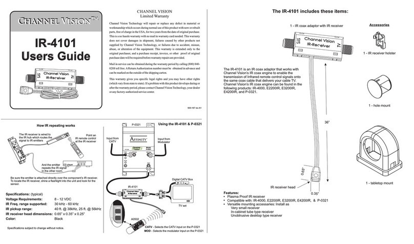
Channel Vision IR Reciever IR-4101 User manual

Channel Vision
Channel Vision IR-2400 User manual

Channel Vision
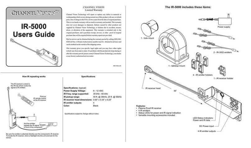
Channel Vision IR-5000 User manual

Channel Vision
Channel Vision WA-350 User manual

Channel Vision
Channel Vision ARIA Audio A0326 User manual

Channel Vision
Channel Vision A0325 User manual

Channel Vision
Channel Vision IR-2400 User manual

Channel Vision
Channel Vision Aria Audio A0327 User manual

Channel Vision
Channel Vision WA-321 User manual

Channel Vision
Channel Vision IR Receiver IR-5000 User manual