Page 9
Page 8
Step 5: Verify the station operates correctly.
IMPORTANT:if the station is not operating as described below, see Troubleshooting on
page 13 to resolve the error before continuing.
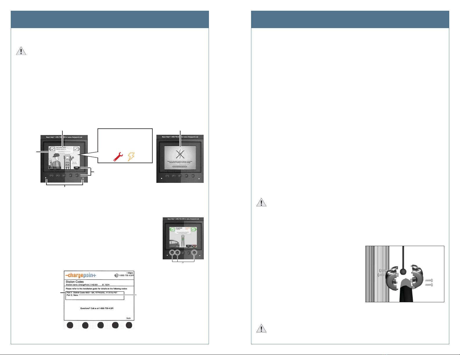
a) When the station is powered on, you should see:
• The instructional video, and no error messages.
• The status icon for each port displaying a green check mark.
Neither of the two error LEDs light up (for some errors, these LEDs are solid or
blinking red).
NOTE: If the station does not power up, check that the head assembly’s blue
rectangular connector is properly seated onto the terminal block.
For some errors, this top banner
displays an error message instead
of station information
Under
normal
conditions,
the station
displays the
instructional
video
For some errors, one or both error LED(s)
will appear solid or blinking red
The status icon for each port
should display a green check
mark. If these icons appear,
the port (or station) has an
error:
Choose a menu option
by pressing the button
below it
In some cases, a static
error message fills the
entire display
b) Even if the station’s display and LEDs show no indication of an error, always check
the station codes to confirm that no errors exist. To display station codes:
• Activate the Service Menu by simultaneously pressing
and holding the two left most buttons and the right most
button for two seconds.
• Press the station button immediately below the “HELP”
menu option.
• Press the station button immediately below the “DOWN”
menu option to highlight “Station Codes”.
• Press SELECT.
This port is
displaying
a station
code
This port is
not
displaying
a station
code
If you see a station code, you must resolve or report the error before leaving the
installation site. Station codes are described on pages 13 to 17.
Simultaneously press and
hold these three buttons
for two seconds to displa
the Service Menu on an
unactivated station
Install the New Head Assembly Install the New Head Assembly
c) Use your ChargePoint card to authorize a charging session. Make sure that both plug
holsters unlock and that the station displays instructions on how to plug into the
vehicle.
d) Ensure the station is receiving an adequate LAN signal to allow it to communicate
with other nearby station(s) in the same radio group. HOW? OR DO THEY JUST
NEED TO MAKE SURE THEY DON’T HAVE AN ERROR 204?
NOTE: Stations must be located within 150 line of sight of a gateway station with no
obstructions.
e) GATEWAY STATIONS only: Ensure the station is receiving an adequate signal
strength from the cellular network:
• Activate the Service Menu as described on the previous page (b).
• Press the station button immediately below the “Basic Mode” menu option.
• Press the station button immediately below the “DOWN” menu option to
highlight “Display last measured RSSI”.
The strength of the signal should be A, B, or C. If the network signal is Grade D and
a better network signal is available on the other type of modem, change modems
by choosing: Basic mode > Change modem technology (CDMA or GSM). If the signal
strength is either weak (D) or not available for both modems, arrange for cellular
repeaters to be installed near the installation site.
If you have performed the above steps, and the station operates as described and no errors
exist, continue with the installation. If any of the above conditions are not met, resolve the
error before continuing (see Troubleshooting on page 13).
Step 6: Install the Cable Clamps.
IMPORTANT:Do not unwrap the retractor’s ropes until they are securely attached to the
charging cable.
a) Locate the bead at the end of the retractor rope.
b) Uncoil the charging cable by removing the plastic wrap, then gently extending it all
the way out, away from the station. Rotate the plug as necessary to remove any
twists or kinks. Locate the tape that marks the position where the clamp attaches to
the cable.
c) Insert the bead inside the clamp, then
snap the opposite side of the clamp into
place.
d) Secure the two sides of the clamp
together by inserting the four screws and
tightening them securely using a Phillips
screwdriver.
e) Pull down on the rope and remove the
rope from its wrapper. When the rope is
unwrapped, it retracts into the top cap.
f) Repeat the above steps for the other charging cable (if applicable). If installing a
single port station, allow the left (unused) rope fully retract into the top cap.
IMPORTANT:Check that the charging cable extends and retracts fully and smoothly. If
it doesn’t, see page 18.


