manuals.online logo
Brands
  1. Home
  2. •
  3. Brands
  4. •
  5. ChargePoint
  6. •
  7. Batteries Charger
  8. •
  9. ChargePoint CPE200 User manual

ChargePoint CPE200 User manual

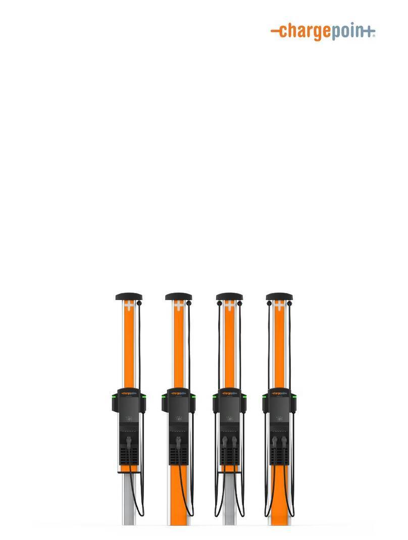
CPE200
DC Fast Charging Station
Installation Guide
May 8, 2018
Part Number 75-001211-01 Rev 3
ii
Copyright and trademarks
©2013-2018 ChargePoint, Inc. All rights reserved. This material is protected by the copyright laws of the United
States and other countries. It may not be modified, reproduced or distributed without the prior, express
written consent of ChargePoint, Inc. CHARGEPOINT is a U.S. and European Union registered trademark and
service mark of ChargePoint, Inc. and cannot be used without the prior written consent of ChargePoint.
No accuracy guarantee
Commercially reasonable efforts were made to ensure that the specifications and other information in this
manual are accurate and complete at the time of its publication. However, the specifications and other
information in this manual are subject to change at any time without prior notice.
Warranty information and disclaimer
The Warranty you received with your Charging Station is subject to certain exceptions and exclusions. For
example, your use of, or modification to, the ChargePoint® Charging Station in a manner in which the
ChargePoint® Charging Station is not intended to be used or modified will void the limited warranty. You
should review your warranty and become familiar with the terms thereof. Other than any such limited
warranty, the ChargePoint products are provided "AS IS", and ChargePoint, Inc. and its distributors expressly
disclaim all implied warranties, including any warranty of design, merchantability, fitness for a particular
purposes and non-infringement, to the maximum extent permitted by law.
Limitation of liability
CHARGEPOINT IS NOT LIABLE FOR ANY INDIRECT, INCIDENTAL, SPECIAL, PUNITIVE OR CONSEQUENTIAL
DAMAGES, INCLUDING WITHOUT LIMITATION LOST PROFITS, LOST BUSINESS, LOST DATA, LOSS OF USE,
OR COST OF COVER INCURRED BY YOU ARISING OUT OF OR RELATED TO YOUR PURCHASE OR USE OF,
OR INABILITY TO USE, THE CHARGING STATION, UNDER ANY THEORY OF LIABILITY, WHETHER IN AN
ACTION IN CONTRACT, STRICT LIABILITY, TORT (INCLUDING NEGLIGENCE) OR OTHER LEGAL OR
EQUITABLE THEORY, EVEN IF CHARGEPOINT KNEW OR SHOULD HAVE KNOWN OF THE POSSIBILITY OF
SUCH DAMAGES. IN ANY EVENT, THE CUMULATIVE LIABILITY OF CHARGEPOINT FOR ALL CLAIMS
WHATSOEVER RELATED TO THE CHARGING STATION WILL NOT EXCEED THE PRICE YOU PAID FOR THE
CHARGING STATION. THE LIMITATIONS SET FORTH HEREIN ARE INTENDED TO LIMIT THE LIABILITY OF
CHARGEPOINT AND SHALL APPLY NOTWITHSTANDING ANY FAILURE OF ESSENTIAL PURPOSE OF ANY
LIMITED REMEDY.
ChargePoint, Inc. 
254 East Hacienda Avenue
Campbell, CA 95008 USA

US and Canada: +1-877-850-4562

[email protected]
iii
Table des matières
Vue d'ensemble . . . . . . . . . . . . . . . . . . . . . . . . . . . . . . . . . . . . . . . . . . . 1
Déroulement de l'installation . . . . . . . . . . . . . . . . . . . . . . . . . . . . . . . 2
Spécifications . . . . . . . . . . . . . . . . . . . . . . . . . . . . . . . . . . . . . . . . . . . .3
Exigences relatives à l'installation . . . . . . . . . . . . . . . . . . . . . . . . . . . . 5
Sécurité . . . . . . . . . . . . . . . . . . . . . . . . . . . . . . . . . . . . . . . . . . . . . . . . . 5
Mise à la terre . . . . . . . . . . . . . . . . . . . . . . . . . . . . . . . . . . . . . . . . . . . .6
Site . . . . . . . . . . . . . . . . . . . . . . . . . . . . . . . . . . . . . . . . . . . . . . . . . . . . .6
Alimentation électrique . . . . . . . . . . . . . . . . . . . . . . . . . . . . . . . . . . . 7
Environnement . . . . . . . . . . . . . . . . . . . . . . . . . . . . . . . . . . . . . . . . . . . 7
Outils du prestataire . . . . . . . . . . . . . . . . . . . . . . . . . . . . . . . . . . . . . .7
Préparation de la coulée . . . . . . . . . . . . . . . . . . . . . . . . . . . . . . . . . . . .9
Préparation d'une nouvelle coulée . . . . . . . . . . . . . . . . . . . . . . . . . .9
Outils pour une nouvelle coulée . . . . . . . . . . . . . . . . . . . . . . . . .9
Installation dans une nouvelle coulée de béton . . . . . . . . . . .11
Préparation d'une surface existante . . . . . . . . . . . . . . . . . . . . . . . . 13
Outils pour une coulée existante . . . . . . . . . . . . . . . . . . . . . . . 13
Installation dans une coulée de béton existante . . . . . . . . . . 14
Installation . . . . . . . . . . . . . . . . . . . . . . . . . . . . . . . . . . . . . . . . . . . . . . 17
Outils requis pour l'installation de la borne . . . . . . . . . . . . . . . . . 18
Transport . . . . . . . . . . . . . . . . . . . . . . . . . . . . . . . . . . . . . . . . . . . . . . . 18
Contrôle . . . . . . . . . . . . . . . . . . . . . . . . . . . . . . . . . . . . . . . . . . . . . . . 18
Retrait de l'emballage . . . . . . . . . . . . . . . . . . . . . . . . . . . . . . . . . . . . 19
Vérification du contenu . . . . . . . . . . . . . . . . . . . . . . . . . . . . . . . . . . 19
Positionnement vertical . . . . . . . . . . . . . . . . . . . . . . . . . . . . . . . . . 20
Retrait des panneaux de radiateur . . . . . . . . . . . . . . . . . . . . . . . . 20
Retrait des boulons de transport . . . . . . . . . . . . . . . . . . . . . . . 21
Retrait du radiateur . . . . . . . . . . . . . . . . . . . . . . . . . . . . . . . . . . 21
Retrait de la plaque de base . . . . . . . . . . . . . . . . . . . . . . . . . . . . . .23
Sécurisation de la coulée . . . . . . . . . . . . . . . . . . . . . . . . . . . . . . . . .23
Retrait du panneau . . . . . . . . . . . . . . . . . . . . . . . . . . . . . . . . . . . . . .24
Débranchement du panneau . . . . . . . . . . . . . . . . . . . . . . . . . . . . . .25
Retrait des panneaux de service . . . . . . . . . . . . . . . . . . . . . . .26
Table des matières
iv
Câblage . . . . . . . . . . . . . . . . . . . . . . . . . . . . . . . . . . . . . . . . . . . . . . . . . 27
Installation du conduit et du câblage . . . . . . . . . . . . . . . . . . . . . .28
Câblage souterrain . . . . . . . . . . . . . . . . . . . . . . . . . . . . . . . . . . .28
Câblage au sol . . . . . . . . . . . . . . . . . . . . . . . . . . . . . . . . . . . . . . .29
Connexion des câbles . . . . . . . . . . . . . . . . . . . . . . . . . . . . . . . . . . . 30
Vérification du câblage . . . . . . . . . . . . . . . . . . . . . . . . . . . . . . . 31
Réassemblage . . . . . . . . . . . . . . . . . . . . . . . . . . . . . . . . . . . . . . . . . . . 33
Retrait des sangles . . . . . . . . . . . . . . . . . . . . . . . . . . . . . . . . . . . . . .34
Remontage des caches . . . . . . . . . . . . . . . . . . . . . . . . . . . . . . . . . .34
Remontage du radiateur . . . . . . . . . . . . . . . . . . . . . . . . . . . . . . . . .35
Fixation des panneaux . . . . . . . . . . . . . . . . . . . . . . . . . . . . . . . . . . .36
Remontage du câblage de panneau . . . . . . . . . . . . . . . . . . . . . . .38
Fixation du panneau . . . . . . . . . . . . . . . . . . . . . . . . . . . . . . . . .39
Vérification de la connectivité . . . . . . . . . . . . . . . . . . . . . . . . . . . . . . 41
Fonctionnalité du tableau de bord . . . . . . . . . . . . . . . . . . . . . . . . . 41
Activation . . . . . . . . . . . . . . . . . . . . . . . . . . . . . . . . . . . . . . . . . . . . . . .43
Localisation . . . . . . . . . . . . . . . . . . . . . . . . . . . . . . . . . . . . . . . . . . . .43
Compléter la liste de contrôle post-installation . . . . . . . . . . . . . 44
1
1
Overview
The ChargePoint CPE200 Fast Charger (CPE200) offers DC fast charging for all EVs equipped with
DC fast charging. This section provides the following information:
+Workflow
+Specifications
Charging plugs
Plug holders
Cooling assembly
Message display and indicators
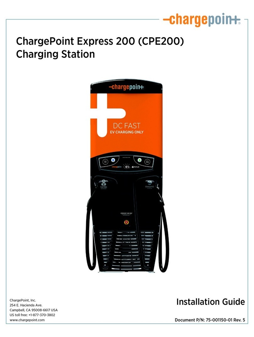
ChargePoint Express 200
2
Workflow
The following chart shows the installation flow process for the CPE200.
Overview
3
Specifications
Table 1 Electrical input
Input power 52 kW @ 3-phase
Input voltage, charging 400/230 V, 415/240 V ±10%
Input current 78 A
Input frequency 50 Hz 5%
Standard wiring 3-phase, 5-wire (L1, L2, L3, N, Ground)
Table 2 Electrical output
Maximum output power 50 kW (@400–500 V)
Output voltage 200–500 V DC
Output current 125 A max
Table 3 Functional interfaces
Connector types CHAdeMO, CCS2
Cable length 3.8 metres
LCD display 2 line OLED display
Plug-in detection No selection of plug required
Auto-detects which plug is connected
Table 4 Safety and operational ratings
Enclosure rating Type 3R, IP 65
Surge protection 6 kV @ 3,000 A
In geographic areas subject to frequent
thunderstorms, supplemental surge
protection at the service panel is
recommended.
Efficiency >92%
Power factor >0.99
Cooling Liquid-cooled
Operating altitude 1,828 metres
Operating temperature -35 to 50°C
Storage temperature -20 to 45°C
High-altitude operating
temperature
1,800–2,400 m: -35 to 40°C
Output power derating may apply
Operating humidity Up to 95% @ +50°C non-condensing
Terminal block Temperature rating: 75°C
Tightening torque: 3.5 Nm
Wire size: 21–34 mm2
Table 5 Dimensions and weights
Dimensions 2,000 (H) x 750 (W) x 330 (D) mm
Installation footprint 580 (W) x 270 (D) mm
Weight 165 kg
Shipping weight 200 kg
ChargePoint Express 200
4
5
2
Installation requirements
The CPE200 Fast Charger must be installed only by ChargePoint-certified installers and in
accordance with all local and national codes and standards.
Important
If you are using the CPE200 Adapter, please see the
CPE200 Adapter Guide.
Important
Installing the CPE200 Fast Charger by any person
other than a ChargePoint-certified installer voids the
warranty and ChargePoint is not responsible for any
malfunction.
This chapter provides various requirements that should be observed before installation.
+Safety
+Grounding
+Site
+Electrical power
+Environmental
+Contractor tools and materials
Safety
You must comply with the following safety requirements:
+Meet local building and safety codes, and International Electrotechnical Commission (IEC),
as applicable.
+Shut off all voltage sources and verify absence of voltage when installing the power supply.
+Use a forklift or crane to lift the 330 kg weight of the CPE200 in its horizontal orientation to
prevent injury.
ChargePoint Express 200
6
Grounding
The CPE200 must be connected to a grounded, metal, permanent wiring system. An equipment-
grounding conductor must be run with circuit conductors and connected to equipment-grounding
terminal or lead on battery charger.
An insulated grounding conductor that is identical in size, insulation material and thickness to the
grounded and ungrounded branch-circuit supply conductors except that it is green with or
without one or more yellow stripes is to be installed as part of the branch circuit that supplies the
unit or system. This grounding conductor must be grounded to earth at the service equipment or,
when supplied by a separately derived system, at the supply transformer.
Site
Important
Do not install the CPE200 Fast Charger kerbside on
a roadway, in a commercial car repair facility or
within 6 metres of an outdoor fuel dispensing device
to reduce potential risk of explosion.
+The CPE200 Fast Charger is fastened to a prepared concrete pad using four anchor bolts.
The pad must be level and flat and be 20 MPa or greater. The concrete pad must support the
size and weight of the CPE200 Fast Charger and comply with all applicable codes. See the
Preparing the pad chapter for instructions.
+Refer to your Site Survey Plan to ensure that site meets the following requirements:
–Mobile coverage
–Electrical panel capacity
–Installation location for each station
+The CPE200 charging cables can reach up to 3.2 metres. Ensure that the charging plugs can
easily reach cars’ charging ports without effort or strain on either end.
+Install the CPE200 Fast Charger at the end of a stall parking space or island with pull-
through capability.
+If installed at the end of a parking space, the CPE200 Fast Charger can either be centred at
the end of the parking space or positioned up to 305 metres to the left as you face the rear
of the space.
Electrical power
Caution
The CPE200 Fast Charger must be installed and
serviced only by qualified electrical personnel.
+The CPE200 accommodates service wiring through a conduit installed either underground
or above ground. Above-ground conduit is to be used only in locations such as a parking
garage where it is impossible to accommodate service wiring from underground.
+Ensure to comply to the national, regional and local regulatory electrical requirements.
Installation requirements
7
+Always connect the CPE200 to the equipment-grounding conductor of your electricity
supply.
+Observe local regulations regarding wiring different circuits in the same conduit, including
the Ethernet link if used. In general, all conductors occupying the same conduit shall have an
insulation rating equal to at least the maximum circuit voltage applied to any conductor
within the conduit.
+Use 90°C copper wire and 21-34 mm2wiring.
Environmental
The CPE200 Fast Charger is IP65 compliant. The conduit must be appropriately sealed to maintain
IP65 rating. The CPE200 Fast Charger may be installed and operated at elevations of maximum
2,400 metres. Ensure that the maximum operating temperature does not exceed the figure listed
in the following table.
Operating altitude 1,828 metres
Operating temperature -35 to 50°C
Storage temperature -35 to 50°C
High-altitude operating
temperature
1,800–2,400 m: -35 to 40°C
Operating humidity Up to 95% @ +50°C non-condensing
Contractor tools and materials
You will need tools and materials to install the mounting template and the stations:
+Tools and materials for a new pad
+Tools and materials for an existing pad
+Tools to install the station
ChargePoint Express 200
8
9
3
Preparing the pad
You can mount the CPE200 onto a newly-poured concrete pad or to an existing concrete surface
(e.g. a parking garage):
+Preparing a new pad
+Preparing an existing surface
Important
Always check local codes or consult an engineer to
ensure that the installation complies with all
applicable codes. 

The guidelines described here are the minimum
requirements. You may need to increase the
dimensions of the concrete pad depending on local
regulations or soil conditions.
Preparing a new pad
The CPE200 is bolted directly to the concrete pad. If you plan to upgrade from the CPE200 to the
CPE250 charging station, refer to the CPE200 Adapter Guide.
Tools and materials for a new pad
+Concrete to build the mounting pad, 20 MPa minimum
+40 mm conduit as required, terminating in a threaded female coupling flush with the top
surface of the concrete
For convenience and as an option, you can purchase the following items from ChargePoint:
+CPE200 Concrete Mount Kit (PN CPE200T-CCM), which includes all mounting hardware
+Prefabricated plywood template (PN CPE200T-BT)
ChargePoint Express 200
10
If you are not purchasing the above items from ChargePoint, you need the following items:
+Bolt installation template that you can download from 
http://www.chargepoint.com. See Figure 1.
Note
Ensure that the PDF version is accurate by printing it
at 100% scale on A3 paper, and then verifying at
least one dimension.
+Plywood suitable for a template
+12 galvanised washers
+12 x M16 heavy galvanised hex nuts (DH rated)
+4 x M16 x 300 mm hot-dipped galvanised headless bolts
+40 mm conduit to the concrete pad
+8 x 16 mm ID heavy washers
+Service disconnect switches (as required)
Figure 1 Bolt installation template sample
Preparing the pad
11
Installing in new concrete
Important
Check local codes or consult an engineer to ensure
that the installation complies with all applicable
codes.
1. Verify that the site is suitable for a CPE200 installation. Confirm that there is adequate
clearance and that the CPE200 can be properly positioned so that the cable can reach the
charge ports of any EV parked in the space.
2. Trench and excavate an opening for the concrete pad that measures at least 1 m wide x
850 mm long (front to back) and 650 mm deep (below grade). The concrete pad must be
reinforced with rebar.
3. Build the concrete form.
4. Run 40 mm conduit from disconnect. Thread a nipple or short section of conduit into the
coupling. This will determine the position of the plywood template and mounting bolts.
5. Add rebar to reinforce the concrete pad. Dowel to adjacent concrete if applicable.
6. Place the ChargePoint prefabricated plywood template into the opening.
Note
If you have not purchased one from ChargePoint,
you can download a template from
http://www.chargepoint.com.
ChargePoint Express 200
12
7. Install two nuts with one washer captured between them onto each of the four bolts. 
Lock them together so the washer is 25 mm from the bottom of the bolt.
25 mm
35 mm
Concrete
surface
8. Insert the bolts through the template and thread the remaining nuts onto the top end of the
bolts. Position the nuts so the bolts extend 35 mm above the concrete.
Note
Make sure that the studs do not protrude more than
40 mm including the thickness and height of the
plywood template. Removing and replacing the fan
will be impossible when the protrusion is more than
40 mm.
9. Cover the nuts and the exposed end of the bolts with tape to protect them from
contamination.
10. Pour the concrete into the form.
11. Immediately afterwards, rotate the bolts to draw the concrete into the threads. Make sure that
they are vertical. Ensure correct alignment and that the top 35 mm of the bolts remains
exposed.
12. If pouring an above grade pad, form a faux curb with score line 150 mm from edge.
Score line Conduit coupling
Preparing the pad
13
13. When the concrete is firm, remove the upper nuts and template. Finish smoothing the top
surface of the concrete pad.
14. Allow the concrete to cure for at least 48 hours to reach full strength.
The concrete pad is now ready to install the CPE200. See the Installing chapter.
Preparing an existing surface
You can mount the CPE200 directly on an existing concrete surface, such as a parking garage.
Check that the top surface of the concrete is perfectly flat and level and bolt the CPE200 station
directly on the concrete surface. If you plan to upgrade from the CPE200 to the CPE250 charging
station, refer to the CPE200 Adapter Guide.
The conduit is brought into the rear of the CPE200 via the concrete surface.
Note
To safely mount the CPE200, the concrete must be
at least 200 mm thick. At this thickness, all
mounting bolts must be positioned at least 500 mm
from the front and rear edges and at least 60 cm
from the side edges.
Tools and materials for an existing pad
+Hammer drill with 13 mm chuck
+20 mm x 450 mm masonry drill bit for concrete
+4 x M16 x 300 galvanised threaded rods
+4 x M16 galvanised hex nuts
+4 x M16 galvanised washers
+Consumable materials for each station
–1 cartridge concrete repair and anchoring epoxy to attach anchor bolts into drilled holes
–Mixing nozzles for epoxy concrete adhesive for concrete with extra mixing nozzles to
accommodate delays of over three minutes when applying epoxy
–1 standard epoxy caulking gun
–1can compressed air duster
ChargePoint Express 200
14
–20 mm x 450 mm masonry drill bit, 13 mm shank, 250 mm drill depth, 305 mm length
overall to drill 20 mm holes
–Nylon loop-handle brush, 19 mm brush diameter, 76 mm length brush, 216 mm length
overall to remove dust from drilled holes
–Push-on round cap, fits 16–17 mm OD, 13 mm inside height
Installing in existing concrete
Important
If installing into any reinforced or pre-tensioned
concrete, you must X-ray the area to ensure that you
are not drilling through any rebar.
1. Make 16 mm diameter holes in the ChargePoint prefabricated plywood template at the bolt
locations.
Note
If you have not purchased one from ChargePoint,
you can download a template from 
http://www.chargepoint.com. See Figure 1 for a
template sample.
2. Use the template guide to mark the hole locations in the concrete.
3. Drill four 20 mm diameter holes into the concrete. Ensure that the bolts protrude 35 mm
above the concrete surface.
35 mm
175 mm
Concrete surface
4. Remove all dust from the holes using a brush and compressed air or a vacuum. Insert the rod
to confirm the correct depth.
5. Insert the bolts into the plywood template with nuts on top of the template.
Preparing the pad
15
6. Fill the four holes with epoxy to 76 mm below the top.
Note
Take note of the cure time to make sure you can
insert and position the bolts before the epoxy sets.
7. Insert the bolts into the holes. Ensure the bolts protrude 35 mm above the concrete.
Note
Inserting the threaded bolts displaces the epoxy,
causing it to fill the holes to grade level. If the epoxy
is below grade level, you can add more after the next
step.
8. Loosen the nuts and rotate the bolts to ensure the epoxy penetrates the threads. Avoid getting
epoxy into the above-grade threads.
9. Tighten the nuts again to ensure the bolts are plumb.
10. Verify that the bolts protrude 35 mm above the concrete.
Note
Make sure that the bolts do not protrude more than
40 mm including the thickness and height of the
plywood template. Removing and replacing the fan
will be impossible when the protrusion is more than
40 mm.
11. Allow the epoxy to cure completely before applying any load. Check the cure time on the
manufacturer’s data sheet.
You are now ready to install the CPE200. See the Installing chapter.
ChargePoint Express 200
16

Other ChargePoint Batteries Charger manuals

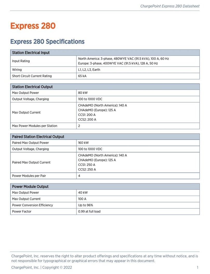
ChargePoint Express 280 Guide

ChargePoint

ChargePoint Express 280 Guide

ChargePoint Express 250 Operating instructions

ChargePoint

ChargePoint Express 250 Operating instructions

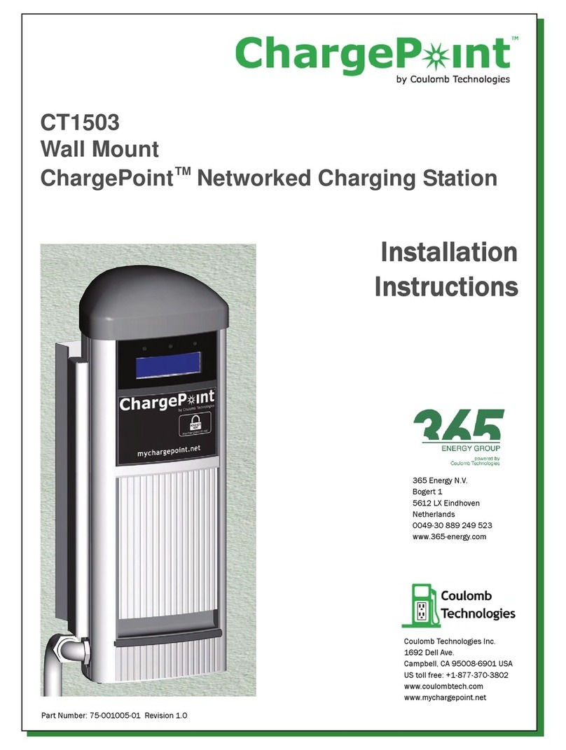
ChargePoint CT1503 User manual

ChargePoint

ChargePoint CT1503 User manual

ChargePoint SM-A127FZBVEUA User manual

ChargePoint

ChargePoint SM-A127FZBVEUA User manual

ChargePoint Home Flex User manual

ChargePoint

ChargePoint Home Flex User manual

ChargePoint CPF25 User manual

ChargePoint

ChargePoint CPF25 User manual

ChargePoint Express 250 Operating instructions

ChargePoint

ChargePoint Express 250 Operating instructions

ChargePoint CT1000 series User manual

ChargePoint

ChargePoint CT1000 series User manual

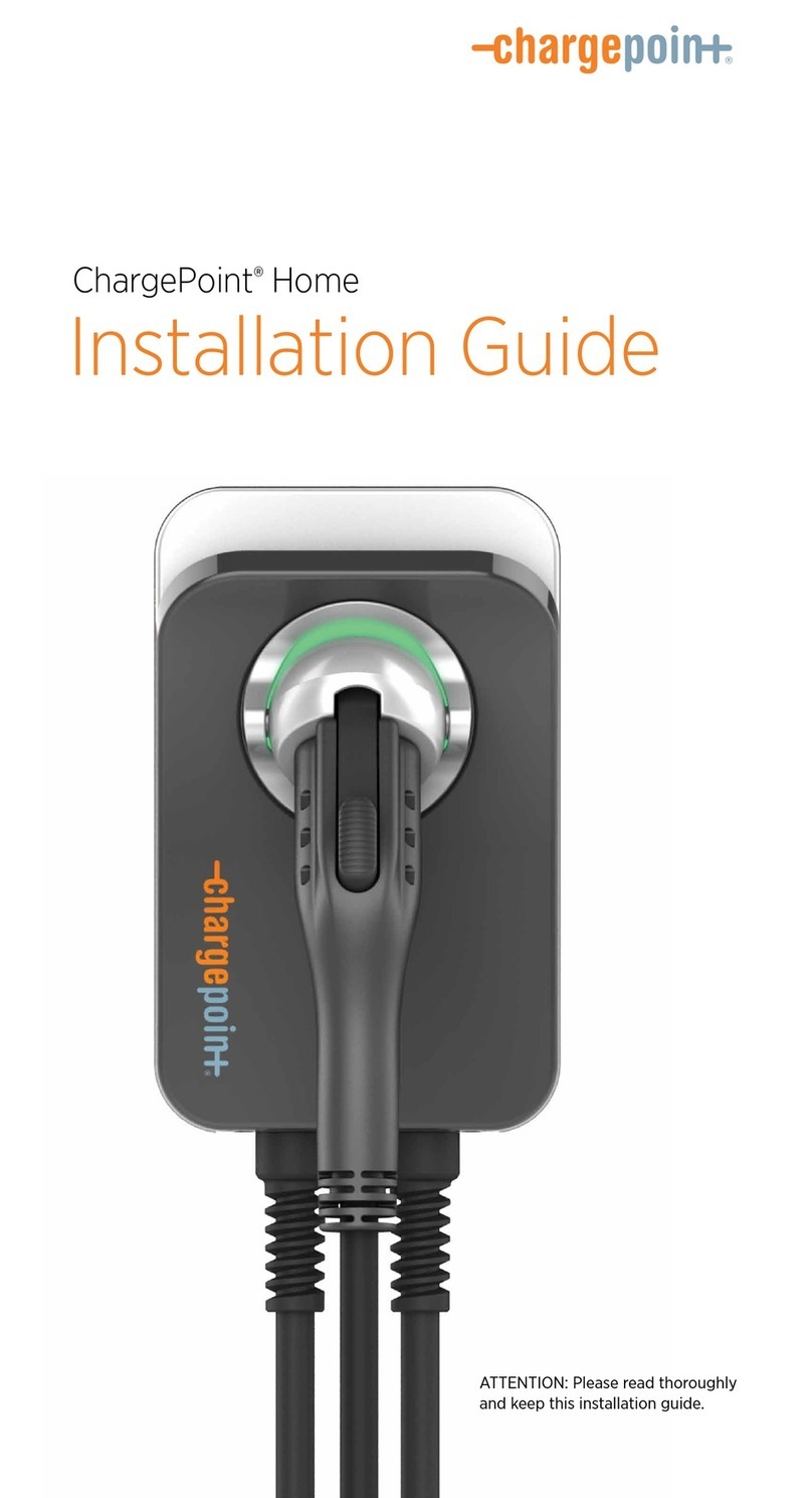
ChargePoint Home User manual

ChargePoint

ChargePoint Home User manual

ChargePoint CT2021 User manual

ChargePoint

ChargePoint CT2021 User manual

ChargePoint Home User manual

ChargePoint

ChargePoint Home User manual

ChargePoint Express 250 User manual

ChargePoint

ChargePoint Express 250 User manual

ChargePoint Home FlexCharfePoint User manual

ChargePoint

ChargePoint Home FlexCharfePoint User manual

ChargePoint Home Flex J1772 User manual

ChargePoint

ChargePoint Home Flex J1772 User manual

ChargePoint CT4000 Family User manual

ChargePoint

ChargePoint CT4000 Family User manual

ChargePoint Express 200 User manual

ChargePoint

ChargePoint Express 200 User manual

ChargePoint CT4000-HD Guide

ChargePoint

ChargePoint CT4000-HD Guide

ChargePoint Express 250 User manual

ChargePoint

ChargePoint Express 250 User manual

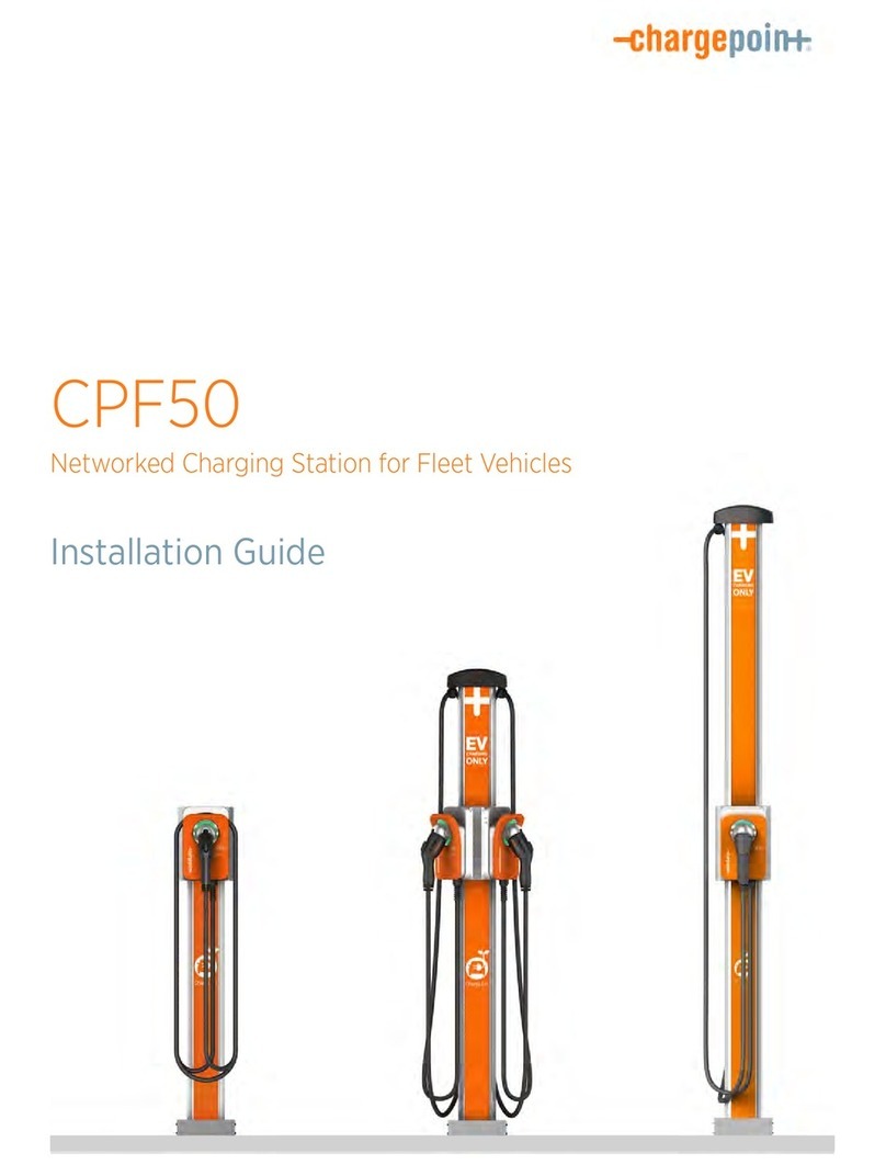
ChargePoint CPF50 User manual

ChargePoint

ChargePoint CPF50 User manual

ChargePoint CP6000 Series User manual

ChargePoint

ChargePoint CP6000 Series User manual

Popular Batteries Charger manuals by other brands

Gembird MP3A-UC-ACCAR user manual

Gembird

Gembird MP3A-UC-ACCAR user manual

Midtronics GR8 1100 instruction manual

Midtronics

Midtronics GR8 1100 instruction manual

Ferm BCM1020 Original instructions

Ferm

Ferm BCM1020 Original instructions

Delta-q RC Series user manual

Delta-q

Delta-q RC Series user manual

Mobitronic MBC-2000A/S user manual

Mobitronic

Mobitronic MBC-2000A/S user manual

ABB HT576005 Operation manual

ABB

ABB HT576005 Operation manual

Radio Shack 23-334 owner's manual

Radio Shack

Radio Shack 23-334 owner's manual

Huskie Tools CH-90 Product guide

Huskie Tools

Huskie Tools CH-90 Product guide

Panasonic FZ-VCBT11 operating instructions

Panasonic

Panasonic FZ-VCBT11 operating instructions

Fluke PM8907 instruction sheet

Fluke

Fluke PM8907 instruction sheet

Sunforce 50048 manual 

Sunforce

Sunforce 50048 manual 

Hama Delta Allround 00081350 operating instructions

Hama

Hama Delta Allround 00081350 operating instructions

Juicy Power AP4-0011A User reference guide

Juicy Power

Juicy Power AP4-0011A User reference guide

Eurotops C7393 manual

Eurotops

Eurotops C7393 manual

Ansmann Racing xMove 2.0 Ultimate instruction manual

Ansmann Racing

Ansmann Racing xMove 2.0 Ultimate instruction manual

protech BFS-180 user manual

protech

protech BFS-180 user manual

SV green Smart Charger SV102 Operation manual

SV green

SV green Smart Charger SV102 Operation manual

Vocollect Talkman T5 manual

Vocollect

Vocollect Talkman T5 manual

manuals.online logo
manuals.online logoBrands
  • About & Mission
  • Contact us
  • Privacy Policy
  • Terms and Conditions

Copyright 2025 Manuals.Online. All Rights Reserved.