manuals.online logo
Brands
  1. Home
  2. •
  3. Brands
  4. •
  5. Chargetek
  6. •
  7. Batteries Charger
  8. •
  9. Chargetek RTIC-1210 User manual

Chargetek RTIC-1210 User manual

CHARGETEK
409 Calle San Pablo, Unit 104 ~ Camarillo, CA93012 ~ PHONE: (866) 482-7930 FAX: (805) 482-7936
WWW.CHARGETEK.COM
LIMITED WARRANTY
For two years from date of purchase, Chargetek Inc. will
at its discretion repair or replace for the original consumer,
free of charge any part or parts found to be defective by
Chargetek in workmanship or material. All shipping
charges under this warranty must be paid by the consumer.
Proof of purchase is required.
There is no other expressed warranty. Implied warranties,
including those of merchantability and fitness for a
particular purpose are limited to two years from the date
ofpurchase.Thisistheexclusiveremedyandconsequential
damages are excluded where permitted by law.
CHARGER OPERATION
The RTIC 1210 is fully automatic once installed properly. The
indictor lights (LEDs) informs the user of the progress of the
charging cycle and confirms proper connections. The charger
monitors and charges the battery to full capacity.
ELECTRICAL CHARACTERISTICS
AC Input Voltage Range: 100-132VAC
AC Input Current: 6A rms Maximum
Max. Charging Current: 11A(Fast Mode)
Max. Charging Voltage (Absorption Mode): 29-29.7VDC
Max. Float Voltage (Float Mode): 26.4-27VDC
LED INDICATORS
Charging Mode LEDs indicate the state of charge of the battery.
The green Float light is the final charge state indicating the bat-
tery is fully charged. Only one Charging Mode LED should be
on at any one time.
Charging Current LEDs indicate the amount of charging cur-
rent being delivered by the charger to all three outputs.
AC Power On LED indicatesAC power is applied to the charger
Charging Status LED indicates the output is connected properly
to the battery and is being charged.When properly installed the
Charging Status LED should be on.
PROTECTION MODES:
Over Temperature: The RTIC1210 will reduce its charging cur-
rent as its case temperature increases to insure proper operation.
In the event of a charger over temperature the unit will turn off
until it cools off and then restart automatically. This over tem-
perature condition is indicated by the AC Power on and Float
LEDs flashing. If the unit is operated in a very high ambient
temperature, it is possible for the temperature to increase fur-
ther, as indicated by the AC Power on and 7-10 Amp Charging
Current LEDs flashing. In the rare event this condition occurs
the AC power and three Battery Banks should be disconnected
and reconnected once the charger has cooled off.
Over Voltage: The charger is equipped with an overvoltage pro-
tection circuit in the event of a regulation malfunction. The
charger will turn off if the overvoltage persists. The AC power
and Battery Bank should be disconnected for 2 minutes and re-
connected to the batteries. An over voltage condition is indi-
cated by the AC Power On and Fast LEDs flashing. If the over
voltage persists then the factory should be consulted.
The RTIC1210 is a sophisticated 24 volt, 10Abattery charger. It
can be used as either an on-board or portable unit
Charging is controlled by an embedded microcontroller that
contains software developed and proprietary to Chargetek.This
electronic "brain" insures that the battery will be fully and prop-
erly recharged regardless its condition.The RTIC1210 precisely
controls charging voltage and current to insure a complete re-
charge every time. The charger may be left connected indefi-
nitely to the battery, maintaining full charge at all times.
The RTIC1210 utilizes state of the art high frequency power
processing that converts the AC line power to 24 VDC effi-
ciently and safely. The charger is completely waterproof and
sealed with UL approved 94VO flame retardant epoxy. This
sealing also provides extreme vibration and shock resistance
since the encapsulated unit is effectively a "brick".
Good battery maintenance procedures dictate that battery fluid
levels be checked on a regular basis, especially in high ambient
temperatures.
RTIC-1210
OWNER’SMANUAL
INSTALLATION
LOCATION
Do not mount directly over or under a battery or onto a carpeted,
upholstered or varnished surface.
Install in an area where all charger electrical cords will avoid hot
surfaces such as exhaust pipes and moving parts such as fan wheels.
Operating ambient temperature is 15 to 130 degrees Fahrenheit.
Storage temperature is -20 to 160 degrees Fahrenheit.
Pick an area that will provide as much surrounding cooling
clearance as possible for maximum efficiency and shortest recharge
times.Maintain a 12inch clearancearound chargerandnever mount
in the vicinity of explosives, pressurized cans or other flammable
material.
MOUNTING
Wear safety goggles, gloves and a long sleeve shirt when drilling
mounting holes near a battery.
In most cases, #10 stainless steel mounting bolts with aircraft nuts
or nylocks or #10 screws provide for solid mounting.
ELECTRICAL
DC WIRE CONNECTIONS
Each output should be connected only to a standard lead-acid bat-
tery.
DC wire connections must be made before plugging in the AC
cord. The charger will not operate until DC connections are made.
Do not remove DC connections while the AC cord is plugged in.
When installing in the bilge and or battery compartment of boats,
open hatches and operate bilge blowers if any for ten minutes to
remove any fumes and hydrogen gas. Be certain the area is
ventilated for personal health and safety
Keep wire routing from the charger to the battery neat and secure
by anchoring with cable tie to a solid surface every few inches, not
to exceed 18” intervals.
As is true with any device connected to a battery, an in-line fuse
added to the positive lead to the battery is recommended to pro-
vide protection if the DC cord is somehow damaged.
For a single 24 volt battery, connect the charger lead set to the
battery as follows; the charger red lead is connected to the battery
positiveterminal and theblack chargerlead is connected to negative
terminal of the battery. When charging two 12 volt batteries
connectedin series connectthe red lead of thechargerto thepositive
terminal of battery #1. Connected the negative terminal of battery
#1 to the positive terminal of battery #2. Connect the black lead of
the charger to the negative terminal of battery #2.All connections
should be clean and tight. See installation diagrams.
When connecting two batteries in series it is imperative that the
amount of discharge be equal for both batteries or excessive battery
voltage during charge will be occur resulting in an overvoltaged
battery. This will cause dangerous battery out gassing and
destruction. For accurate charge balancing regardless of loading
use the TPRO320 model.
AC Wire Connections
Note:
The Chargetek RTIC 1210 is equipped with a factory installed 6’
grounded AC cord. Though hook up is only a matter of plugging
this cord into a suitable extension cord, please follow the following
precautionary tips.
Insure that the AC cord cannot reach moving parts, lids, hoods,
etc. Secure with a cable tie to solid anchor point if necessary.
The charger will operate properly with either 115 volts 50 Hz or
115 volts 60 Hz AC input. Never use 220 volt service with this
unit.
CAUTION:
Never connect the AC plug into an electrical outlet when you are
wet or barefoot.
Single 24V Battery
Connection
SAFETY INSTRUCTIONS
CAUTION: The following are important safety instructions. Save
these instructions.
Charge only lead acid, (maintenance free or refillable), or “gel-cell”
rechargeable batteries. Other types of batteries may burst causing personal
injury and damage
Never smoke or allow sparks or flame in the vicinity of a battery.
Someone should be within range of your voice and close enough to come
to your aid when you are working near a battery.
Wear eye protection and clothing protection. Avoid touching eyes while
working near a battery.
Have plenty of fresh water and soap nearby in case battery acid contact’s
skin, clothing or eyes.
If battery acid contact’s skin or clothing, wash immediately with soap
and water. If acid enters eyes, immediately flood eyes with running cold
water for at least ten minutes and get immediate medical attention.
Never operate a charger with a damaged cord or plug. Wearing ofAC and
DC cords, accidentally nicking or cutting the cords could result in sparking
and cause injury.
Never operate a charger that has been damaged in any way or try to
disassemble. Return to factory when service or replacement is required.
Incorrect reassembly may result in a risk of electrical shock or fire.
Become familiar with all instructions, specifications and cautionary
markings on chargers, batteries and equipment used. Only adults should
install and operate the charger. Children should be kept out of reach of the
charger and batteries it is charging.
When using an extension cord the Chargetek RTIC 1210 requires a quality
grounded extension cord of at least 16 awg wire size for cords up to 50’
and a minimum of 14 awg for cords up to 150’.
Never unplug a cord by pulling on the cord itself. Always grasp the plug
when disconnecting the charger.
Even though the Chargetek RTIC1210 is waterproof and designed for
harsh environments, do not operate submerged.
Never charge a frozen battery. If the battery has an odor or is visibly
damaged disconnect charger and consult factory.
Study battery manufacturer’s precautions such as removing or not
removing cell caps while charging.
Keep batteries full. Add distilled water in each cell until it reaches levels
specified by battery
Keep battery terminals clean.Always unplug charger before cleaning and
be careful to keep corrosion from coming in contact with eyes.
Remove personal metal items such as rings, bracelets, necklaces, and
watches when working with a lead-acid battery. A lead-acid battery can
produce a short circuit high enough to weld a ring, etc. to metal, causing a
severe burn.
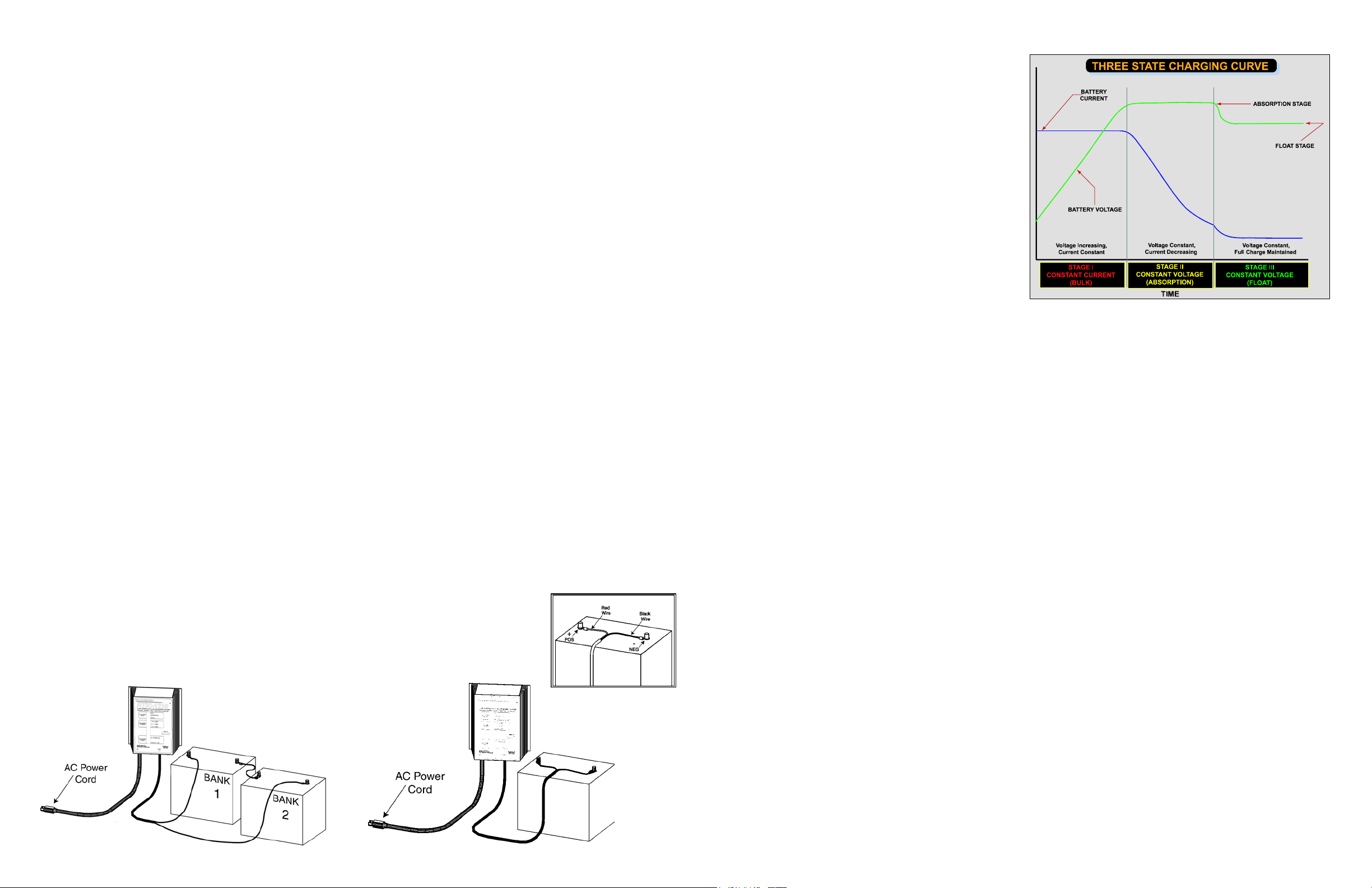
THREE STATE CHARGE CYCLE
The RTIC1210 employs a three state charge routine. This is the
charging procedure most lead-acid battery manufacturers rec-
ommend to return full capacity efficiently and extend battery
life. Please refer to the figure Three State Charging Curve dia-
gram.
STAGE I: CONSTANT CURRENT CHARGING OR BULK CHARGE MODE
Assuming the battery is starting in a discharged state, the charg-
ing is operating in constant current mode, where the charger
current is maintained at a constant value and the battery voltage
is allowed to rise as it is being recharged. Approximately 80%
of battery capacity is returned in the constant current region.
STAGE II: ABSORPTION MODE
When the battery voltage reaches approximately 2.4 volts per
cell, or 28.8 volts for a 24V battery, the charger voltage is held
constant at this level and the battery current is allowed to re-
duce. This voltage is maintained until the charging current re-
duces substantially indicating a full charge. At this point the
battery is fully charged.
STAGE III: FLOAT MODE
Float mode is the final stage of the charging routine. Float mode
is where the voltage on the battery is maintained at approxi-
mately 2.25 volts per cell, or 27 volts for a 24V battery. This
voltage will maintain the full charge condition in the battery
withoutboilingout electrolyte or overchargingthe battery.When
the charger is in this mode all lights on the RTIC1210 should be
green.
Two 12V Battery
Connection

Other Chargetek Batteries Charger manuals

Chargetek RTIC-1120-WP User manual

Chargetek

Chargetek RTIC-1120-WP User manual

Chargetek RTIC-1210-FC User manual

Chargetek

Chargetek RTIC-1210-FC User manual

Chargetek CT500-5 User manual

Chargetek

Chargetek CT500-5 User manual

Chargetek RTIC-2210-WP User manual

Chargetek

Chargetek RTIC-2210-WP User manual

Chargetek RTIC-2307 User manual

Chargetek

Chargetek RTIC-2307 User manual

Chargetek RTIC 2405-WP User manual

Chargetek

Chargetek RTIC 2405-WP User manual

Chargetek RTIC-1405-FC User manual

Chargetek

Chargetek RTIC-1405-FC User manual

Chargetek RTIC-2307-FC User manual

Chargetek

Chargetek RTIC-2307-FC User manual

Chargetek RTIC-1120-FC User manual

Chargetek

Chargetek RTIC-1120-FC User manual

Chargetek CT500-3 User manual

Chargetek

Chargetek CT500-3 User manual

Chargetek RTIC-1307-WP User manual

Chargetek

Chargetek RTIC-1307-WP User manual

Chargetek RTIC-2120-FC User manual

Chargetek

Chargetek RTIC-2120-FC User manual

Chargetek CK150-4 User manual

Chargetek

Chargetek CK150-4 User manual

Chargetek CT500 - 1 User manual

Chargetek

Chargetek CT500 - 1 User manual

Chargetek RTIC-1120-W User manual

Chargetek

Chargetek RTIC-1120-W User manual

Chargetek RTIC-2210-FC User manual

Chargetek

Chargetek RTIC-2210-FC User manual

Chargetek TPRO-220 User manual

Chargetek

Chargetek TPRO-220 User manual

Chargetek RTIC-2120-WP User manual

Chargetek

Chargetek RTIC-2120-WP User manual

Chargetek CT500-6 User manual

Chargetek

Chargetek CT500-6 User manual

Chargetek TPRO-320 User manual

Chargetek

Chargetek TPRO-320 User manual

Chargetek RTIC-1307-FC User manual

Chargetek

Chargetek RTIC-1307-FC User manual

Chargetek CK150-2 User manual

Chargetek

Chargetek CK150-2 User manual

Chargetek RTIC-1405-WP User manual

Chargetek

Chargetek RTIC-1405-WP User manual

Chargetek RTIC-2405-FC User manual

Chargetek

Chargetek RTIC-2405-FC User manual

Popular Batteries Charger manuals by other brands

MINN KOTA 1821065 owner's manual

MINN KOTA

MINN KOTA 1821065 owner's manual

efacec EFAPOWER EV-QC24S Installation and user manual

efacec

efacec EFAPOWER EV-QC24S Installation and user manual

Duracell DRCHDIG user manual

Duracell

Duracell DRCHDIG user manual

OE electrics OE Elsafe ARC-H quick start guide

OE electrics

OE electrics OE Elsafe ARC-H quick start guide

Hulk HU6525 user manual

Hulk

Hulk HU6525 user manual

Flotec FPDC30 owner's manual

Flotec

Flotec FPDC30 owner's manual

Williams Sound BAT KT7 Quick setup guide

Williams Sound

Williams Sound BAT KT7 Quick setup guide

Hyundai HYSC-7000 user manual

Hyundai

Hyundai HYSC-7000 user manual

ECOSOL POWERSTICK quick start guide

ECOSOL

ECOSOL POWERSTICK quick start guide

Circutor Wallbox eNext Series installation guide

Circutor

Circutor Wallbox eNext Series installation guide

ULTIMATE SPEED 346098 2004 instructions

ULTIMATE SPEED

ULTIMATE SPEED 346098 2004 instructions

GreenWorks Pro Ultapower 60V CAC801 Operator's manual

GreenWorks Pro

GreenWorks Pro Ultapower 60V CAC801 Operator's manual

Sentry Voyager Series Installation & operation

Sentry

Sentry Voyager Series Installation & operation

MyCharge RAPID RECHARGE quick start guide

MyCharge

MyCharge RAPID RECHARGE quick start guide

Circontrol Raption 150 Series installation manual

Circontrol

Circontrol Raption 150 Series installation manual

Sibata QCA-W5 Operation manual

Sibata

Sibata QCA-W5 Operation manual

Wallbox Commander 2 user guide

Wallbox

Wallbox Commander 2 user guide

bp pulse user guide

bp

bp pulse user guide

manuals.online logo
manuals.online logoBrands
  • About & Mission
  • Contact us
  • Privacy Policy
  • Terms and Conditions

Copyright 2025 Manuals.Online. All Rights Reserved.