DH Instruments E-DWT-H User manual

© 2009 DH Instruments, a Fluke Company
E-DWT-H
Electronic Deadweight Tester
Operation and Maintenance Manual

E-DWT-H OPERATION AND MAINTENANCE MANUAL
© 2009 DH Instruments, a Fluke Company
WWarning
•High pressure liquids and gases are potentially hazardous. Energy stored
in these liquids and gases can be released unexpectedly and with extreme
force. High pressure systems should be assembled and operated only by
personnel who have been instructed in proper safety practices.
•This instrument is not to be operated in any other manner than that
specified by the manufacturer.
© 2009 DH Instruments, a Fluke Company All rights reserved.
Information in this document is subject to change without notice. No part of this document may be reproduced or transmitted in any
form or by any means, electronic or mechanical, for any purpose, without the express written permission of DH Instruments, a
Fluke Company 4765 East Beautiful Lane, Phoenix AZ 85044-5318, USA.
DH Instruments makes sincere efforts to ensure accuracy and quality of its’ published materials; however, no warranty, expressed
or implied, is provided. DH Instruments disclaims any responsibility or liability for any direct or indirect damages resulting from the
use of the information in this manual or products described in it. Mention of any product or brand does not constitute an
endorsement by DH Instruments of that product or brand. This manual was originally composed in English and was subsequently
translated into other languages. The fidelity of the translation cannot be guaranteed. In case of conflict between the English version
and other language versions, the English version predominates.
Products described in this manual are manufactured under international patents and one or more of the following U.S. patents:
5,142,483; 5,257,640; 5,331,838; 5,445,035. Other U.S. and international patents pending.
AutoRange, AutoZ, DH Instruments,DH,DHI, CalTool, COMPASS, E-DWT, RPM4-E-DWT, QDUT, Q-RPT and SDS are
trademarks, registered and otherwise, of DH Instruments, a Fluke Company.
Document No. 3389682
090318
Printed in the USA

TABLE OF CONTENTS
Page I © 2009 DH Instruments, a Fluke Company
Table Of Contents
Table Of Contents ....................................................................I
Tables ....................................................................................V
Figures..................................................................................VI
About This Manual ................................................................VII
1. Introduction ...................................................................... 1
1.1 Product Overview...................................................................................................................................1
1.2 Specifications .........................................................................................................................................2
1.2.1 General Specifications.................................................................................................................................2
1.2.2 Battery and Charger Pack ...........................................................................................................................3
1.2.3 Pressure Measurement Specifications ......................................................................................................3
1.2.3.1 Reference Pressure Transducers (RPT)....................................................................................................3
1.2.3.2 On-Board Barometer ..................................................................................................................................4
1.3 Views and Schematics ...........................................................................................................................5
1.3.1 E-DWT Views.................................................................................................................................................5
1.3.1.1 Front View, Single Q-RPT E-DWT .............................................................................................................5
1.3.1.2 Front View, Dual Q-RPT E-DWT................................................................................................................6
1.3.1.3 Rear View...................................................................................................................................................7
1.3.2 RPM4-E-DWT Reference Pressure Monitor Views ....................................................................................7
1.3.2.1 Front Panel.................................................................................................................................................7
1.3.2.2 Rear Panel .................................................................................................................................................8
1.3.3 Battery/Charger Pack Views........................................................................................................................8
1.3.4 E-DWT-H Dimensions...................................................................................................................................9
1.3.5 E-DWT-H Hydraulic Schematic ...................................................................................................................9
1.3.5.1 Single Q-RPT E-DWT-H Schematic...........................................................................................................9
1.3.5.2 Dual Q-RPT E-DWT-H Schematic ...........................................................................................................10
2. Installation ..................................................................... 11
2.1 Unpacking and Inspection...................................................................................................................11
2.1.1 Removing from Packaging ........................................................................................................................11
2.1.2 Inspecting Contents ...................................................................................................................................11
2.2 Site Requirements................................................................................................................................11
2.3 Setup .....................................................................................................................................................12
2.3.1 Preparing for Operation.............................................................................................................................12
2.3.2 Filling E-DWT-H with Calibration Fluid and Purging Air..............................................................................12
2.3.3 Setting Up AutoTest Files..........................................................................................................................13
2.4 Operational Check................................................................................................................................13
2.4.1 RPM4-E-DWT Pressure Measurement......................................................................................................13
2.4.1.1 Single Q-RPT Pressure Measurement.....................................................................................................13
2.4.1.2 Dual Q-RPT Pressure Measurement .......................................................................................................13
2.4.2 E-DWT Pressure Generation and Control ................................................................................................14
2.5 Short Term Storage..............................................................................................................................15
2.6 Long Term Storage, Preparation for Shipping...................................................................................16
3. Operation........................................................................ 17
3.1 General Operating Principles ..............................................................................................................17
3.1.1 Multiple Ranges (HI and LO Q-RPT, AutoRange) ....................................................................................17
3.1.2 Pressure Ready/Not Ready .......................................................................................................................18
3.1.3 Automated Test And Calibration Sequences ..........................................................................................18
3.1.4 Typical Operating Sequence To Run A Test............................................................................................18

E-DWT-H OPERATION AND MAINTENANCE MANUAL
© 2009 DH Instruments, a Fluke Company Page II
3.2 Test Port Connection ...........................................................................................................................19
3.2.1 RPM4-E-DWT ATM Port(s) .........................................................................................................................20
3.3 Battery/Charger Pack (Optional Accessory) ......................................................................................20
3.4 Selecting the Hi or Lo Q-RPT (Dual Q-RPT Models Only) .....................................................................21
3.5 Pressure Generation And Adjustment................................................................................................24
3.5.1 Filling And Priming, Reservoir Pump.......................................................................................................25
3.5.2 Pressure Generation And Rough Adjustment, Variable Volume...........................................................26
3.5.3 Pressure Fine Adjustment, Fine Adjust Valve.........................................................................................27
3.6 RPM4-E-DWT User Interface................................................................................................................27
3.6.1 MAIN RUN Screen ......................................................................................................................................27
3.6.2 Function / Data Keypad Layout and Protocol..........................................................................................29
3.6.3 Optional Remote [ENT] (ENTER) Footswitch ..........................................................................................29
3.6.4 Sounds ........................................................................................................................................................30
3.7 RPM4-E-DWT Direct Function Keys....................................................................................................30
3.7.1 Summary .....................................................................................................................................................30
3.7.2 [RANGE] ......................................................................................................................................................31
3.7.3 [UNIT]...........................................................................................................................................................32
3.7.4 [MODE] ........................................................................................................................................................33
3.7.5 [AUTORANGE] ............................................................................................................................................33
3.7.6 [LEAK CK] ...................................................................................................................................................35
3.7.7 [DIsplay] ......................................................................................................................................................36
3.7.7.1 Avg (Average) ..........................................................................................................................................37
3.7.7.2 Rate..........................................................................................................................................................38
3.7.7.3 DEV (Deviation)........................................................................................................................................39
3.7.7.4 RPT ..........................................................................................................................................................40
3.7.7.5 HI/LO ........................................................................................................................................................41
3.7.7.6 Freeze ......................................................................................................................................................41
3.7.7.7 Clean ........................................................................................................................................................42
3.7.8 [HEAD] .........................................................................................................................................................42
3.7.9 [SDS]............................................................................................................................................................44
3.7.10 [AUTOZ].......................................................................................................................................................44
3.7.11 [ENT/AutoTest] (Run AutoTest) ................................................................................................................45
3.7.11.1 AutoTest Initialization ...............................................................................................................................46
3.7.11.2 Test Execution..........................................................................................................................................47
3.8 [SETUP] .................................................................................................................................................49
3.8.1 <1RANGE> ..................................................................................................................................................49
3.8.1.1 Saving An AutoRange Range ..................................................................................................................49
3.8.1.2 Deleting AutoRange Ranges....................................................................................................................50
3.8.2 <2RES> (Resolution) ..................................................................................................................................50
3.8.3 <3stab> (Stability) ......................................................................................................................................51
3.8.4 <4UL> (Upper Limit) ...................................................................................................................................52
3.8.4.1 Over Pressure Function ...........................................................................................................................53
3.8.5 <5ATEST>....................................................................................................................................................53
3.8.5.1 DATA........................................................................................................................................................53
3.8.5.2 FILE..........................................................................................................................................................55
3.9 [SPECIAL] .............................................................................................................................................56
3.9.1 <1AUTOZ> ...................................................................................................................................................57
3.9.2 <2REMOTE> ................................................................................................................................................59
3.9.2.1 <1COM1, 2COM2> ..................................................................................................................................59
3.9.2.2 <3IEEE-488>............................................................................................................................................60
3.9.2.3 <4FORMAT> ............................................................................................................................................60
3.9.2.4 <5RS232 SELF-TEST>............................................................................................................................60
3.9.3 <3HEAD> .....................................................................................................................................................61
3.9.4 <4SDS>........................................................................................................................................................61
3.9.5 <5prefs>.......................................................................................................................................................61
3.9.5.1 <1SCRSVR> ............................................................................................................................................61
3.9.5.2 <2SOUND> ..............................................................................................................................................62
3.9.5.3 <3time> ....................................................................................................................................................62
3.9.5.4 <4id> ........................................................................................................................................................63
3.9.5.5 <5LEVEL> (Security)................................................................................................................................63
3.9.6 <6PUNIT>.....................................................................................................................................................66
3.9.7 <7INTERN> ..................................................................................................................................................67
3.9.7.1 <1BARO> .................................................................................................................................................67
3.9.7.2 <2READRT> ............................................................................................................................................68
3.9.7.3 <3RPT2X>................................................................................................................................................68
3.9.7.4 <4LO VNT> ..............................................................................................................................................69
3.9.7.5 <5log> ......................................................................................................................................................69
3.9.8 <8CAL> ........................................................................................................................................................69
3.9.9 <9RESET> ...................................................................................................................................................69
3.9.9.1 <1SETS>..................................................................................................................................................70
3.9.9.2 <2 Units> ..................................................................................................................................................70

TABLE OF CONTENTS
Page III © 2009 DH Instruments, a Fluke Company
3.9.9.3 <3ATEST>................................................................................................................................................71
3.9.9.4 <4 Cal>.....................................................................................................................................................71
3.9.9.5 <5 All> ......................................................................................................................................................71
4. Remote Operation............................................................ 73
4.1 Overview ...............................................................................................................................................73
4.2 Interfacing .............................................................................................................................................73
4.2.1 RS232 Interface...........................................................................................................................................73
4.2.1.1 COM1 .......................................................................................................................................................73
4.2.1.2 COM2 .......................................................................................................................................................74
4.3 Programming Formats.........................................................................................................................74
4.3.1 Program Message Format .........................................................................................................................74
4.3.2 Error Queue.................................................................................................................................................75
4.3.2.1 Using Query Type Commands.............................................................................................................75
4.4 Commands............................................................................................................................................76
4.4.1 Programming Messages ............................................................................................................................76
4.4.2 ERROR Messages ......................................................................................................................................77
4.4.3 Program Message Description Overview.................................................................................................78
4.4.4 Program Message Descriptions................................................................................................................79
5. Maintenance, Adjustments and Calibration ........................... 97
5.1 Overview ...............................................................................................................................................97
5.2 RPM4-E-DWT Maintenance..................................................................................................................97
5.2.1 AutoZero of Q-RPTS ..................................................................................................................................97
5.2.2 Adjustment of the On-Board Barometer ..................................................................................................98
5.3 RPM4-E-DWT Q-RPT Calibration.........................................................................................................98
5.3.1 Principle ......................................................................................................................................................98
5.3.1.1 PA and PM Coefficients ...........................................................................................................................99
5.3.2 Equipment Required ..................................................................................................................................99
5.3.3 Set-Up and Preparation ...........................................................................................................................100
5.3.4 Recommended Calibration Point Sequence ..........................................................................................100
5.3.5 RPT Calibration Using CalTool for Q-RPTSSoftware ...........................................................................101
5.3.6 Editing and Viewing Q-RPT Calibration Information ............................................................................101
5.3.7 Q-RPT Adjustment Without CalTool for Q-RPTSSoftware...................................................................102
5.4 E-DWT Maintenance...........................................................................................................................103
5.4.1 E-DWT Overhaul .......................................................................................................................................103
5.4.2 Reloading Embedded Software into RPM4-E-DWT Flash Memory......................................................104
5.4.3 Filling E-DWT-H with Calibration Fluid and Purging Air Using the Optional Fill Kit.................................104
5.4.4 RPM4-E-DWT Subassembly Description and Location ........................................................................105
5.4.4.1 Micro Board ............................................................................................................................................105
5.4.4.2 Driver Board ...........................................................................................................................................105
5.4.4.3 On-Board Barometer ..............................................................................................................................106
5.4.4.4 Q-RPT Module .......................................................................................................................................106
5.4.4.5 Display....................................................................................................................................................106
5.4.4.6 Cooling Fan ............................................................................................................................................106
5.4.5 Hydraulic Schematic of Q-RPT Module..................................................................................................106
6. Troubleshooting .............................................................107
7. Appendix .......................................................................111
7.1 Unit Conversion..................................................................................................................................111
7.1.1 Pressure ....................................................................................................................................................111
8. Warranty ........................................................................113
8.1 Overview .............................................................................................................................................113
9. Glossary ........................................................................115

E-DWT-H OPERATION AND MAINTENANCE MANUAL
© 2009 DH Instruments, a Fluke Company Page IV
Notes

TABLES & FIGURES
Page V © 2009 DH Instruments, a Fluke Company
Tables
Table 1. Reference Pressure Transducer (Q-RPT) Module Designations and Ranges.............................. 3
Table 2. E-DWT-H packing list................................................................................................................... 11
Table 3. Settings and what they are specific to (range, measurement mode, Q-RPT, system)................ 18
Table 4. Summary of RPM4-E-DWT function key operation ..................................................................... 31
Table 5. Settings made by AutoRange ...................................................................................................... 34
Table 6. Security levels .............................................................................................................................. 64
Table 7. UNIT function - available units of measure.................................................................................. 66
Table 8. READRT – display update rates .................................................................................................. 68
Table 9. Reset – Sets................................................................................................................................. 70
Table 10. Reset – Cal ................................................................................................................................ 71
Table 11. Reset – All.................................................................................................................................. 71
Table 12. COM1 pin designations and connections .................................................................................. 73
Table 13. COM2 DB-9F pin designations .................................................................................................. 74
Table 14. Program message list ................................................................................................................ 76
Table 15. Error #s and descriptions ........................................................................................................... 77
Table 16. Calibration point sequence for E-DWT-H RPM4-E-DWT Q-RPTs .......................................... 101
Table 17. Troubleshooting guide ............................................................................................................. 107
Table 18. Pressure unit of measure conversion coefficients ................................................................... 111
Table 19. DHI Authorized Service Providers ........................................................................................... 113

E-DWT-H OPERATION AND MAINTENANCE MANUAL
© 2009 DH Instruments, a Fluke Company Page VI
Figures
Figure 1. E-DWT-H with single Q-RPT, front view....................................................................................... 5
Figure 2. E-DWT-H with dual Q-RPT, front view ......................................................................................... 6
Figure 3. E-DWT-H rear view....................................................................................................................... 7
Figure 4. RPM4-E-DWT reference pressure monitor front view .................................................................. 7
Figure 5. RPM4-E-DWT reference pressure monitor rear view................................................................... 8
Figure 6. Battery/charger pack front and rear.............................................................................................. 8
Figure 7. E-DWT-H dimensions ................................................................................................................... 9
Figure 8. E-DWT-H with single Q-RPT hydraulic schematic ....................................................................... 9
Figure 9. E-DWT-H with dual Q-RPTs hydraulic schematic ...................................................................... 10
Figure 10. Battery pack/charger................................................................................................................. 21
Figure 11. E-DWT-H with dual Q-RPT, front view ..................................................................................... 23
Figure 12. E-DWT-H with dual Q-RPTs hydraulic schematic .................................................................... 24
Figure 13. MAIN RUN screen display fields............................................................................................... 28
Figure 14. Keypad layout ........................................................................................................................... 29
Figure 15. RPM4-E-DWT internal view.................................................................................................... 105
Figure 16. Hydraulic schematic RPM4-E-DWT Q-RPT Module ............................................................... 106

ABOUT THIS MANUAL
Page VII © 2009 DH Instruments, a Fluke Company
About This Manual
This manual is intended to provide the user with the basic information necessary to operate an E-DWT-H
electronic deadweight tester. It also includes a great deal of additional information provided to allow you
to optimize the use of the instrument and take full advantage of its many features and functions.
Before using the manual, take a moment to familiarize yourself with the Table of Contents structure: Sections
1.1, 2 and 3 provide orientation, start up and operation information. Section 4 is for remote communication
with the RPM4-E-DWT from an external computer. Section 5 provides maintenance and calibration
information. Section 6 is a quick troubleshooting guide. Use it to troubleshoot unexpected E-DWT-H behavior
based on the symptom of that behavior.
Note
For those of you who “don’t read manuals”, go directly to Section 2.3 to set up
your E-DWT-H and then go to Section 3.1.4 for a typical test procedure. This will
get you up and running quickly with a minimal risk of causing damage to yourself
or your new instrument. THEN… when you have questions or start to wonder
about all the great features you might be missing, get into the manual!
Manual Conventions
WCaution
“Caution” is used in throughout the manual to identify conditions or actions that
could cause harm to the E-DWT-H or to the devices that are connected to the
E-DWT-H.
WWarning
“Warning” is used in throughout the manual to identify actions that could pose a
hazard to the user of the E-DWT-H.
Note
“Note” is used throughout the manual to identify operating and applications advice
and additional explanations.
[ ] indicates direct function keys (e.g., [RANGE]).
< > indicates RPM4-E-DWT screen displays (e.g., <1yes>).

E-DWT-H OPERATION AND MAINTENANCE MANUAL
© 2009 DH Instruments, a Fluke Company Page VIII
Notes

1. INTRODUCTION
Page 1 © 2009 DH Instruments, a Fluke Company
1. Introduction
1.1 Product Overview
The E-DWT-H electronic deadweight tester is to generate, set and measure pressure as required for a
variety of pressure calibration and testing applications. The E-DWT-H is used in the lab or instrument
shop or can be taken into the field for performing in-situ calibrations and tests. This hydraulic pressure
calibration system combines a high performance electronic reference pressure monitor and manually
operated pressure generation and control hardware in a single, compact and rugged package. E-DWT-H
offers the ease of use and precision of continuous, real time electronic pressure measurement with the
simple and direct pressure control of high quality manual pressure hardware. E-DWT is named
“electronic deadweight tester” because it is intended as a lightweight and easy to use, modern alternative
to conventional piston-cylinder and weight based deadweight testers.
The E-DWT’s electronic reference pressure monitor is a special version of DHI’s RPM4, designated
RPM4-E-DWT. RPM4-E-DWT can be configured with one or two high precision quartz reference pressure
transducers (Q-RPTs) with ranges from 7 MPa (1 000 psi) to 200 MPa (30 000 psi).
The RPM4-E-DWT is controlled locally by the operator using its front panel display, keypad and optional
foot pedal or remotely by a computer using ASCII character command strings over its RS-232 interface.
RPM4-E-DWT uses an AutoRange feature to automatically select the most appropriate Q-RPT and to
optimize the E-DWT-H setup to cover the desired range of operation. When two Q-RPTs are included, a
half-turn valve isolates and protects the Lo Q-RPT from high pressure when the Hi Q-RPT is in use.
Visual and audible indicators assist the operator in setting the shut off valve correctly.
The E-DWT-H includes the hardware necessary to fill and prime the system under test and generate and
precisely adjust pressure up to E-DWT’s 200 MPa (30 000 psi).
The E-DWT-H can be powered with an optional battery/charger pack for use in locations where AC power
is not readily available.

E-DWT-H OPERATION AND MAINTENANCE MANUAL
© 2009 DH Instruments, a Fluke Company Page 2
1.2 Specifications
1.2.1 General Specifications
Power requirements:
To RPM4-E-DWT:
To 12 VDC AC to DC power
supply :
12 VDC, 1.2 A
100 to 240VAC, 50-60 Hz
Temperature
Operating:
Storage:
10 to 40 °C
- 20 to 70 °C
Relative humidity
Operating:
Storage (in case):
0 to 70%
0 to 100%
Weight: 1 Q-RPT: 12 kg (26 lb) approx.
2 Q-RPT: 14 kg (30 lb) approx.
Dimensions
E-DWT footprint:
E-DWT height:
41.4 cm W x 37.1 cm D (16.3 in. x 14.6 in.)
26.9 cm (10.6 in.), 33.6 cm (13.2 in.) to max variable volume handle stroke
Pressure range: Dependent on Q-RPT(s) included in RPM4-E-DWT.
200 MPa (30 000 psi) maximum with standard variable volume
100 MPa (15 000 psi) maximum with high volume (-HV) variable volume
Operating medium: Delivered filled with oil (di-ethyl-hexyl sebacate) or dry.
Standard E-DWT-H compatible with Sebacate, silicon oils, propylene glycol,
fully fluorinated liquids, partially fluorinated liquids, isopropyl alcohol, distilled
water.
Reservoir capacity: 300 cc (18 in.3)
Variable volume displacement: Standard vv: 3 cc (0.18 in.3) (200 MPa (30 000 psi) maximum)
High volume vv: 7 cc (43 in.3) (100 MPa (15 000 psi) maximum)
Filling and priming pump
displacement:
3.7 cc (0.23 in.3)
TEST pressure connection: DH500 female.
Note: DH500 is a gland and collar type fitting for 6mm (1/4 in.) coned and
left hand threaded tubes equivalent to AE F250C, HIP HF4, etc.
Pressure Limits: Maximum Working Pressure: Range of RPM4-E-DWT monitor’s Hi Q-RPT.
200 MPa (30 000 psi) with standard variable volume, 100 MPa (15 000 psi)
with high volume variable volume.
Maximum priming pump pressure: 700 kPa (100 psi)
Maximum Working Pressure with Lo Q-RPT connected to TEST port:
Range of RPM4-E-DWT monitor’s Lo Q-RPT.
Lo Q-RPT pressure relief valve setting:
A40M Q-RPT: 44.7 MPa (6480 psi)
A20M Q-RPT: 22.3 MPa (3240 psi)
A14M Q-RPT: 15.7 MPa (2200 psi)
A10M Q-RPT: 10.8 MPa (1570 psi)
A7M Q-RPT: 7.6 MPa (1100 psi)
Communication ports: RS232 (COM1, COM2)

1. INTRODUCTION
Page 3 © 2009 DH Instruments, a Fluke Company
1.2.2 Battery and Charger Pack
The RPM4-E-DWT battery and charger pack is an optional accessory.
Power Requirements 100 to 240 VAC, 50/60 Hz, 15 W max consumption
Operating Temperature Range 10 to 40 °C
Storage Temperature Range - 20 to 70 °C
Weight 2 kg (4.4 lb)
Dimensions 8 cm H x 22.5 cm W x 20 cm D (3.1 in. x 8.9 in. x 7.9 in.)
Battery Type Nickel metal-hydride
Battery Voltage 12 VDC
Battery Capacity Typical: 9000 mAh
Min: 8200 mAh
Charge Time Full charge from empty, 14 to 16 hours approx.
Approx. Run Time, Full Charge 8 hours
1.2.3 Pressure Measurement Specifications
1.2.3.1 Reference Pressure Transducers (RPT)
The E-DWT’s RPM4-E-DWT is configured with one (Hi) or two (Hi and Lo) quartz
reference pressure transducer (Q-RPT) modules to measure pressure (see Table 1).
The Lo Q-RPT cannot be greater than A40M.
The Q-RPTs are intrinsically absolute, operating against a sealed vacuum
reference. Gauge pressure is defined by offsetting atmospheric pressure and
applying dynamic compensation for atmospheric changes using the on-board
barometer (see Section 3.9.1).
The complete E-DWT-H model definition includes the Q-RPTs included in its
RPM4-E-DWT. For example, an E-DWT-H with A200M and A20M Q-RPTs is
designated E-DWT-H A200M/A20M. An E-DWT-H with a single A200M Q-RPT
is designated E-DWT-H A200M.
Table 1. Reference Pressure Transducer (Q-RPT) Module Designations and Ranges
SI
VERSION US VERSION
Q-RPT
DESIGNATION MAXIMUM
RANGE
[kPa]
Gauge
MAXIMUM
RANGE
[psi]
Gauge
A200M1200 000 30 000
A140M1140 000 20 000
A100M1100 000 15 000
A70M170 000 10 000
A40M140 000 6 000
A20M120 000 3 000
A14M114 000 2 000
A10M110 000 1 500
A7M17 000 1 000

E-DWT-H OPERATION AND MAINTENANCE MANUAL
© 2009 DH Instruments, a Fluke Company Page 4
Warm Up Time 15 minute temperature stabilization recommended from
cold power up.
Normal Operating Temperature Range 10 to 40 °C
Resolution Default: 0.01 % of active range.
User adjustable to 1 ppm of Q-RPT maximum or 10 ppm
of active AutoRange, whichever is larger.
Precision1± 0.018% of reading or 0.0018% of Q-RPT span,
whichever is greater
Predicted Stability2One year: ± 0.0075% of reading or 0.0008% of Q-RPT
span, whichever is greater
Two year: +/- 0.015% of reading or 0.0015% of Q-RPT
span, whichever is greater
Measurement Uncertainty3One year: ± 0.02% of reading or 0.002% of Q-RPT span,
whichever is greater
Two year: ± 0.025% of reading or 0.0025% of Q-RPT
span, whichever is greater
1. Combined linearity, hysteresis, and repeatability.
2. Predicted Q-RPT measurement stability limit (k=2) assuming regular use of AutoZero function and
short term stability between rezeroing. As stability can only be predicted and varies from Q-RPT to
Q-RPT, stability for a specific Q-RPT should be established from experience.
3. Maximum deviation of the Q-RPT indication from the true value of applied pressure including
precision, predicted stability with rezeroing, temperature effect from 10 to 40 ºC and calibration
uncertainty (assumes calibration reference uncertainty of ±0.005% of reading, k=2), combined and
expanded (k=2) following the ISO “Guide to the Expression of Uncertainty in Measurement.”
1.2.3.2 On-Board Barometer
The measurement uncertainty of the on-board barometer is not significant to
E-DWT-H measurement uncertainty. The barometer is used only to measure
small, short term changes in atmospheric pressure to provide dynamic
compensation of the Q-RPT’s atmospheric pressure offset in gauge pressure
measurement mode (see Section 3.9.1)
Sensor Technology: Micro-machined silicon
Warm Up Time: None required
Resolution: 0.1 Pa (0.000015 psi)

1. INTRODUCTION
Page 5 © 2009 DH Instruments, a Fluke Company
1.3 Views and Schematics
1.3.1 E-DWT Views
1.3.1.1 Front View, Single Q-RPT E-DWT
ATEST1 port (DH500F)
BReservoir cap
CPriming pump
DReservoir cap vent valve
EReference pressure monitor (RPM4-E-DWT)
FTest shut off valve and fine pressure
adjustment
GReservoir shut off valve
HVariable volume (screw press)
IVariable volume piston position indicator
Figure 1. E-DWT-H with single Q-RPT, front view

E-DWT-H OPERATION AND MAINTENANCE MANUAL
© 2009 DH Instruments, a Fluke Company Page 6
1.3.1.2 Front View, Dual Q-RPT E-DWT
ATEST1 port (DH500F)
BReservoir cap
CPriming pump
DReservoir cap vent valve
EReference pressure monitor (RPM4-E-DWT)
FTest shut off valve and fine pressure adjustment
G‘Lo Q-RPT shut off’ valve position prompt LED
HLo Q-RPT shut off valve
I‘Lo Q-RPT active’ valve position prompt LED
J‘Lo Q-RPT active’ caution indicator
KReservoir shut off valve
LVariable volume (screw press)
MVariable volume piston position indicator
Figure 2. E-DWT-H with dual Q-RPT, front view

1. INTRODUCTION
Page 7 © 2009 DH Instruments, a Fluke Company
1.3.1.3 Rear View
AReservoir cap vent valve
BPriming pump
CReservoir cap
DTEST1 connection (DH500 F)
EPower connection (12 VDC)
FFootswitch (remote [ENT]) connection
(footswitch not included)
GTEST2 connection (DH500 F)
Figure 3. E-DWT-H rear view
1.3.2 RPM4-E-DWT Reference Pressure Monitor Views
1.3.2.1 Front Panel
APressure ready/not ready indicator
B2 x 20 vacuum fluorescent display
CRemote activity indicator
DCursor control key
EMulti-function keypad
Figure 4. RPM4-E-DWT reference pressure monitor front view

E-DWT-H OPERATION AND MAINTENANCE MANUAL
© 2009 DH Instruments, a Fluke Company Page 8
1.3.2.2 Rear Panel
A12VDC power supply connection
BAccessories connector (to E-DWT-H
rear panel FOOTSWITCH and LEDs)
CCOM2 connector
DCOM1 connector
EFan
FTEST(+) pressure port, Lo Q-RPT
Low Q-RPT is optional
GTEST(+) pressure port, Hi Q-RPT
HATM pressure port, Lo Q-RPT
IATM pressure port, Hi Q-RPT
JProduct label (bottom of case)
Figure 5. RPM4-E-DWT reference pressure monitor rear view
1.3.3 Battery/Charger Pack Views
ACooling fan
B12VDC output connector (to E-DWT)
CIEC power connection
DON/OFF switch (ON – battery connected to charger;
OFF - battery connected to 12 VDC output/E-DWT)
ECharge level indicator
FCharge level check switch
GBattery charging indicator (green –
charging; green flashing – fully charged.
Figure 6. Battery/charger pack front and rear
1. INTRODUCTION
Page 9 © 2009 DH Instruments, a Fluke Company
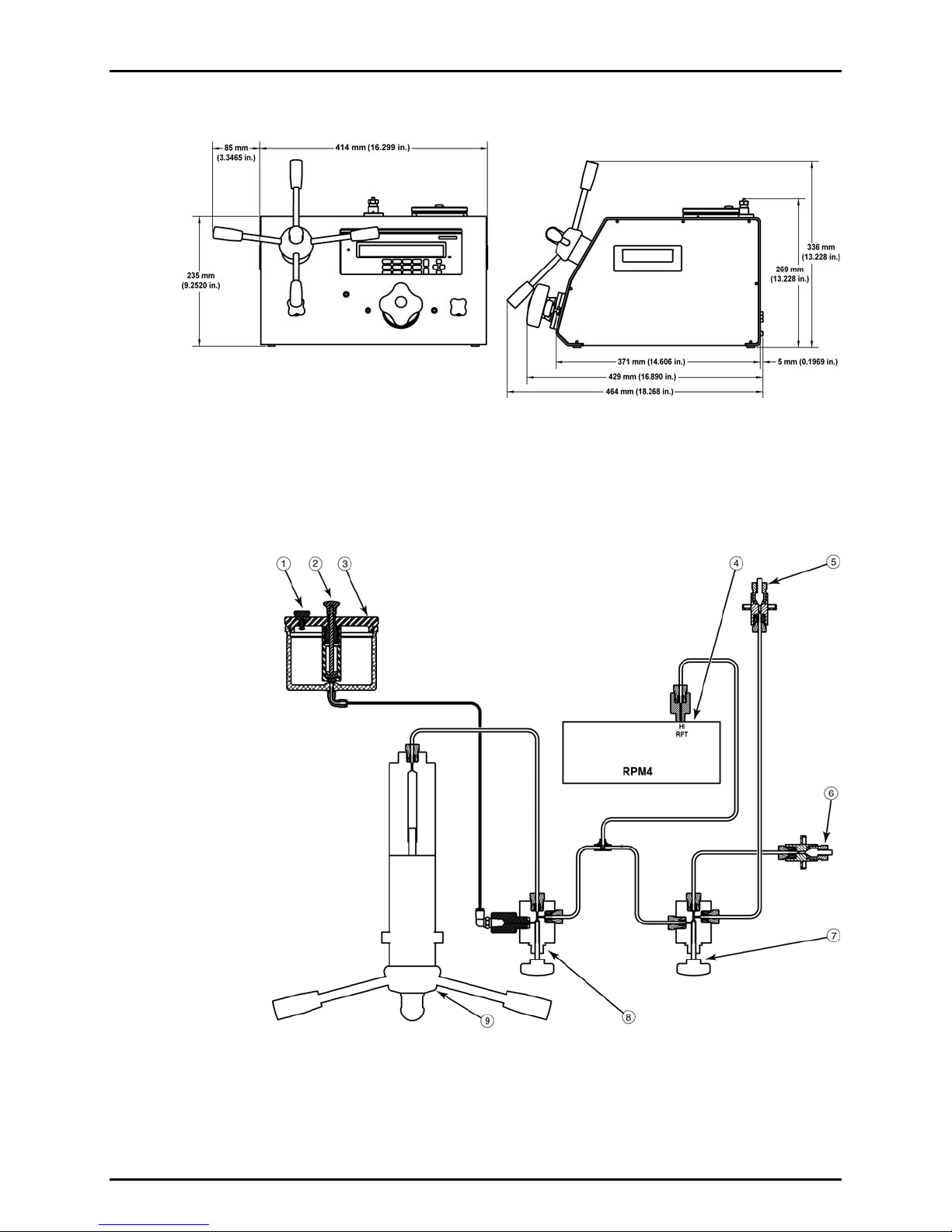
1.3.4 E-DWT-H Dimensions
Figure 7. E-DWT-H dimensions
1.3.5 E-DWT-H Hydraulic Schematic
1.3.5.1 Single Q-RPT E-DWT-H Schematic
AReservoir vent valve
BPriming pump
CReservoir
DHi Q-RPT (ref pressure transducer)
ETEST1 port (top)
FTEST2 port (rear)
GTest shut off and fine adjustment valve
HReservoir shut off valve
IVariable volume (screw press)
Figure 8. E-DWT-H with single Q-RPT hydraulic schematic
E-DWT-H OPERATION AND MAINTENANCE MANUAL
© 2009 DH Instruments, a Fluke Company Page 10
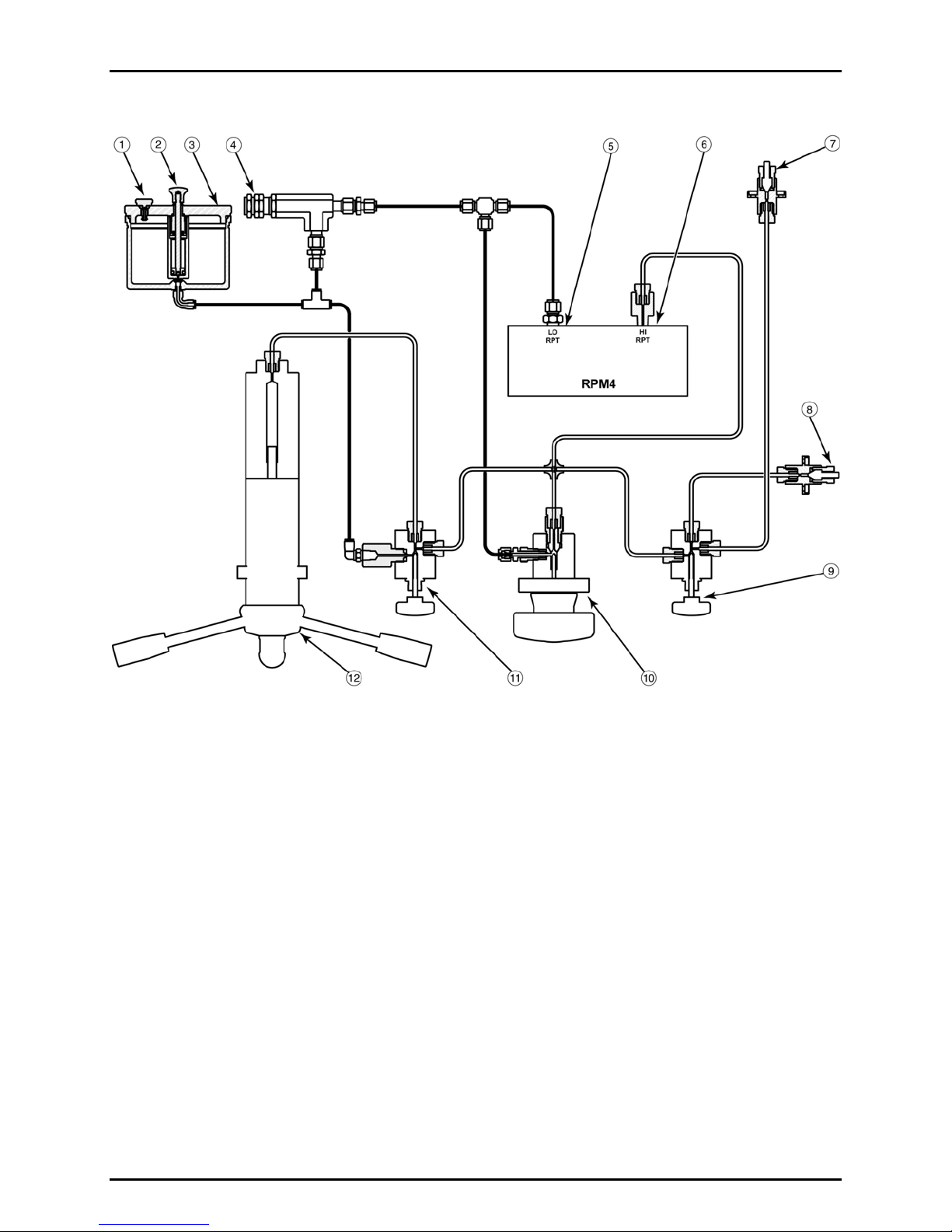
1.3.5.2 Dual Q-RPT E-DWT-H Schematic
AReservoir vent valve
B Priming pump
C Reservoir
D Lo Q-RPT pressure relief valve
E Lo Q-RPT (ref pressure transducer)
F Hi Q-RPT (ref pressure transducer)
G TEST port1 (top)
H TEST port 2 (rear)
I Test shut off and fine adjustment valve
J Lo Q-RPT shut off valve
K Reservoir shut off valve
L Variable volume (screw press)
Figure 9. E-DWT-H with dual Q-RPTs hydraulic schematic
Other manuals for E-DWT-H
1
Table of contents
Other DH Instruments Test Equipment manuals


