Chassis Plans CPC1-17 Use and care manual
CPC1-17
CPC1-19
Commercial Grade
1U Rack Mount
LCD Keyboard Console
17” or 19” SXGA LCD
Technical Reference
22009200A
Revision A
June 6, 2014

This Page Intentionally Blank

Warranty The product is warranted against material and manufacturing defects for two years from
date of delivery. Buyer agrees that if this product proves defective Chassis Plans’ is only
obligated to repair, replace or refund the purchase price of this product at Chassis Plans’
discretion. The warranty is void if the product has been subjected to alteration, neglect,
misuse or abuse; if any repairs have been attempted by anyone other than Chassis Plans;
or if failure is caused by accident, acts of God, or her causes beyond the control of Chassis
Plans. Chassis Plans reserves the right to make changes or improvements in any product
without incurring any obligation to similarly alter products previously purchased.
In no event shall Chassis Plans be liable for any defect in hardware or software or loss or
inadequacy of data of any kind, or for any direct, indirect, incidental or consequential
damages arising out of or in connection with the performance or use of the product or
information provided. Chassis Plans’ liability shall in no event exceed the purchase price
of the product purchased hereunder. The foregoing limitation of liability shall be equally
applicable to any service provided by Chassis Plans.
Return Policy Products returned for repair must be accompanied by a Return Material Authorization
(RMA) number, obtained from Chassis Plans prior to return. Freight on all returned items
must be prepaid by the customer, and the customer is responsible for any loss or damage
caused by common carrier in transit. Items will be returned from Chassis Plans via
Ground, unless prior arrangements are made by the customer for an alternative shipping
method
To obtain an RMA number, call us at 858-571-4330. We will need the following
information:
Return company address and contact
Model name and model # from the label on the back of the display
Serial number from the label on the back of the display
Description of the failure
An RMA number will be issued. Mark the RMA number clearly on the outside of each box,
include a failure report for each board and return the product(s) to our San Diego, CA
facility:
Chassis Plans.
10123 Carroll Canyon Road
San Diego, CA 92131
Attn: Repair Department

Trademarks “The Original Industrial Computer Source”, “Systems Engineered to Perform” and Chassis
Plans are registered trademarks of Chassis Plans, LLC.
IBM, PC/AT, VGA, EGA, OS/2 and PS/2 are trademarks or registered trademarks of
International Business Machines Corp.
Intel is a registered trademark of Intel Corporation.
MS-DOS and Microsoft are registered trademarks of Microsoft Corp.
All other brand and product names may be trademarks or registered trademarks of their
respective companies.
Liability
Disclaimer This manual is as complete and factual as possible at the time of printing; however, the
information in this manual may have been updated since that time. Chassis Plans
reserves the right to change the functions, features or specifications of their products at
any time, without notice.
Copyright © 2014 by Chassis Plans. All rights reserved.
E-mail: Support@chassisplans.com
Web: www.chassisplans.com
Chassis Plans
10123 Carroll Canyon Road • San Diego, CA 92131

Chassis Plans CPC-17, -19 Technical Reference Index
Table of Contents
Chapter1‐Introduction___________________________________________________1
Description_______________________________________________________________________________1
Table1–DisplaySpecifications____________________________________________________________________1
GenesisBasedLCDControllers________________________________________________________________2
Table2–LCDControllerFeatures__________________________________________________________________2
FrictionSlides_____________________________________________________________________________2
MiscellaneousDesignNotes__________________________________________________________________2
Photos___________________________________________________________________________________3
FrontView____________________________________________________________________________________3
RearView–NoKVM____________________________________________________________________________3
RearView_____________________________________________________________________________________3
StandardControllerI/O__________________________________________________________________________3
4‐PortDVIKVMSwitch___________________________________________________________________________3
4‐PortVGAKVMSwitch__________________________________________________________________________3
8‐PortVGAKVMSwitch__________________________________________________________________________3
KeyboardwithTrackBall_________________________________________________________________________3
KeyboardwithTouchPad________________________________________________________________________3
Specifications______________________________________________________________________________4
Enclosure________________________________________________________________________________________4
17”Display______________________________________________________________________________________4
19”Display______________________________________________________________________________________4
KEYBOARD_______________________________________________________________________________________4
POWERSUPPLYOPTIONS___________________________________________________________________________4
Table3–Specifications__________________________________________________________________________4
StandardControllerDVI‐D/VGAInputFeatures:_________________________________________________________5
Table4–LCDControllersSpecifications_____________________________________________________________5
Figure1‐CPCw/oKVMSwitchOutlineDrawing______________________________________________________6
Figure2‐CPCw/KVMSwitchOutlineDrawing_______________________________________________________7
Chapter2–KVMSwitchOptions____________________________________________8
KVMSwitchOptions________________________________________________________________________8
DirectConnectionversusComboCables________________________________________________________8
Figure3–ConsoleCableInstallationDiagram________________________________________________________8
4‐PortDVI(OrderOption‘C’)________________________________________________________________________9
Photo1–4‐PortDVI‐DSwitchRearView____________________________________________________________9
4‐PortVGA(OrderOption‘A’)_______________________________________________________________________9
Photo2–4‐PortVGARearView___________________________________________________________________9
8‐PortVGA(OrderOption‘B’)______________________________________________________________________10
Photo3–8‐PortVGARearView__________________________________________________________________10
16‐PortVGA(OrderOption‘E’)_____________________________________________________________________11
Photo4–16‐PortVGARearView_________________________________________________________________11
16‐PortSwitchDaisyChainInstallations______________________________________________________________12
16‐PortSwitchBasicOperation______________________________________________________________12
16‐PortSwitchHotPlugging________________________________________________________________________12
16‐portSwitchChangingStationPositions____________________________________________________________12

Chassis Plans CPC-17, -19 Technical Reference Index
16‐portswitchHotPluggingKVMPorts_______________________________________________________________12
16‐portswitchHotPluggingConsolePorts____________________________________________________________12
16‐portswitchPortSelection_______________________________________________________________________12
16‐portswitchPortIDNumbering___________________________________________________________________12
16‐portswitchPoweringOffandRestarting___________________________________________________________13
16‐portswitchUSBPeripheralDevices_______________________________________________________________13
Chapter3–OrderingInformation____________________________________________________________15
PartNumberMatrix______________________________________________________________________________15
ExamplePartNumbers____________________________________________________________________________15
Chapter4‐Installation___________________________________________________17
PackageContents________________________________________________________________________________17
Table5‐PackageContents______________________________________________________________________17
RackInstallation__________________________________________________________________________18
Figure4‐RackMountingHoleSpacing_____________________________________________________________18
ConnectingtheDisplay_____________________________________________________________________19
StandardControllerRearPanelConnections(NoKVMSwitch)_____________________________________19
Photo5–StandardControllerRearPanelI/O________________________________________________________19
Table6‐RearPanelConnections–StandardController_______________________________________________19
Chapter5‐Operation____________________________________________________21
LCDFrontPanelControls___________________________________________________________________21
Table7‐FrontPanelControls____________________________________________________________________21
StandardControllerOSDMenus_____________________________________________________________22
Table8‐StandardControllerOSDMenus___________________________________________________________23
Chapter7–KVMProgramming____________________________________________25
KVMKeyboardAccess______________________________________________________________________25
4‐PortDVIKVMSwitchOperatingInstructions________________________________25
Keyboardhotkey_________________________________________________________________________________25
Table9–4‐PortDVIKVMQuickGuide_____________________________________________________________26
4‐PortVGAKVMSwitchOperatingInstructions_______________________________27
Overview_______________________________________________________________________________________27
PortSwitching___________________________________________________________________________________27
CyclingThroughthePorts__________________________________________________________________________27
Table10–CyclingThroughthePorts______________________________________________________________27
GoingDirectlytoaPort____________________________________________________________________________27
Table11–GoingDirectlytoaPort________________________________________________________________27
AutoScanning___________________________________________________________________________________28
Table12–AutoScanningCommands______________________________________________________________28
HotkeySettingMode_____________________________________________________________________________28
InvokingHSM___________________________________________________________________________________28
AlternateHSMInvocationKeys_____________________________________________________________________29
AlternatePortSwitchingKeys______________________________________________________________________29
KeyboardLanguage_______________________________________________________________________________29
KeyboardOperatingPlatform_______________________________________________________________________29
Table13–KeyboardOperatingPlatform___________________________________________________________29
ListSwitchSettings_______________________________________________________________________________30
USBReset______________________________________________________________________________________30
HotkeyBuzzerControl_____________________________________________________________________________30

Chassis Plans CPC-17, -19 Technical Reference Index
DisablePortSwitchingKeys________________________________________________________________________30
RestoreDefaultSettings___________________________________________________________________________30
VideoDynaSync__________________________________________________________________________________30
MousePort‐switching_____________________________________________________________________________30
MouseEmulationControl__________________________________________________________________________31
KeyboardEmulationControl________________________________________________________________________31
OtherOSMode__________________________________________________________________________________31
HSMSummaryTabl e______________________________________________________________________________31
Table14–HSMSummaryTable__________________________________________________________________31
8‐PortVGAKVMSwitchOperatingInstructions_______________________________32
AccessingandUsingtheOSDMenus_________________________________________________________________32
Table15–MainOSDMenuFunctions______________________________________________________________32
Figure5–MainOSDWindow____________________________________________________________________32
Table16–Navigatingthe8‐PortKVMOSDMenu____________________________________________________32
Table17–MainOSDMenuFunctions______________________________________________________________32
Figure6–SetupOptionsWindow_________________________________________________________________33
Table18–SetupMenuFunctions_________________________________________________________________33
16‐PortVGAKVMSwitchOperatingInstructions______________________________34
OSDOverview___________________________________________________________________________________34
OSDLogin______________________________________________________________________________________34
OSDHotkey_____________________________________________________________________________________34
OSDMainScreen________________________________________________________________________________34
Figure7–16‐PortSwitchOSDMainMenu__________________________________________________________34
OSDMainScreenHeadings________________________________________________________________________35
Table19–16‐PortSwitchOSDMainScreenHeadings_________________________________________________35
16‐PortVGAKVMSwitchOSDNavigation______________________________________________________35
OSDFunctions___________________________________________________________________________________35
F1:GOTO_______________________________________________________________________________________36
F2:LIST________________________________________________________________________________________36
Table20–F2:ListFunction______________________________________________________________________36
F3:SET_________________________________________________________________________________________37
Table21–F3:SetFunction______________________________________________________________________37
F4:ADM________________________________________________________________________________________38
Table22–F4:ADMFunction_____________________________________________________________________39
F5:SKP_________________________________________________________________________________________39
F6:BRC________________________________________________________________________________________40
F7:SCAN_______________________________________________________________________________________40
F8:LOUT_______________________________________________________________________________________40
16‐PortVGAKVMSwitchHotkeyPortControl__________________________________________________41
InvokeHotkeyMode______________________________________________________________________________41
NumberLockandMinusKeys_______________________________________________________________________41
ControlandF12Keys_____________________________________________________________________________41
SelecttheActivePort_____________________________________________________________________________42
AutoScanMode_________________________________________________________________________________42
InvokingAutoScan:______________________________________________________________________________42
SkipMode______________________________________________________________________________________43
Table23–SkipMode___________________________________________________________________________43
ComputerKeyboard/MouseReset__________________________________________________________________43
HotkeyBeeperControl____________________________________________________________________________43
QuickHotkeyControl_____________________________________________________________________________44
OSDHotkeyControl______________________________________________________________________________44
PortOSControl__________________________________________________________________________________44

Chassis Plans CPC-17, -19 Technical Reference Index
Table24–PortOSControl_______________________________________________________________________44
RestoreDefaultValues____________________________________________________________________________44
HotkeySummaryTa b le____________________________________________________________________________45
Table25–16‐PortVGAKVMSwitchHotkeySummaryTable____________________________________________45
ThisPageIntentionallyBlank_____________________________________________________________________46
AppendixA–DisplaySerialControlProgramming___________________________47
RS‐232Serialcontrol_______________________________________________________________________47
StandardControllerSerialControlFunctions___________________________________________________47
Table26‐StandardControllerCommandstoImplementSwitchMountControlButtons_____________________47
Table27‐StandardControllerParameterSetting‐Immediate,Relative,ResetandQuery____________________48
Table28‐StandardControllerOtherControl________________________________________________________49
AdvancedControllerSerialControlFunctions___________________________________________________50
Table29‐AdvancedControllerCommandstoImplementSwitchMountControlButtons____________________50
Table30‐AdvancedControllerParameterSetting‐Immediate,Relative,ResetandQuery___________________50
Table31‐AdvancedControllerOtherControl_______________________________________________________57
Table32‐HextoASCIIConversionTable___________________________________________________________58
AppendixB–AutoColorGain______________________________________________59
ImageB‐1–AutoColorGainExample______________________________________________________________59
AppendixC–DVI‐DVersusDVI‐IConnectors_________________________________61
Overview________________________________________________________________________________61
Connectors_______________________________________________________________________________61

Chassis Plans CPC1-17, -19 Technical Reference Chapter 1 - Introduction
Page 1
Chapter 1 - Introduction
Description
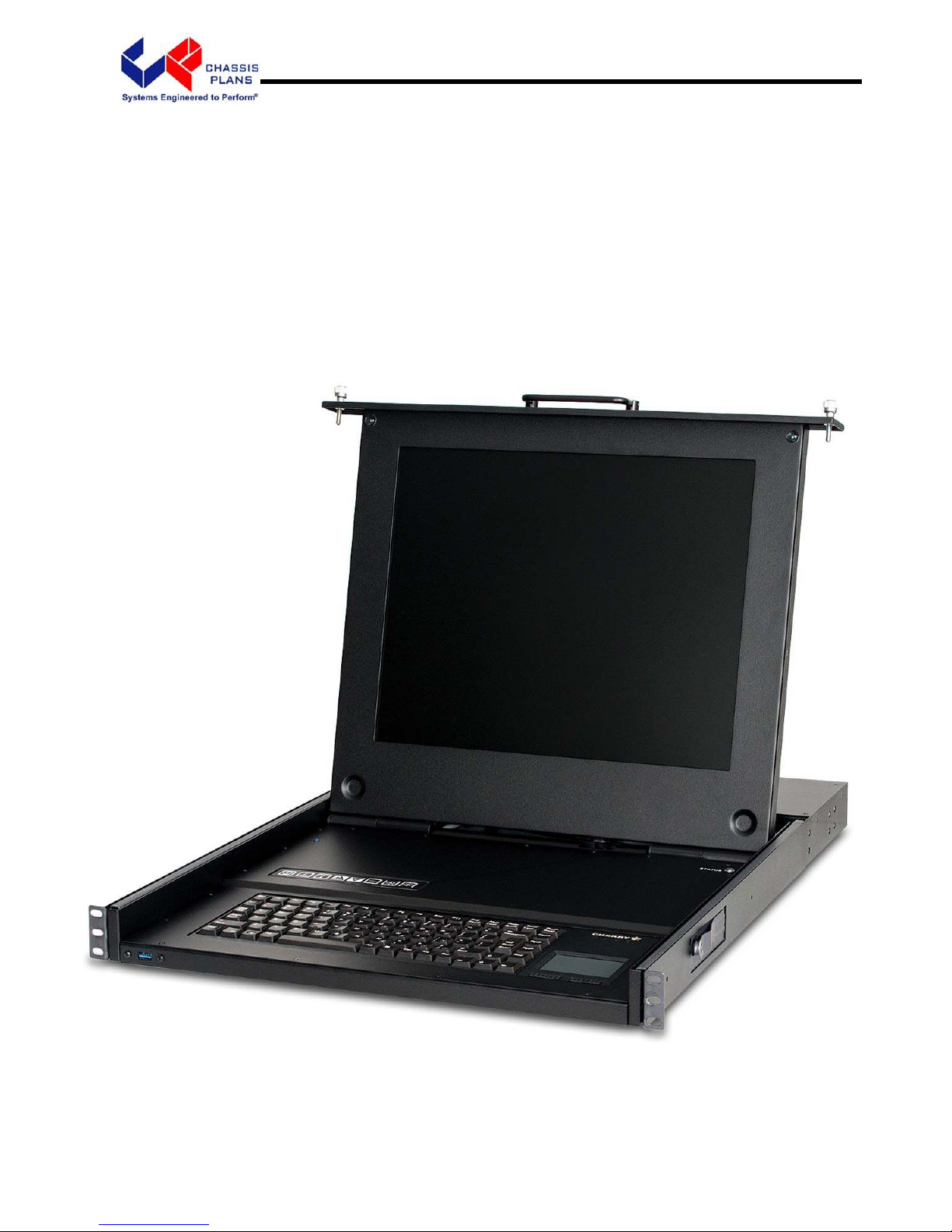
The CPC1-17 and –19 are commercial grade high performance 1U clamshell LCD keyboard drawers offering 17-
inch and 19-inch TFT LCD displays and full-travel keyboards. The front panel provides a USB port. The drawer
is held closed by two captive thumb screws and lock out friction slides are included. The CPC is ideal for use in
commercial applications where the quality of a US manufactured product and long product availability is
advantageous.
CPC1-17 17” LCD CPC1-19 19”
LCD
Contrast Ratio 1000:1 1000:1
Viewing Angle (L/R/U/D) 80º 80º
Response Time 30ms 5ms
Brightness 350 cd/m
2
350 cd/m
2
Backlight LED LED
Native Resolution 1280 x 1024 1280 x 1024
Aspect Ratio 5:4 5:4
Table 1 – Display Specifications
The 17” and 19” LCD displays are high performance, long life TFT LCD’s offering a maximum native resolution
of 1280x1024 with 16.7 million colors (True Color). The displays have a hard-coat anti-glare finish applied.
The displays offer a high quality advanced scaling controller with a Genesis chipset. The Standard Controller
offers DVI-D and VGA (aRGB) inputs. Other controllers are optionally available with different feature sets and
inputs.
The keyboard is full-travel, provides 88 keys, offers a choice of trackball or touch pad and supports PS/2 or USB
outputs.
The front panel provides a USB port.
Optionally available are built-in 4-, 8- and 16-port VGA or 4-port DVI-D KVM switches.
The components are revision controlled and offer long life product availability for assured delivery throughout
multi-year programs.
As with all Chassis Plans products, a wide variety of custom options can be configured per customer or
application specific requirements. Contact your Sales Engineer to discuss your particular requirements.

Chassis Plans CPC1-17, -19 Technical Reference Chapter 1 - Introduction
Page 2
Genesis Based LCD Controllers
The LCD Controller is a key component in any display system
and no expense has been spared in specifying the Standard
Genesis controller. These are long life revision controlled
components. The Genesis chip set is the current gold standard
for LCD controllers. The controllers support 3x8-bit 16.7 million
colors scaled to 1280x1024 native panel resolution. Refresh
rates of 60Hz for UXGA and SXGA with higher refresh rates for
lower resolutions available. Computer input signals of VGA,
SVGA, XGA, and SXGA are supported. DVI inputs supports up
to 1280x1024 60Hz signals.
The Standard Controller provides up scaling. This allows input
scaling of virtually any lower-resolution input signal to scale the
image to the 1280x1024 native LCD panel resolution. They
provide for PC, Apple and Sun input resolutions.
The Standard Controller provides DVI-D inputs.
Friction Slides
Rugged General Devices friction slides have been specified.
Ball bearing slides are a weak point in any rackmount keyboard
design and the use of friction slides negates those problems.
Using friction slides allows the keyboard to stay at the position
you place it without the use of troublesome lock-outs. Friction
slides also have a very high tolerance for dust and dirt that
typically destroys ball bearing slides in very short order.
Included in the kit are rack adapter brackets allowing installation
into racks from 24- to 36-inch depth. Also included is all
required hardware to install the keyboard assembly into a rack.
Cage nuts are also supplied.
Miscellaneous Design Notes
1. Front Panel USB
The front panel USB port is not available on the unit with the 16-port KVM switch installed. There is no
room on the rear panel for the output port.
2. PS/2 Keyboard and Pointing Device
The PS/2 output signal for the Keyboard and Pointing Device is not available on the unit with no KVM
switch installed. This unit only supports USB.
Table 2 – LCD Controller Features

Chassis Plans CPC1-17, -19 Technical Reference Chapter 1 - Introduction
Page 3
Photos
Front View
Rear View – No KVM
Rear View
Standard Controller I/O
4-Port DVI KVM Switch
4-Port VGA KVM Switch
8-Port VGA KVM Switch
16-Port VGA KVM Switch
Keyboard with Touch Pad
Keyboard with Track Ball
Chassis Plans CPC1-17, -19 Technical Reference Chapter 1 - Introduction
Page 4
Specifications
Enclosure
1U (1.71”) x 22.0” (No KVM) or 23.9” (w/ KVM) deep
18ga cold rolled steel
All stainless steel hardware
All self-locking pressed in fasteners where
appropriate
Powder coat black, medium texture, for ruggedness
Other colors optionally available
Compact Enclosure for Limited Depth Installation
Weight: 18-21lbs (depending on model & features)
17” Display
17" TFT LCD 1280x1024
Display Colors: 16.7 Million
Response Time: 30ms Typical
Viewing Angle: 80 deg
Contrast Ratio: 1000:1 typical native
Brightness: 350cd/m2 typical
Pixel Pitch: 0.264mm x 0.264mm
Pixel Arrangement: R.G.B Stripe
Operating Temperature: 0 to + 50 Deg C
Storage Temperature: -20 to +60 Deg C
19” Display
19" TFT LCD 1280x1024
Display Colors: 16.7 Million
Response Time: 5ms
Viewing Angle: 80 deg
Contrast Ratio: 1000:1 typical native
Brightness: 350cd/m2 typical
Pixel Pitch: 0.297mm x 0.297mm
Pixel Arrangement: R.G.B. Stripe
Operating Temperature: 0 to + 50 Deg C
Storage Temperature: -20 to +60 Deg C
KEYBOARD
88 keys
Trackball or touchpad pointing device
USB or PS/2 (by model number)
POWER SUPPLY OPTIONS
AC Input
100 to 260VAC, auto selecting
47-66 HZ
Table 3 – Specifications
Chassis Plans CPC1-17, -19 Technical Reference Chapter 1 - Introduction
Page 5
Standard Controller DVI-D/VGA Input Features:
Inputs:
Analog RGB: 60Hz at SXGA, WXGA, XGA,
SVGA, VGA
With auto detect of Digital
Separate Sync, Sync-On-Green &
Composite Sync. Auto detects
VGA ~SXGA interlaced &
noninterlaced.
DVI-D: 60Hz at SXGA, WXGA, XGA,
SVGA, VGA
Image Scaling: Up scaling to fit input to panel
resolution.
Image Control: Brightness, Contrast, Saturation,
Hue, Frequency, Phase, Color
temperature, Image position, Hue,
Gamma.
Other Features: Auto picture setup, Auto RGB cali-
bration, Auto source seek, OSD
timeout, OSD position, Input
source select, OSD menu lock,
Direct key for brightness level
adjustment.
Table 4 – LCD Controllers Specifications

Chassis Plans CPC1-17, -19 Technical Reference Chapter 1 - Introduction
Page 6
Figure 1 - CPC w/o KVM Switch Outline Drawing
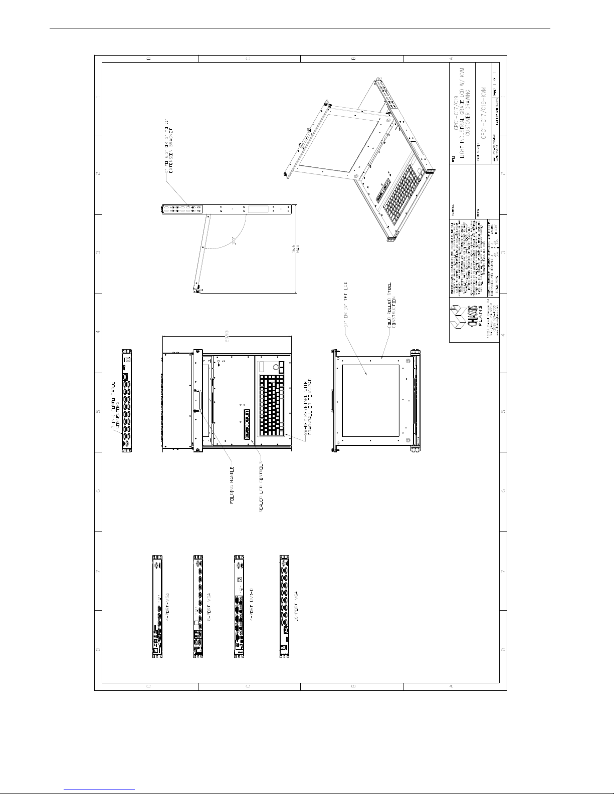
Chassis Plans CPC1-17, -19 Technical Reference Chapter 1 - Introduction
Page 7
Figure 2 - CPC w/ KVM Switch Outline Drawing

Chassis Plans CPC1-17, -19 Technical Reference Chapter 2 – KVM Switch Options
Page 8
Chapter 2 – KVM Switch Options
KVM Switch Options
The CPC1-17 and CPC1-19 are offered with built-in KVM switches offering 4-, 8- or 16-ports of VGA video with
PS/2 or USB keyboard/pointing device outputs or 4-ports of DVI-D with USB outputs. These are feature rich
switches offering hot-key control, On Screen Display (OSD) control, and firmware upgrade capability.
Direct Connection versus Combo Cables
Depending on the installed KVM Switch, connecting your computers to the rear of the CPC keyboard may be
either direct as with the 4-port DVI/USB switch or through Combo Cables in the case of the 4-, 8- and 16-port
VGA switches.
The VGA switches provided custom high-density DB-15 connectors on the rear panel to which the combo cables
are connected. The other end of the combo cable provides the VGA video connector, PS/2 mouse and
keyboard connectors and USB connector(s) for connection to your computers.
NOTE
The connectors for the Combo Connectors labeled “Computer x” where ‘x’ is the port number look
like VGA connectors but are not. Forcing a VGA connector onto these Combo Cable connectors
may damage one or both of these connectors.
The 4-port DVI-D switch provides for direct connection to the rear of the KVM for DVI-D and USB.
Figure 3 – Console Cable Installation Diagram
Chassis Plans CPC1-17, -19 Technical Reference Chapter 2 – KVM Switch Options
Page 9
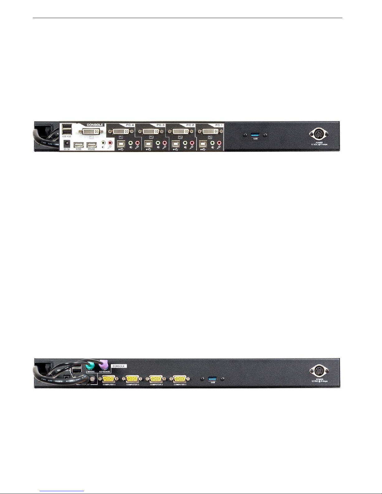
4-Port DVI (Order Option ‘C’)
The DVI Switch provides four ports of DVI-D and USB 2.0 connection to the CPC family LCD display consoles.
In addition, each port is provided with speaker out and microphone/audio input although the CPC does not
provide built-in speakers. A 2-port USB 2.0 Hub is included for connecting additional devices. The KVM
supports USB PC’s, Mac G3/G4, iMac and Sun. Hot plugging is provided so devices can be connected or
disconnected while other devices are in use. Auto scanning is also provided. Power is provided by the USB
connection to a connected computer so external power is not normally required though it can be provided for
unusual USB configurations or power requirements. A 6-foot cable set is provided for connection to one
computer. Other cables and lengths are optionally available.
Photo 1 – 4-Port DVI-D Switch Rear View
4-Port VGA (Order Option ‘A’)
The 4-Port VGA KVM Switch is a simple VGA only KVM providing four ports of VGA interface with PS/2 or USB
connectivity. The KVM supports USB PC’s, Mac G3/G4, iMac and Sun. Hot plugging is provided so devices can
be connected or disconnected while other devices are in use. Control is via Hotkey keystroke combinations and
the very latest in mouse port-switching – simply double-click on the scroll wheel of a USB mouse to change
ports. Secure access can be configured with password protection. Programmable autoscan is provided. A
single 6-foot 3-in-1 cable for connecting to one computer’s VGA port and keyboard/mouse (via PS/2 or USB) is
provided. Additional cables and length options are available. Power is provided by the computer’s PS/2 or USB
ports and a separate AC power brick providing +9VDC is provided for stand-alone operation.
The switch comes with patented Video DynaSync™ technology, which eliminates boot-up display problems and
optimizes resolution, and features dual console keyboard and mouse ports, meaning any combination of PS/2 or
USB keyboard and mouse can be used.
The single USB port on the rear panel is a pass-through from the front panel USB connector. The USB ports in
the Console section would be used when a USB keyboard is installed in the CPC. The Console USB ports and
PS/2 ports can be used at the same time. The front panel USB connector can be routed through the switch’s
USB ports to the connected computers allowing a USB device plugged into the front panel to connect to any
selected computer.
Only KVM cable sets which are specifically designed to work with this switch may be used to link to the
computers. See “Direct Connection Versus Combo Cables” above.
Photo 2 – 4-Port VGA Rear View

Chassis Plans CPC1-17, -19 Technical Reference Chapter 2 – KVM Switch Options
Page 10
8-Port VGA (Order Option ‘B’)
The 8-port switch is an 8-port keyboard, video and mouse (KVM) switch that supports both USB and PS/2
interfaces. With the capacity to daisy-chain up to 16 levels, the 8-port switch also allows direct channel selection
via two different methods: on-screen display (OSD) or keyboard hotkeys.
Time-out and password protection offer secure access to the 8-port switch, while the hot-plug feature allows for
uninterrupted switching and usage.
Only KVM cable sets which are specifically designed to work with this switch may be used to link to the
computers. See “Direct Connection Versus Combo Cables” above.
Power can be provided by the computer’s PS/2 or USB ports when only a couple of the ports are in service. If
more than four ports are in use, the included 9V external power supply should be connected.
Photo 3 – 8-Port VGA Rear View
8-Port VGA Switch Installation
If you are installing your 8-port switch to a PS/2 interface, you must power down all servers before connecting
your switch to a server to ensure proper installation. USB interfaces do not need to be powered down before
installation.
PS/2 and USB interfaces cannot be used simultaneously.
NOTE: Linux users may experience mouse failure if hot-plugging directly to the 8-port switch. If your mouse
becomes locked, use the mouse reset hotkeys to reset your mouse, or turn the Linux server off before
connecting it to the 8-port switch.
Plug one end of the supplied power cord into the back of the switch and the other end into an appropriate power
source. Connect the local keyboard, monitor and mouse cables to the appropriate ports on the rear of the 8-port
switch.
Connect your servers to an available port on the rear of your 8-port switch using the cable appropriate for your
interface. Power up all connected servers. Keyboard and mouse recognition is now activated and your 8-port
switch is ready for operation.

Chassis Plans CPC1-17, -19 Technical Reference Chapter 2 – KVM Switch Options
Page 11
16-Port VGA (Order Option ‘E’)
A single 16-port switch can control up to 16 computers. As many as 31 additional switches can be daisy chained
to each other, so that up to 512 computers can all be controlled from a single keyboard-monitor-mouse console.
A custom ASIC provides an auto-sensing function that recognizes the position of each station on the chain,
eliminating the need to manually set the position with DIP switches.
For further convenience, the 16-port switch features high density SPHD connectors instead of the usual 25-pin
connectors. This space-saving innovation allows a full, 16-port switch, to be installed in a 1U system rack.
Additionally, a front panel USB port is available for each computer to access any peripherals connected to it on a
one-at-a-time basis.
Setup is fast and easy; plugging cables into their appropriate ports is all that is entailed. The 16-port switch
supports both USB and PS/2 connections for the console and computers; and because the 16-port switch
intercepts keyboard inputs directly, there is no software to configure, so there is no need to get involved in
complex installation routines or be concerned with incompatibility problems.
Access to any computer connected to the installation is easily accomplished either entering hotkey combinations
from the keyboard, or by means of a powerful menu driven multilingual on-screen display (OSD) system. A
convenient auto-scan feature also permits automatic scanning and monitoring of the activities of all computers
running on the installation on a one at a time basis.
By allowing a single console to manage all the attached computers, a CPC KVM with a 16-port switch
installation: eliminates the expense of having to purchase a separate keyboard, monitor, and mouse for each
computer; saves all the space those extra components would take up; saves on energy costs; and eliminates the
inconvenience and wasted effort involved in constantly moving from one computer to another..
Photo 4 – 16-Port VGA Rear View
16-Port VGA Switch Installation
For convenience and flexibility that allows mixing PS/2 and USB interfaces, the 16-port switch
design utilizes
custom KVM cables that serve as intermediaries between the KVM switch and the connected computers.
Single Level Installation
In a single level installation, there are no additional switches daisy chained down from the first unit. To set up a
single level installation do the following:
Make sure that power has been turned off to all the computers you will be connecting up.
Using the console cable provided, connect a keyboard, mouse, and monitor to the 16-port switch
console port.
Refer to the Cable Connection Diagrams on the following page.
Use KVM cable sets to connect any available KVM port to the keyboard, video and mouse ports of the computer
you are installing. Refer to the KVM Cable Installation Diagrams on the following page.
Plug the power adapter cable into the 16-port switch
power jack, then plug the power adapter into an AC power
source.

Chassis Plans CPC1-17, -19 Technical Reference Chapter 2 – KVM Switch Options
Page 12
16-Port Switch Daisy Chain Installations
To control even more computers, up to 31 additional switches can be daisy chained down from the first CPC with
16-port KVM switch. As many as 512 computers can be controlled from a single console in a complete
installation. Contact your Chassis Plans Sales Engineer for instructions for this implementation.
16-Port Switch Basic Operation
16-Port Switch Hot Plugging
The 16-port switch supports hot plugging – components can be removed and added back into the installation by
unplugging their cables from the ports without the need to shut the unit down. In order for hot plugging to work
properly, however, the procedures described below must be followed:
16-port Switch Changing Station Positions
You can change a station’s position by simply disconnecting it from its master and reconnecting it to another
switch in the chain. In order for the OSD menus to correspond to the change, the station IDs must be reset in the
OSD. See RESET STATION IDS, page 32 for details.
16-port switch Hot Plugging KVM Ports
In order for the OSD menus to correspond to KVM port changes, you must manually reconfigure the OSD to
reflect the new port information. See the F3 SET and F4 ADM, functions for details.
Note: If the computer's operating system does not support hot plugging, this function may not work properly.
16-port switch Hot Plugging Console Ports
The keyboard, monitor, and mouse can all be hot plugged. When hot plugging the mouse:
You may unplug and replug the mouse (to reset the mouse, for example), as long as you use the same mouse.
If you plug in a different mouse, all the stations and all the computers on the installation must be shut down for
10 seconds, then restarted following the power up sequence.
Note: If, after hot plugging there is no response to keyboard and/or mouse input, perform a Keyboard and
Mouse Reset by simultaneously pressing the 1 and 2 front panel port LEDs.
16-port switch Port Selection
The 16-port switch provides three port selection methods to access the computers on the installation: Manual, an
OSD (on-screen display) menu system, and Hotkeys.
16-port switch Port ID Numbering
Each KVM port on a 16-port switch installation is assigned a unique port ID. The port ID is made up of two parts:
a Station Number, and a Port Number:
The Station Number is a two digit number of the switch's position in the daisy chain sequence. This number is
displayed on the front panel station ID LED.
The Port Number is a two digit number of the port on the 16-port switch station that a computer is connected to.
The station number precedes the port number.
Station and port numbers from 1–9 are padded with a preceding zero, so they become 01–09.
For example, a computer attached to Port 6 of Station 12 would have a port ID of: 12-06.
This manual suits for next models
1
Table of contents
Popular Network Hardware manuals by other brands

Alpha Shield
Alpha Shield INTERNET PRIVACY PROTECTION Manual Del Usuario

sugar-valley
sugar-valley NetBus RS2NET user guide

Checkpoint
Checkpoint Smart-1 225 Getting started guide

Black Box
Black Box ICOMP user guide

Black Box
Black Box SW1009A manual
 Series user manual")
HIK VISION
HIK VISION DeepinMind iDS-6700NXI-I/8F(B) Series user manual


