Chauvet Stage Designer 50 TFX-48B User manual

Chauvet, 3000 N 29th Ct, Hollywood, FL 33020 U.S.A.
(800) 762-1084 –(954) 929-1115
FAX (954) 929-5560
www.chauvetlighting.com
Stage Designer™50
TFX-48B
USER MANUAL
Snapshot
Ok on Dimmer
Outdoor OK
Sound Activated
DMX512
Master/Slave
115V/230V Switch
Replaceable Fuse
User Serviceable
Duty Cycle

Stage Designer™ 50 User Manual 2 Revised: 2008-08-25 16:16:53
TABLE OF CONTENTS
1. Before You Begin................................................................................................................................3
What is included .......................................................................................................................................3
Unpacking Instructions..............................................................................................................................3
Safety Instructions ....................................................................................................................................3
2. Introduction.........................................................................................................................................4
Features...................................................................................................................................................4
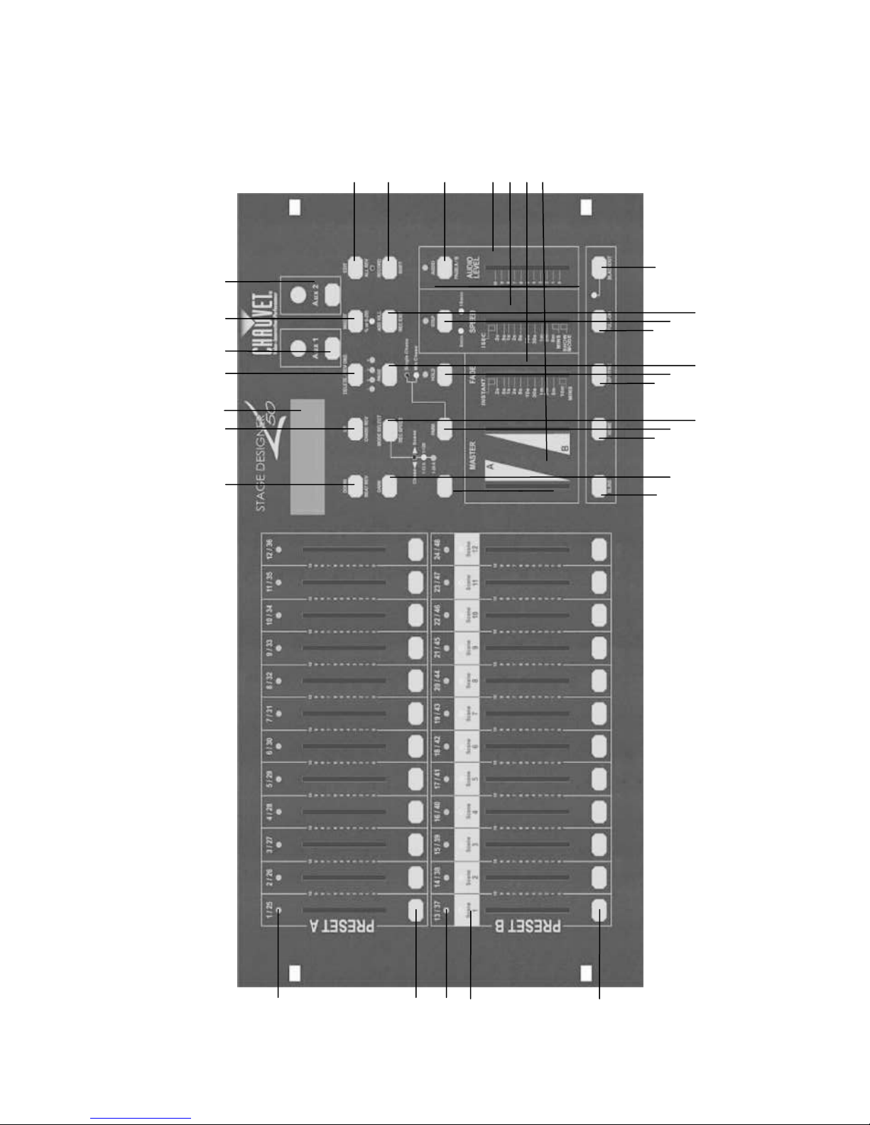
Product Overview (front)............................................................................................................................5
Product Overview (rear panel)...................................................................................................................6
Common Terms........................................................................................................................................8
3. Operating Instructions........................................................................................................................ 9
Setup........................................................................................................................................................9
Setting up the System...............................................................................................................................9
Physical fader Assignment (optional setup)................................................................................................ 9
Switching between Page and Page B (Channels 1-24 and 25-48)...............................................................9
4. Programming..................................................................................................................................... 10
Entering program mode (record enable)................................................................................................... 10
Create a scene ....................................................................................................................................... 10
Edit Enable............................................................................................................................................. 10
Erase a Program.....................................................................................................................................11
Erase all Scenes..................................................................................................................................... 11
Record Clear ..........................................................................................................................................11
Delete a step or steps ............................................................................................................................. 12
Insert a Step or Steps ............................................................................................................................. 12
Modify a Step or Steps............................................................................................................................ 12
5. Playback............................................................................................................................................ 13
Playing a Scene......................................................................................................................................13
Playing a Scene to audioTriggering .........................................................................................................13
Playing a Scene with the Speed slider..................................................................................................... 14
Plating a Scene with the Standard beat....................................................................................................14
Change the Speed mode between 5 & 10minutes................................................................................... 14
Auxiliary controls..................................................................................................................................... 15
Midi Operation........................................................................................................................................16
Setting MIDI IN ....................................................................................................................................... 16
Setting MIDI OUT....................................................................................................................................17
Receiving MIDI File Dump.......................................................................................................................17
Sending MIDI File Dump ......................................................................................................................... 17
6. Appendix........................................................................................................................................... 18
DMX Primer............................................................................................................................................18
Fixture Linking........................................................................................................................................ 18
Returns Procedure.................................................................................................................................. 19
Claims.................................................................................................................................................... 19
Troubleshooting......................................................................................................................................19
DMX Dipswitch Quick Reference Chart....................................................................................................20
General Troubleshooting.........................................................................................................................20
Technical Specifications..........................................................................................................................24

TFX-48B User Manual 3 Revised: 2008-08-25 16:16:53
1. BEFORE YOU BEGIN
What is included
Stage Designer™50 controller
DC 9-12V 500mA, 100-240v autoswitching
Manual with warranty card
Unpacking Instructions
Immediately upon receiving a fixture, carefully unpack the carton, check the contents to ensure that
all parts are present, and have been received in good condition. Notify the shipper immediately and
retain packing material for inspection if any parts appear damaged from shipping or the carton itself
shows signs of mishandling. Save the carton and all packing materials. In the event that a fixture
must be returned to the factory, it is important that the fixture be returned in the original factory box
and packing.
Safety Instructions
Please keep this User Guide for future consultation. If you sell the unit to another user, be sure that
they also receive this instruction booklet.
Always make sure that you are connecting to the proper voltage and that the line voltage you are
connecting to is not higher than that stated on decal or rear panel of the fixture.
This product is intended for indoor use only!
To prevent risk of fire or shock, do not expose fixture to rain or moisture. Make sure there are no
flammable materials close to the unit while operating..
In the event of serious operating problem, stop using the unit immediately. Never try to repair the unit
by yourself. Repairs carried out by unskilled people can lead to damage or malfunction. Please
contact the nearest authorized technical assistance center. Always use the same type spare parts.
Don’t connect the device to a dimmer pack.
Make sure power cord is never crimped or damaged.
Never disconnect power cord by pulling or tugging on the cord.
Do not operate this device in more than 104°F (40°C) ambient temperature conditions.
Caution! There are no user serviceable parts inside the unit. Do not open the housing or attempt
any repairs yourself. In the unlikely event your unit may require service, please contact
CHAUVET at: 954-929-1115.
Please read these instructions carefully, which includes important information
about the installation, usage and maintenance of your fixture.

TFX-48B User Manual 4 Revised: 2008-08-25 16:16:53
2. INTRODUCTION
The Stage Designer 50™ is a universal intelligent lighting controller. It allows the control of 48 channels with
96 scene/chase playback faders. Each scene/chase can contain up to 1000 individual steps, or looks. On the
surface, when in the CHASE◄►SCENE mode, there are 12 physical faders for the playback of the saved
programs. There are 4 pages of Scenes playback on Page A, and an additional 4 pages of playback faders on
Page B. Programs can be triggered by music, midi, automatically or manually. Channel assignments can be
reprogrammed for ease of controlling different fixtures. On the surface you will find various programming tools
such as 24 channels fader, A/B master faders for cross mixing, and Fade and Speed time faders for on the fly
adjustments. And it also has an LED display for easy navigation of controls and menu functions.
Features
Universal DMX-512 controller
Controls up to 48 DMX channels
8 pages of 12 playbacks faders,
6 sets of chases containing 240 scenes
Program fade and speed time into each step
Reversible sliders
Re-assignable channels
Sequential linking of chases
Assignable joystick
Fog & strobe control buttons
Grab any fixture on the fly
Beat activation, tap-sync and auto run
Polarity selector
6 space (6U) 19" rack mount
MIDI compatible

Stage Designer™ 50 User Manual 5 Revised: 2008-08-25 16:16:53
Product Overview (front)
21
2
5
7
8
15
12
6
4
13
1
20
3
16
10
9
18
11
19
22
23
24
25
26
27
28
29
30
31
32
14

TFX-48B User Manual 6 Revised: 2008-08-25 16:16:53
Item
Button or Fader
Function
1
Channel Faders
Indicates channels 1-12(25-36)
2
Channel Flash button
Brings the relevant fader to 100% or DMX value of 255
3
Channel Faders
Indicates channels 13-24(37-48)
4
Scene Playback
indicators
Indicates that the scene is playing back
5
Channel Flash button
Brings the relevant fader to 100% or DMX value of 255
6
Down/Beat Rev
Down functions to modify a scene in Edit mode, Beat Rev is used to reverse the
chasing direction of a program with regular beat
7
Up/Chase Reverse
Up function to modify a scene in Edit mode, Chase Reverse is used to reverse
the chasing direction of a program under Speed Slider control.
8
LCD Display
Shows the current activity or programming state
9
Delete/Rev One
Delete a step in a scene or reverse he chasing direction of any program
10
Aux 1
Patchable; used to control a channel in 1 of 2 modes of operation
11
Insert/%or255
Insert is to add 1 step or steps into a scene; %or255 is used to change the
display value cycle between % and 0-255
12
Aux 2
Patchable; used to control a channel in 1 of 2 modes of operation
13
Edit/All Rev
Edit is used to activate Edit mode; All Rev is to reverse the chasing direction of
all programs
14
Record/Shift
Record is used to activate Record mode or program a step; Shift functions the
alternate function of other buttons only
15
Audio/Page A_B
Audio activate audio sync of chase; Page A_B switches the channel faders
BETWEEN 1-24 MODE AND 25-48 MODE. Press and hold Record & Page A_B
to switch between the 2 channel pages.
16
Blind
Takes the channel out of a program temporarily in Chase◄►Scene mode
18
Dark
Used to temporarily blackout overall output
19
Home
Used to deactivate the Blind on a given channel
20
Park
Used to select Single/Mix Chase, bring Channel 13-24(37-48) to full of current
setting, or momentarily program a scene into Master B slider depending on the
current mode.
21
Mode Select/Rec
Speed
Used to activate the operating mode; Rec Speed sets the speed of any
programs chasing in Mix mode
22
Tap Sync
Repeatedly tapping this button will establish the chase speed
23
Hold
Used to momentarily maintain current scene
24
Page
Tap to select pages of scenes from 1-4(Page A) and 1-4 (Page B)
25
Full On
Momentarily bring all channels (1-48) to full intensity
26
Step
Used to go to the next step when the Speed slider is set in Show Mode or in Edit
mode.
27
Add Kill/Rec exit
In Add mode, multiple scenes or Flash buttons will be on at the same time; In Kill
mode, pressing any Flash button will kill any other scenes or programs; Rec Exit
is used to exit from Program or Edit mode.
28
Blackout
Used to kill all output, with exception of Full On.
29
Audio Level Fader
Adjusts the audio sensitivity when in Audio trigger mode of scenes
30
Speed Fader
Used to adjust the sped of scenes/chases running
31
Fade Fader
Adjusts the fade-in, fade-out, and cross-fade times
32
Master A_B
Adjusts overall intensity

Stage Designer™ 50 User Manual 7 Revised: 2008-08-25 16:16:53
Product Overview (rear panel)
8
1
7
2
3
Item
Button or Fader
Function
1
3-pin DMX output connector
DMX control signal
2
5-pin DMX output connector
DMX control signal
3
Polarity switch
Used to select DMX polarity
4
MIDI Thru
MIDI port for connecting to a sequencer or MIDI device
5
MIDI Out
MIDI port for connecting to a sequencer or MIDI device
6
MIDI In
MIDI port for connecting to a sequencer or MIDI device
7
Audio Input
This jack accepts a line level audio input signal ranging from 100mV to 1Vpp
8
Remote Input
Blackout and Full On may be controlled by a remote control using a standard ¼´jack
9
DC Input
DC 12-20V, 500mAMin.
9
4
5
6

TFX-48B User Manual 8 Revised: 2008-08-25 16:16:53
Common Terms
The following are common terms used in intelligent light programming.
Blackout is a state where all lighting fixtures’light output are set to 0 or off, usually on a temporary
basis.
DMX-512 is an industry standard digital communication protocol used in entertainment lighting
equipment. For more information read Sections “DMX Primer” and “DMX Control Mode” in the
Appendix.
Fixture refers to your lighting instrument or other device such as a fogger or dimmer which you can
control.
Programs are a number of scenes arranged one after another. It can be programmed as either a
single scene or multiple scenes in sequence.
Scenes are static lighting states.
Sliders are also known as faders.
Chases can also be called programs. A chase consists of a number of scenes arranged one after
another.
Scanner refers to a lighting instrument with a pan and tilt mirror; however DMX controllers can use
this term to control any DMX-512 compatible device as a generic fixture.
MIDI is a standard for representing musical information in a digital format. A MIDI input would provide
external triggering of scenes using midi devices such as a midi keyboard.
Stand Alone refers to a fixture’s ability to function independently of an external controller and usually
in sync to music, due to a built in microphone.
Fade slider is used to adjust the fade time between scenes within a chase.
Speed slider affects the amount of time a scene will hold its state. It is also considered a wait time.
Shutter is a mechanical device in the lighting fixture that allows you to block the lights path. It is often
used to lessen the intensity of the light output and to strobe.
Patching refers to the process of assigning faders to a DMX channel within a fixture.
Playbacks can be either scenes or chases that are directly called to execution by the user. A
playback can also be considered program memory that can be recalled during a show.

TFX-48B User Manual 9 Revised: 2008-08-25 16:16:53
3. OPERATING INSTRUCTIONS
Setup
SETTING UP THE SYSTEM
1) Place the Stage Designer 50™on a level surface. Note! The Stage Designer 50™can also be
rack mounted, occupying six rack spaces (6U).
2) Plug the AC to DC power supply into the system back panel and into the mains outlet.
3) Plug in your DMX cable(s) to your intelligent lighting as described in the respective fixture’s
manual. For a quick overview of DMX see the “DMX Primer” on page 19.
4) Reset the system using the instructions on page 11 under ERASE ALL SCENES..
PHYSICAL FADER ASSIGNMENT (OPTIONAL SETUP)
Use this feature to combine or unify fixture control attributes for different fixtures. For example; if you
were controlling 4 moving mirrors and 4 moving yokes, the color, gobo and dimmer channels may not
line up ideally on the physical faders. Use this function to re-assign the dimmer, color and gobo
channels to faders 1, 2 and 3. From now on you will be able to control the same attributes on all
fixtures using the same fader location. This is also most useful when needing to combine all colors
together.
Action
1. Press and hold RECORD button.
2. While holding the Record button, press the
Flash button #6 (3) times.
3. Press the Flash button that you wish to
assign the DMX channel output to.
4. While holding Record, press the Flash
button corresponding to the DMX output
that you wish to assign the Fader to.
5. Repeat steps 2 ~ 3 as often as necessary.
6. Press and hold Record & Rec Exit to exit
the mode.
For example: you wish to assign Fader #1 to
output to DMX channel #5.
1. Hold the Record button & press Fader#6 (3)
times.
2. Press the Flash button #1.
3. While holding the Record button, press the
Flash button #5.
Notes
All physical faders can be re-assigned to output on a
different DMX channel. Faders are given a channel
number and are labeled on the surface of the
controller as such.
You can check to see what the assignment is by
pressing the Fader button of the corresponding
channel while in this mode.
Here is no limit to the amount of channels that can be
assigned to a single fades. One can assign up to all 48
channels of DMX output to a single Fader.
CHNO corresponds to the Physical Fader, while
SLDNO corresponds to the DMX output channel.
SWITCHING BETWEEN PAGE AND PAGE B (CHANNELS 1-24 AND 25-
48)
Action
1) Press and hold Record & press Page A_B
button. If you are on Page A, then this will
bring you to Page B. If you are on Page B,
then this will bring you to Page A.
Notes
When the fixture turns on, it will revert to the
previously used page.
Page A is used to control channels 1-24, while Page B
is used to control channels 25-48.
The screen will display which current page.
There’s an additional set of 4 pages of playback
controls on Page B.

Stage Designer™ 50 User Manual 10 Revised: 2008-08-25 16:16:53
4. PROGRAMMING
ENTERING PROGRAM MODE (RECORD ENABLE)
1. While holding the RECORD button, tap the Flash buttons 1-5-6-8 in sequence.
2. Release the RECORD button. The Record LED lights up;
CREATE A SCENE
A scene is a static lighting state. Scenes are stored in the temporary memory, until they are
transferred to one of the playback faders. You may create a single scene or a succession of up to 999
steps per Scene.
Action
1) Record enable.
2) Select the 1-24 Single mode by tapping the
Mode Select button. This will give you
control of all 24 channels of the first page.
3) Compose a look by moving the FADERS.
(Changes in fixture attribute such as colors
and gobos, or simply dimmer values).
4) Press Record to save the look into the
temporary memory.
5) Repeat steps 2 ~ 4 until you have your
desired scene.
6) Adjust the Speed and Fade sliders to
achieve the desired amount of time a scene
will be held in a chase (speed) and the
amount of time allowed for the fixtures to
move from one scene to the next (fade).
7) Select a Scene master to store your scene.
Tap the Page button to select a page (1-4).
8) Press and hold the Record button & tap the
Flash button for the scene that you wish to
store it to. All LEDs will flash indicating the
scene has been programmed into memory.
9) You can continue programming or exit. To
exit program mode, press and hold the
Record button & tap the Rec Exit button.
Notes
Deselect Blackout if LED is lit.
Be sure that you are on the right page by viewing the
screen where it displays Page A or Page B. This will
enable 1-24 or 25-48 channel control.
If you just wish to create a static look, then you must
create a scene composed of only 1 step.
There are 1000 steps available in every scene.
EDIT ENABLE
Action
1) Record enable.
2) Use the Page button to select the page the
program you wish to edit is on.
3) Tap the Mode Select button to select
Chase◄►Scenes.
4) Press and hold the Edit button & tap the
Flash button (13-24) of the Scene you
wish to edit.
5) Release the Edit button. The relevant
Scene Led should light, indicating you are
in Edit mode.
Notes
When the EDIT mode is entered properly, the display
will read EDITING.
This mode is displayed here for only the initiation of
EDIT mode. Please see the following sections on the
uses of this mode in detail.

Stage Designer™ 50 User Manual 11 Revised: 2008-08-25 16:16:53
ERASE A PROGRAM
Action
1) Record enable.
2) Use the Page button to select the page the
Scene you wish to erase is on.
3) Press and hold the Edit button & tap the
Flash button (13-24) twice of the Scene you
wish to erase.
4) Release the 2 buttons. The LED for the
corresponding program should light,
indicating that it has been selected.
5) Press the Delete button. All LEDs should
light, indicating the program is erased.
Notes
ERASE ALL SCENES
Action
1) Record enable
6) Press and hold RECORD.
2) While holding Record button, tap the flash
buttons in the following sequence: 1-3-2-3.
Release the Record button.
7) All LEDs should light, indicating all
programs have been erased.
8) Press and hold RECORD & REC EXIT to
exit the mode.
Notes
You must be in Record mode to Reset the controller.
The LED over the Record button will light, indicating
the Record mode operation.
Warning: this will reset the controller to its factory defaults. This will erase all programs and settings.
RECORD CLEAR
Action
1) Record enable.
2) Record a scene with 1 or more steps.
3) If you are not satisfied with the scene, you
may press and hold the Record button &
tap the Page/REC CLR button. All LEDs will
flash, indicating the scenes have been
cleared.
Notes
All scenes stored in the temporary memory of the
controller will be erased by this process.
This process will not affect the scenes already
programmed into a Scene fader.

Stage Designer™ 50 User Manual 12 Revised: 2008-08-25 16:16:53
DELETE A STEP OR STEPS
Action
1) Enter the EDIT mode.
2) Tap the Step button to scroll to the step you
wish to delete.
3) Tap the Delete button when you reach the
step you wish to delete. All LEDs will light,
indicating the deletion of the step.
4) Repeat steps 2 and 3 until all of the
unwanted steps have been deleted.
5) Press and hold the Record & Rec Exit
button. The Scene button LED will turn off,
indicating that the Edit mode has been
exited.
Notes
INSERT A STEP OR STEPS
Action
1) Record a scene or scenes you wish to
insert.
2) Be sure you are in Chase◄►Scene and
enter the EDIT mode.
3) Tap the Step button to scroll to the step
which you wish to insert the step before.
You may read the step from the display.
4) Tap the Insert button to insert the step
you’ve created before.
5) Exit EDIT mode.
Notes
Part of entering the Edit mode is selecting which
scene you wish to Edit. See section on Edit enable for
further instructions.
All LEDs will flash to indicate a successful Insert of
the step.
MODIFY A STEP OR STEPS
Action
1) Enter EDIT mode.
2) Press and hold the Up button if you want to
raise the intensity. Press the Down button if
you want to lower the intensity.
3) Tap the Step button to scroll to the step
which you wish to insert the step before.
You may read the step from the display.
4) While holding the Up or Down button, tap
the Flash button corresponding to the DMX
channel of the Scene you wish to modify
until you reach the desired intensity value
read from the display. Then, you may tap
the Flash buttons until you are satisfied with
the new Scene.
5) Repeat steps 2, 3, and 4 until all the steps
have been modified.
6) Exit EDIT mode.
Notes
Part of entering the Edit mode is selecting which
scene you wish to Edit. See section on Edit enable for
further instructions.
All LEDs will flash to indicate a successful Insert of
the step.

Stage Designer™ 50 User Manual 13 Revised: 2008-08-25 16:16:53
5. Playback
This controller uses the Channel Faders and Channel Flash buttons for multiple uses. In this
occurrence, Channel Faders 13-24 (37-48) are used for the playing back of Scenes already recorded.
This is only when the controller is in the Chase◄►Scene mode. In this instance, Master Fader A
will control the manual fader controls, while Master Fader B will control the Scenes being played
back.
PLAYING A SCENE
A Scene can contain 1,000 steps. The term steps and scenes are used interchangeably.
Action
1) Tap the Mode Select button to select
Chase◄►Scene mode.
2) Tap the Page button to select the
correct page the program you wish to
run is located.
3) Push master Slider B to its maximum
position (fully down).
4) Move the desired Channel slider (13-
24) to its maximum, and the Scene will
fade in depending upon current fade
time.
5) Move the channel slider to adjust the
output of the current program.
Notes
The current mode is indicated by the 3 LEDs. Red is
the Chase◄►Scene. Yellow is 2-scene preset A/B.
And, Green is 1-24 single mode.
You may press and hold down the relevant Flash
button for the Scene to trigger the button
momentarily.
PLAYING A SCENE TO AUDIOTRIGGERING
Action
1) Select your Scene as described in the
above section.
2) Tap the Audio button until its LED lights,
indicating AUDIO mode is active.
3) Use the Audio Level slider to adjust the
sensitivity.
4) To return to normal mode, tap the Audio
button a second time, causing its LED to go
out. AUDIO mode is disengaged.
Notes
This is the process of using the built-in microphone,
or using the audio jack located on the rear of the
controller to use an alternative audio source for
triggering of the Scenes.

Stage Designer™ 50 User Manual 14 Revised: 2008-08-25 16:16:53
PLAYING A SCENE WITH THE SPEED SLIDER
Action
1) Select your Scene as described in the
above sections.
2) Move the Speed slider to SHOW MODE
position (fully down).
3) Press and hold the Rec Speed button & tap
the corresponding Flash button (13-24). The
Scene tapped will no longer run with the
standard beat.
4) Now, you may move the Speed slider to
select your desired speed.
Notes
Be sure AUDIO mode is disengaged.
Step #3 is not necessary if the selected Scene is not
recorded with the Standard beat.
PLAYING A SCENE WITH THE STANDARD BEAT
Action
1) Tap the Mode select button to select
Chase◄►Scene mode.
2) Tap the Park button to select Mix Chase
mode. The LED lights, indicating the
selection.
3) Select your Scene as described in the
previous sections.
4) Move the Speed slider until the display
reads your desired value.
5) Press and hold Rec Speed button & tap the
Flash button (13-24) to store the Scene.
The Scene will now run with the set time or
beat when engaged.
6) Repeat steps 4 & 5 to set a new beat time.
Notes
Be sure AUDIO mode is disengaged.
As an alternative to using the Speed slider to input the
speed, you may use the Tapsync button (2) times to
define your beat.
CHANGE THE SPEED MODE BETWEEN 5 & 10 MINUTES
Action
1) Press and hold the Record button.
2) Tap the Flash button 5 or 10 () times while
holding down the Record button.
3) The 5min or 10min Led should light,
indicating the Speed the slider is set to run.
Notes

Stage Designer™ 50 User Manual 15 Revised: 2008-08-25 16:16:53
AUXILIARY CONTROLS
This is the process of assigning the Auxiliary controls. These will act as shortcuts and are most
commonly used for DMX strobe lights or DMX fog machines. However, they are not limited to these
functions, such as Pan/tilt control-very useful for remote followspot controls.
Action
1) Press & hold RECORD & tap the Flash
button 7 or 8 (3) times. The display should
indicate activation of the mode.
2) There are 3 functions. FUNC 1 states that
the Auxiliary control is not assigned to any
channel. FUNC 2 refers o the auxiliary
controls working much like the channel
fader along with the flash buttons. FUNC 3
is somewhat different. The rotary knob acts
to set the total output of the flash button
below it.
3) While holding down the RECORD button,
select the function you wish for the auxiliary
control by pressing Flash button 1, 2, or 3.
Release the buttons.
4) To assign the auxiliary to a channel, press
the Flash button for the channel you wish to
assign the auxiliary control to. This sets the
channel assignment. The corresponding
Led above the channel will light, indicating
that the channel has ben assigned.
5) Record exit.
Notes
You may refer to the display for the functions being
edited.
Press 7 (3) times for AUX 1 patching, and 8 (3) times
for AUX 2 patching.
While assigning an auxiliary to mode 2, the Fader for
that channel will not function. It will act as moving
the channel.
While assigning an auxiliary to mode 3, the channel
fader and the auxiliary controls will both work for
that channel on an HTP (highest takes precedent)
operating principle.

Stage Designer™ 50 User Manual 16 Revised: 2008-08-25 16:16:53
Midi Operation
The controller will only respond to MIDI commands on the MIDI channel that it is assigned to. All MIDI
control is performed using Note on commands. All other MIDI instructions are ignored. To stop a
chase, send the blackout on note.
Setting MIDI IN
Action
1) While holding down the RECORD button,
simultaneously tap Flash button #1 three
times. The display reads MIDI CHANNEL
IN to indicate channel setup is available.
2) Select the MIDI control channel (1~16) by
tapping Flash buttons 1~16. The relevant
channel LED lights indicating MIDI IN
channel is set.
3) While holding down RECORD, tap the
REC EXIT button to exit MIDI setting.
Notes
This is the Channel that the controller will receive
MIDI note commands.
MIDI NOTE
FUNCTION (TURN ON/OFF)
27-69
Turn on or off program 1-48
70-93
Activate Channel 1-24
94
FULL-ON
95
DARK (momentary blackout)
96
HOLD
97
Turn on or off AUDIO
98
MODE: CHASE◄ ►SCENE
99
MODE: 1-12A_1-12B
100
MODE: 1-24A
101
Step
102
BLACKOUT
Note: When working with MIDI notes 22-93, you may simulate a fader’s increase and decrease
by adjusting the velocity of the note.

Stage Designer™ 50 User Manual 17 Revised: 2008-08-25 16:16:53
Setting MIDI OUT
Receiving MIDI File Dump
Sending MIDI File Dump
Action
4) While holding down the RECORD button,
simultaneously tap Flash button #2 three
times. The display reads MIDI CHANNEL
OUT to indicate channel setup is available.
5) Select the MIDI control channel (1~16) by
tapping Flash buttons 1~16. The relevant
channel LED lights indicating MIDI OUT
channel is set.
6) While holding down RECORD, tap the
REC EXIT button to exit MIDI setting.
Notes
This is the Channel that the controller will transmit
MIDI note commands.
Action
7) While holding down the RECORD button,
simultaneously tap Flash button #3 three
times. The display reads MIDI FILEDUMP
RECVING 000% when the device is in the
correct mode.
8) While holding down RECORD, tap the
REC EXIT button to exit MIDI setting.
Notes
This is the process of copying your entire show to
another TFX-48B. This will not work with any other
device.
This process can take several minutes to complete.
The controller will automatically begin sending the
FILE DUMP once the mode has been selected.
Therefore, be sure that the other device has previously
been setup to receive the transfer.
During FILE DUMP, all other operations will cease to
function.
If errors or power failure occurs, FILE DUMP will be
interrupted and stop.
Action
9) While holding down the RECORD button,
simultaneously tap Flash button #4 three
times. The display reads MIDI FILEDUMP
SENDING 000% when the device is in the
correct mode.
10) While holding down RECORD, tap the
REC EXIT button to exit MIDI setting.
Notes
This is the process of copying your entire show to
another TFX-48B. This will not work with any other
device.
This process can take several minutes to complete.
The controller will automatically begin sending the
FILE DUMP once the mode has been selected.
Therefore, be sure that the other device has previously
been setup to receive the transfer.
During FILE DUMP, all other operations will cease to
function.
If errors or power failure occurs, FILE DUMP will be
interrupted and stop.

TFX-48B User Manual 18 Revised: 2008-08-25 16:16:53
6. APPENDIX
DMX Primer
There are 512 channels in a DMX-512 connection. Channels may be assigned in any manner. A
fixture capable of receiving DMX 512 will require one or a number of sequential channels. The user
must assign a starting address on the fixture that indicates the first channel reserved in the controller.
There are many different types of DMX controllable fixtures and they all may vary in the total number
of channels required. Choosing a start address should be planned in advance. Channels should
never overlap. If they do, this will result in erratic operation of the fixtures whose starting address is
set incorrectly. You can however, control multiple fixtures of the same type using the same starting
address as long as the intended result is that of unison movement or operation. In other words, the
fixtures will be slaved together and all respond exactly the same.
DMX fixtures are designed to receive data through a serial Daisy Chain. A Daisy Chain connection is
where the DATA OUT of one fixture connects to the DATA IN of the next fixture. The order in which
the fixtures are connected is not important and has no effect on how a controller communicates to
each fixture. Use an order that provides for the easiest and most direct cabling. Connect fixtures
using shielded two conductor twisted pair cable with three pin XLR male to female connectors. The
shield connection is pin 1, while pin 2 is Data Negative (S-) and pin 3 is Data positive (S+). CHAUVET
carries 3-pin DMX compliant cables, DMX-10 (33’), DMX-4.5 (15’) and DMX-1.5 (5’)
FIXTURE LINKING
Note! If you use a controller with a 5 pin DMX output connector, you will need to use a 5
pin to 3 pin adapter. Chauvet Model No: DMX5M.
The chart below details a proper cable conversion:
3PIN TO 5PIN CONVERSION CHART
CONDUCTOR
3 Pin Female (output)
5 Pin Male (Input)
GROUND/SHIELD
Pin 1
Pin 1
DATA (-)SIGNAL
Pin 2
Pin 2
DATA (+)SIGNAL
Pin 3
Pin 3
DO NOT USE
Do not use
DO NOT USE
Do not use
COMMON
DMX +
DMX -
INPUT
OUTPUT
1
3
2
1
3
2
1
3
2
Resistance 120
ohm 1/4w between
pin 2 (DMX -) and
pin 3 (DMX +) of
the last fixture.
Termination reduces signal errors and to
avoid signal transmission problems and
interference, it is always advisable to connect
a DMX signal terminator.
Figure 1 - DMX connector configuration

Stage Designer™ 50 User Manual 19 Revised: 2008-08-25 16:16:53
Returns Procedure
Returned merchandise must be sent prepaid and in the original packing, call tags will not be issued.
Package must be clearly labeled with a Return Authorization Number (RA #). Products returned
without an RA # will be refused. Call CHAUVET and request an RA # prior to shipping the fixture. Be
prepared to provide the model number, serial number and a brief description of the cause for the
return. Be sure to properly pack fixture, any shipping damage resulting from inadequate packaging is
the customer’s responsibility. CHAUVET reserves the right to use its own discretion to repair or
replace product(s). As a suggestion, proper UPS packing or double-boxing is always a safe method
to use.
Note: If you are given an RA #, please include the following information on a piece of paper
inside the box:
1) Your name
2) Your address
3) Your phone number
4) A brief description of the symptoms
Claims
Damage incurred in shipping is the responsibility of the shipper; therefore the damage must be
reported to the carrier upon receipt of merchandise. It is the customer's responsibility to notify and
submit claims with the shipper in the event that a fixture is damaged due to shipping. Any other claim
for items such as missing component/part, damage not related to shipping, and concealed damage,
must be made within seven (7) days of receiving merchandise.
Troubleshooting
Please refer to the troubleshooting chart on the following page. If you still have a problem after trying
those solutions, please contact CHAUVET Technical Support at (954) 929-1115.

Stage Designer™ 50 User Manual 20 Revised: 2008-08-25 16:16:53
General Troubleshooting
Symptom
Solution(s)
Applies to
Lights
Foggers
& Snow
Controllers
Dimmers&
Chaser
Auto shut off
Check fan thermal switch reset
Beam is very dim
or not bright
Clean optical system or replace lamp
Check 220/110v switch for proper setting
Breaker/Fuse
keeps blowing
Check total load placed on device
Chase is too slow
Check users manual for speed adjustment
Device has no
power
Check for power on Mains.
Check device’s fuse. (internal and/or external)
Fixture is not
responding
Check DMX Dip switch settings for correct
addressing
Check DMX cables
Check polarity switch settings
Fixture is on but
there is no
movement to the
audio
Make sure you have the correct audio mode on
the control switches. If audio provided via ¼”
jack, make sure a live audio signal exists
Adjust sound sensitivity knob
Lamps cuts off
sporadically
Possible bad lamp or fixture is overheating.
Lamp may be at end of its life.
Light will not come
on after power
failure
Some discharge lamps require a cooling off
period before the electronics in the fixture can
kick start it again, wait 5 to 10 minutes before
powering up
Loss of signal
Use only DMX cables
Install terminator
Note: Keep DMX cables separated from power
cables or black lights.
Moves slow
Check 220/110v switch for proper setting
No flash
Re-install bulb, may have shifted in shipping
No laser output
Bounce mirror motor may have shifted during
shipping, readjust
No light output
Check slip ring & brushes for contact
Install bulb
Call service technician
Relay will not work
Check reset switch
Check cable connections
Remote does not
work
Make sure connector is firmly connected to
device
Stand alone mode
All Chauvet lighting fixtures featuring stand-
alone functions do not require additional
settings, simply power the fixture and it will
automatically enter into this mode
Table of contents
Other Chauvet Control Unit manuals
Popular Control Unit manuals by other brands

american flame
american flame AF-4000 Series manual

Parker
Parker 60VM4071 Operation and maintenance manual

Bernecker + Rainer
Bernecker + Rainer 4XP0000.00-K64 Technical documentation

AVANCIS
AVANCIS PowerMax SMART Series Safety, installation, and operation manual

Ammara Designs
Ammara Designs PBS-RGH installation instructions

Siemens
Siemens PM250 Hardware installation manual