CHD Elektroservis 8-452 User manual

7
Model 8-452
ver. 2.0
USER GUIDE
© 2014 CHD Elektroserv is
CR78-PGM
Programmer & Controller for Roland CR-78
Model 8-452 ver. 2.0
Copyri ght © 2014 CHD Elektroservis
All rights reserved. No part of this publication may be reproduced in any form without written permission of CHD Elektroservis.
2
Content page
1. Controller description . . . . . . . . . . . . . . . . . . . . . . . . . . . . . . . . . . 3
2. Controller connection . . . . . . . . . . . . . . . . . . . . . . . . . . . . . . . . . . 4
3. Controller operation . . . . . . . . . . . . . . . . . . . . . . . . . . . . . . . . . . . 5
3.1. Working mode selection . . . . . . . . . . . . . . . . . . . . . . . . . . . . . . . . . 5
4. “PLAY“ working mode . . . . . . . . . . . . . . . . . . . . . . . . . . . . . . . . . . 5
4.1. Selection of synchronization source . . . . . . . . . . . . . . . . . . . . . . . . . . 5
4.1.1. Manual synchronization . . . . . . . . . . . . . . . . . . . . . . . . . . . . . . . . . 5
4.1.2. Synchronization with MIDI bus . . . . . . . . . . . . . . . . . . . . . . . . . . . . . . 6
4.1.3. Synchronization with DIN-SYNC bus . . . . . . . . . . . . . . . . . . . . . . . . . . 6
5. “PGM“ working mode . . . . . . . . . . . . . . . . . . . . . . . . . . . . . . . . . . 7
5.1. Programming mode on CR-78 . . . . . . . . . . . . . . . . . . . . . . . . . . . . . . 7
5.2. Sequence of “step by step” programming . . . . . . . . . . . . . . . . . . . . . . . . 8
5.3. Sequence of programming in real time . . . . . . . . . . . . . . . . . . . . . . . . . 10
6. Warranty condition . . . . . . . . . . . . . . . . . . . . . . . . . . . . . . . . . . . . 11
7. Technical specification . . . . . . . . . . . . . . . . . . . . . . . . . . . . . . . . . . 11
Manufacturer :
CHD Elektroservis
Nad kundratkou 27, 19000 Praha 9
Czech Republic
info@chd-el.cz
www.chd-el.cz
CR78-PGM
Programmer & Controller for Roland CR-78
Model 8-452 ver. 2.0
Copyri ght © 2014 CHD Elektroservis
All rights reserved. No part of this publication may be reproduced in any form without written permission of CHD Elektroservis.
3
1. CONTROLLER DESCRIPTION
CR78-PGM is programmer and controller for Roland CR-78 drummachine. With help of it, CR-78
can be programmed very easy (by similar way as with original Roland WS-1 programmer). More over,
CR78-PGM enables to control CR-78 during playback manually or via MIDI or DIN -SYNC buses.
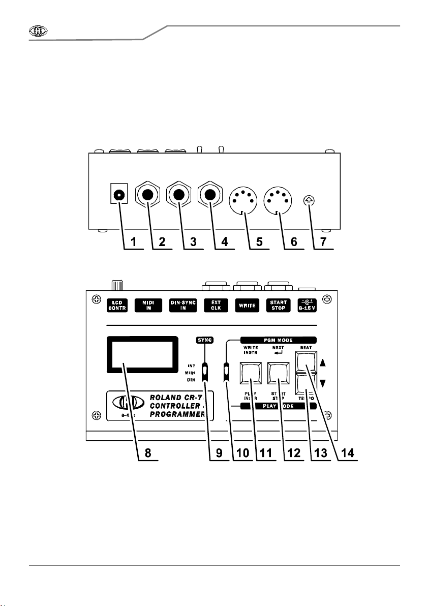
Pic. 1 – Panels of the device
Rear panel
Top panel
[1] Power supply connector DC [8] Display
[2] START/STOP signal output [9] Synchronization selector – SYNC switch
[3] W RITE signal output [10] Working mode selector – MODE switch
[4] CLOCK signal output [11] PLAY / WRITE INSTRUM ENT button
[5] DIN-SYNC bus input [12] START-STOP / NEXT button
[6] M IDI bus input [13] DECREM ENT button
[7] LCD contrast setting [14] INCREMENT button
CR78-PGM
Programmer & Controller for Roland CR-78
Model 8-452 ver. 2.0
Copyri ght © 2014 CHD Elektroservis
All rights reserved. No part of this publication may be reproduced in any form without written permission of CHD Elektroservis.
4
2. CONTROLLER CONNECTION
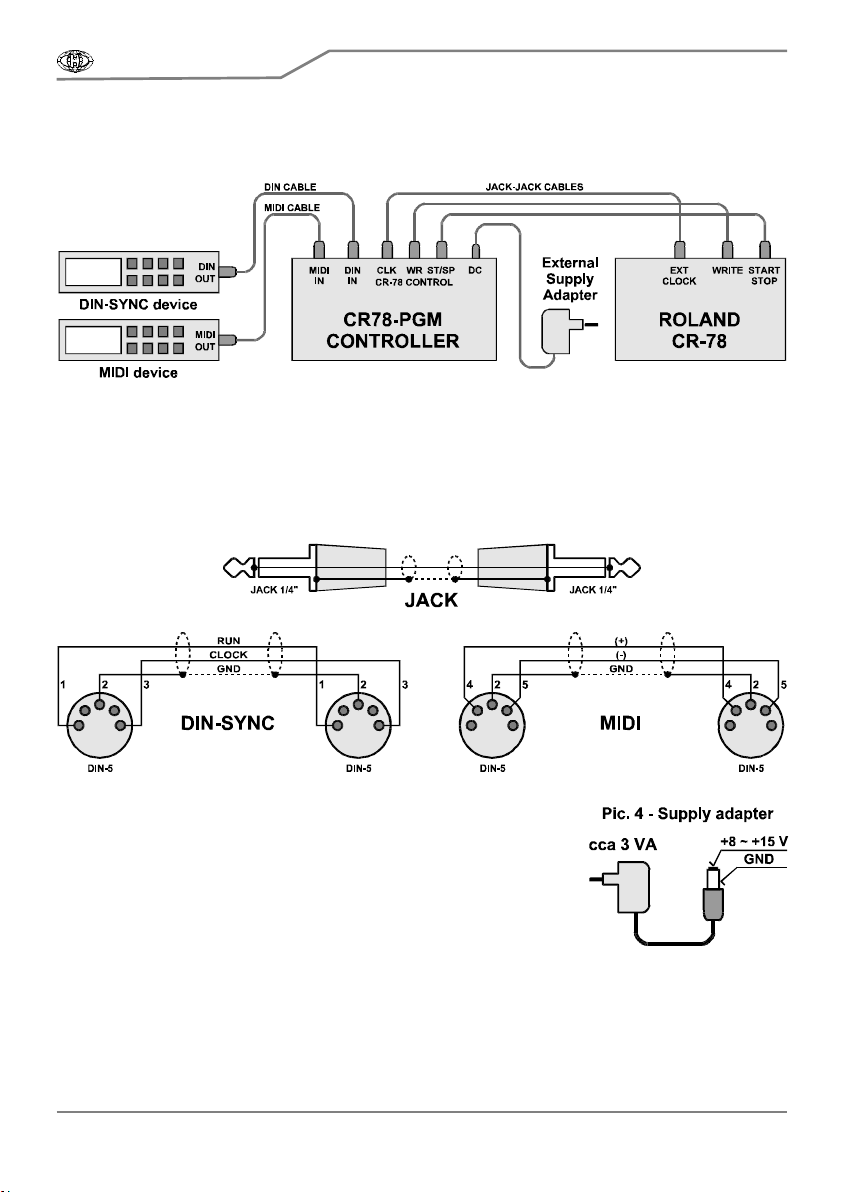
Pic. 2 – Connection of the device
Pic. 2 shows complete connection of the controller into the system. Schematics of used cables
are shown in pic. 3.
If synchronization with MIDI and/or DIN-SYNC bus is not used, corresponding cable(s) stay
unconnected at all.
Pic. 3 – Cables for connection
The device is powered from external supply adapter. DC voltage
from the adapter is connected to DC power supply connector [1]. It is
standard coaxial connector (diameter 6 / 2,1 mm). External power
supply must be able to provide at least 200 mA at 8 - 15 volt. DC
voltage needn’t to be stabilized.
The positive pole must be on inner pin, the negative on the
external pin of the connector – see pic.4. The polarity is also depicted
on panel of the device. The controller is protected against wrong polarity
of supply voltage. The device does not work in such case, but it will not
be damaged.
CR78-PGM
Programmer & Controller for Roland CR-78
Model 8-452 ver. 2.0
Copyri ght © 2014 CHD Elektroservis
All rights reserved. No part of this publication may be reproduced in any form without written permission of CHD Elektroservis.
5
3. CONTROLLER OPERATION
The device is not equipped with power switch. It works immediately after a supply adapter is
connected. After connection with CR-78, it is necessary to turn on the controller first (to connect supply
adapter to the controller). Now reset sequence will begin. During reset, display [8] shows
name of the device and number of operational system version. After reset sequence,
CR-78 can be turned on yet (by “POWER“ switch on its panel).
All information about actual status of the device are displayed on display [8] during operation.
Contrast of the display viewing can be set with LCD-CONTR [7] knob on rear panel.
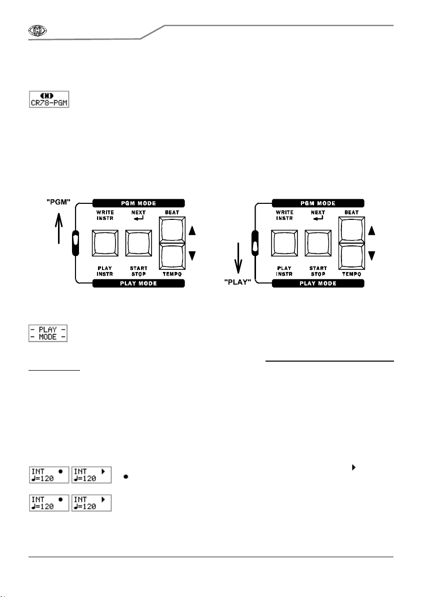
3.1. WORKING MODE SELECTION
Requested working mode of the device can be selected by MODE [10] switch – “PLAY“ for
playback (lower position) or “PGM“ for programming of user memories of CR-78 (upper position of the
switch).
4. “PLAY“ WORKING MODE
After PLAY mode is selected by MODE [10] switch, display [8] shows info about working
mode change shortly and then the controller comes into playback mode.
In PLAY mode, the device controls tempo of CR-78 and its START/STOP function.
Method of control depends on selected synchronization source. “TEMPO“ knob on CR-78’s panel is
not functional !
4.1. SELECTION OF SYNCHRONIZATION SOURCE
CR-78 synchronization source can be selected by three-position SYNC [9] switch. It is possible
to select these sources: Manual control with help of controllers on device’s panel (upper position of
SYNC switch), synchronization with MIDI bus (middle position of SYNC switch) or synchronization with
DIN-SYNC bus (lower position of SYNC switch).
4.1.1. MANUAL SYNCHRONIZATION
In manual (internal) synchronization mode, “INT“ and “START [ ]“ / “STOP
[]“ symbols are shown in upper row of display [8], actual tempo is shown in
lower row.
Playback tempo is controlled with TEMPO INCREMENT [14] / DECREMENT
[13] buttons. Range of the tempo can be from 25 to 500 BPM (Beat per
Minute). Tempo is increased / decreased in ±1 steps if INCREMENT [14] /

CR78-PGM
Programmer & Controller for Roland CR-78
Model 8-452 ver. 2.0
Copyri ght © 2014 CHD Elektroservis
All rights reserved. No part of this publication may be reproduced in any form without written permission of CHD Elektroservis.
6
DECREMENT [13] buttons are pressed shortly. If TEMPO INCREMENT [14] / DECREMENT [13]
buttons are pressed longer time, the tempo is increased / decreased continuously during the buttons
are held.
Playback can be started and stopped with help of START / STOP [12] button. Actual status is
shown on the right in upper row of display [8]. Round symbol [ ] represents STOP status; arrow
symbol [ ] represents START status.
With help of PLAY INSTR [11] button, it is possible to run up a sound generator of CR-
78 which is selected with “INSTRUMENT SELECTOR“ rotary selector on CR-78 panel.
After the PLAY INSTR [11] button is pressed, display [8] shows info about an instrument
launching [ ] for a moment. A drum instrument can be running by this way only when CR-78 is just
playing a rhythm. It is impossible when playback is stopped.
4.1.2. SYNCHRONIZATION WITH MIDI BUS
In MIDI synchronization mode, the controller receives commands from M IDI-
IN [6] input. Only common system commands CLOCK (F8h), START (FAh),
CONTINUE (FBh) and STOP (FCh) are acceptable. All others MIDI
commands are ignored. “MID” and “START“ / “STOP“ symbols are shown in upper row of display [8].
Round [ ] represents STOP status, arrow [ ] represents START status.
Actual tempo of playback derived from MIDI CLOCK commands is displayed
in upper row of display [8] in BPM (Beat per Minute) form. Info “Slow” is
displayed if the tempo is lower than 0,6 BPM or if no MIDI CLOCK
commands are received. Info “Fast” is displayed if the tempo is higher than 999,9 BPM.
With help of INCREMENT [14] and DECREMENT [13] buttons, normal []
or doubled [ ] speed of playback tempo can be chosen.
With help of PLAY INSTR [11] button, it is possible to run up a sound generator of CR-
78 which is selected with “INSTRUMENT SELECTOR“ rotary selector on CR-78 panel.
After the PLAY INSTR [11] button is pressed, display [8] shows info about an instrument
launching [ ] for a moment. A drum instrument can be running by this way only when CR-78 is just
playing a rhythm. It is impossible when playback is stopped.
START/STOP [12] button is not used in MIDI synchronization mode at all.
4.1.3. SYNCHRONIZATION WITH DIN-SYNC BUS
In DIN-SYNC synchronization mode, the controller receives
CLOCK and
RUN signals from DIN [5] input. Signals RESET and FILL are ignored.
“DIN” and “START“ / “STOP“ symbols are shown in upper row of display [8].
Round [ ] represents STOP status, arrow [ ] represents START status.
Actual tempo of playback derived from CLOCK signal is displayed in upper
row of display [8] in BPM (Beat per Minute) form. Info “Slow” is displayed if
the tempo is lower than 0,6 BPM or if no CLOCK signal is present. Info
“Fast” is displayed if the tempo is higher than 999,9 BPM.
TEMPO INCREMENT [14] / DECREMENT [13] buttons select
type of DIN bus in accordance to number of clock pulses per
quarter note (PPQN). DIN-24 (24 PPQN) type is default setting.
This type complies with most of devices equipped with DIN-SYNC output. For the others, DIN-12 (12
PPQN) or DIN-48 (48 PPQN) types can be selected. Count of clock pulses transmitted from connected
device must be found in documentation of this device and type of DIN bus must be set in accordance
with it.
CR78-PGM
Programmer & Controller for Roland CR-78
Model 8-452 ver. 2.0
Copyri ght © 2014 CHD Elektroservis
All rights reserved. No part of this publication may be reproduced in any form without written permission of CHD Elektroservis.
7
With help of PLAY INSTR [11] button, it is possible to run up a sound generator of CR-
78 which is selected with “INSTRUMENT SELECTOR“ rotary selector on CR-78 panel.
After the PLAY INSTR [11] button is pressed, display [8] shows info about an instrument
launching [ ] for a moment. A drum instrument can be running by this way only when CR-78 is just
playing a rhythm. It is impossible when playback is stopped.
START/STOP [12] button is not used in DIN-SYNC synchronization mode.
5. “PGM“ WORKING M ODE
Programming (PGM) mode of the device enables very easy programming of CR-78’s
user memories (patterns). After PGM mode is selected (with MODE [10] switch), display
[8] shows info about working mode change shortly and then the controller comes into
programming mode.
After entering into programming mode, invitation for setting of CR-78 is shown on display
[8]. Valid setting of CR-78 must be confirmed by NEXT [12] button pressing. Now
programming procedure begins.
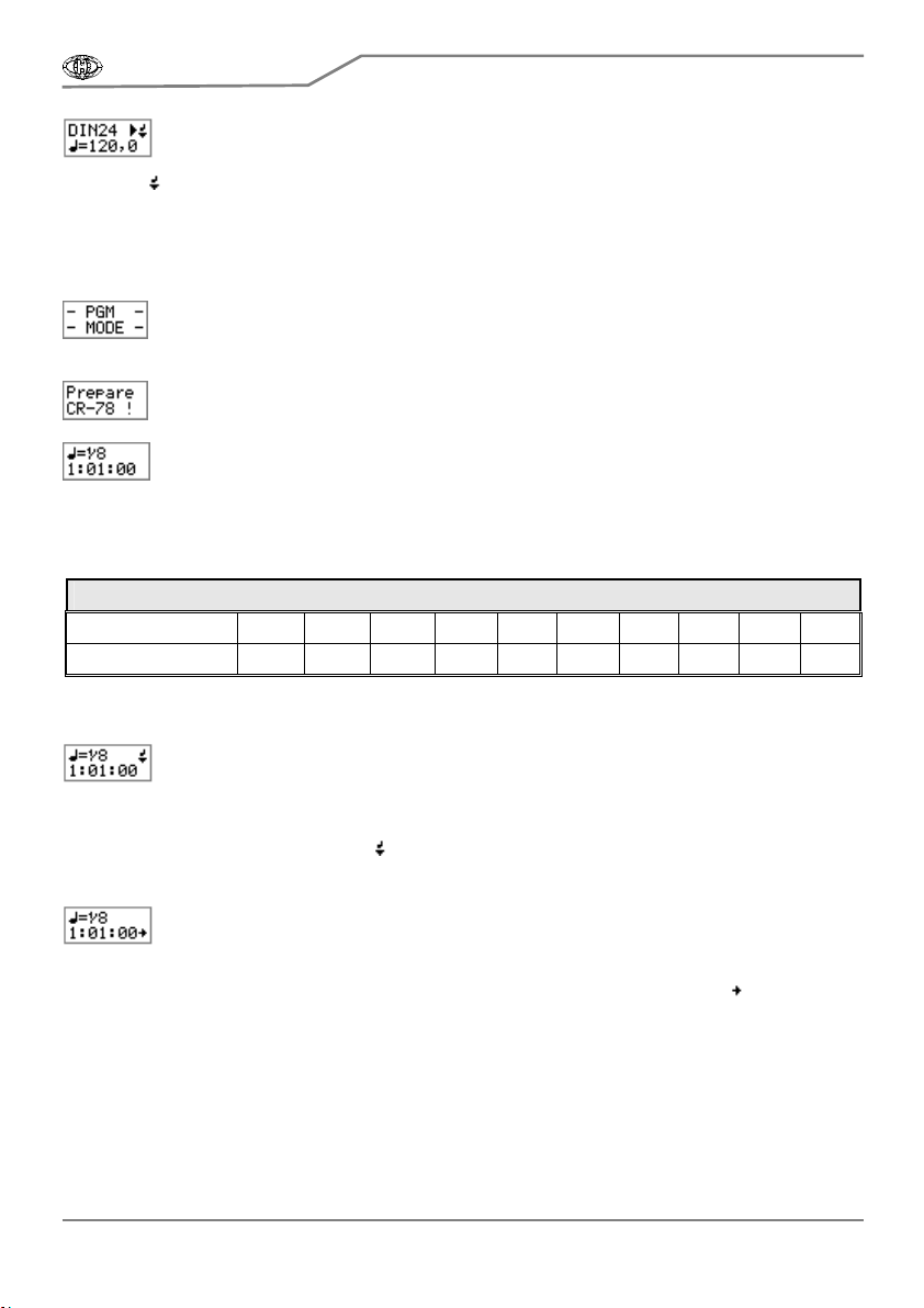
Length of programming step is displayed in upper row and actual position of
programming is displayed in lower row of display [8].
Requested length of programming step (length of Beat) can be selected with BEAT
INCREMENT [14] / DECREMENT [13] buttons. Just valid length of programming step is shown on
display [8]. Available Beats and their lengths in clock pulses (Ticks) are in table below:
Table 1 – Lengths of available Beats
Beat 1/32
3
1/16
3
1/16 1/8
3
1/8 1/4
3
1/4 1/2
3
1/2 1/1
Length [Ticks] 1 2 3 4 6 8 12 16 24 48
Actual position is displayed in M:B:T (Measure : Beat : Tick) form. Starting position (after PGM
mode is selected) is always 1:01:00.
Pressing of WRITE INSTR [11] button inserts drum instrument selected with
“INSTRUMENT SELECTOR“ selector on CR-78 panel onto actual position. Actual
position is not changed when an instrument is inserted so it is possible to insert more
instruments (up to 4, ACCENT include) onto the same position. It can be done if next instrument is
selected with “INSTRUMENT SELECTOR“ selector on CR-78 panel and then W RITE INSTR [3] button
is pressed repeatedly. Symbol of note [ ] is displayed in upper row of display [8] every time when the
button is pressed. The controller doesn’t react during the symbol is displayed – it is necessary to wait
for blackout of the symbol before next pressing of a button.
Actual position is shifted one step ahead if NEXT [12] button is pressed. Length of the
step is equal to number of clock pulses (Ticks) corresponded to duration of selected
Beat (with BEAT SLCT [2] rotary encoder – see table 1). After the position is shifted,
new actual position is shown in lower row of display [8]. Repeated pressing of NEXT [12] button
enables sequent stepping – it is equivalent to insertion of a pause. Symbol of arrow [ ] is displayed in
lower row of display [8] every time when the button is pressed. The controller doesn’t react during the
symbol is displayed – it is necessary to wait for blackout of the symbol before next pressing of a
button.
5.1. PROGRAMMING MODE ON CR-78
It is necessary to turn CR-78 to programming mode before start of CR-78’s memories
programming. Some controllers on CR-78’s panel must be set to following positions:

CR78-PGM
Programmer & Controller for Roland CR-78
Model 8-452 ver. 2.0
Copyri ght © 2014 CHD Elektroservis
All rights reserved. No part of this publication may be reproduced in any form without written permission of CHD Elektroservis.
8
• Requested memory must be selected with “PROGRAM RHYTHM“ selector. The memory can be
erased before programming if necessary.
• “PROGRAM SWITCH“ must be in “MEMORY“ position.
• Requested instrument must be selected with “INSTRUMENT SELECTOR“ rotary selector.
Note that all four user memories of CR-78 have fix length of two four-quarter measures. It is 96
clock pulses (Ticks) – CR-78 uses 12 PPQN (Pulse per Quarter Note) resolution. When length of
memory is exceeded during programming procedure, clock pulses counting starts from 1:01:00
position repeatedly. This corresponds to method of position displaying on display [8].
5.2. SEQUENCE OF “STEP BY STEP” PROGRAMMING
Example: Store rhythm on pic. 5 into user memory of CR-78.
Pic. 5 – Example of simple rhythm
Sequence:
1) Set the controller to programming mode (MODE [10] switch to “PGM“ position) and wait for display
of “Prepare CR-78 !“ invitation.
2) Select requested memory of CR-78 (“PROGRAM RHYTHM“ selector onCR-78 panel).
3) Erase selected memory of CR-78: set “PROGRAM SWITCH“ switch (on CR-78 panel) to “ALL“
position and press “CLEAR“ button (on CR-78 panel).
4) Set “PROGRAM SWITCH“ switch (on CR-78 panel) to “MEMORY“ position.
5) Confirm valid setting of CR-78 by NEXT [12] button pressing.
6) Now the programming procedure begins. First note of programmed rhythm is a quarter note – set
length of Beat to “1/4“ (with BEAT INCREMENT [14] / DECREMENT [13] buttons). Display shows
1:01:00 position (it is first quarter of first measure).
7) Select “BD” with “INSTRUMENT SELECTOR“ (on CR-78 panel) and store the instrument into CR-
78’s memory with WRITE INSTR [11] button pressing (on the controller).
8) Select “CY” with “INSTRUMENT SELECTOR“ (on CR-78 panel) and store the instrument into CR-
78’s memory with WRITE INSTR [11] button pressing (on the controller).
9) Press NEXT [12] button (on the controller) for continuing to next note. Display [8] will show 1:02:00
position (second quarter of first measure).
10) Select “CH” with “INSTRUMENT SELECTOR“ (on CR-78 panel) and store the instrument into CR-
78’s memory with WRITE INSTR [11] button pressing (on the controller).
11) Press NEXT [12] button (on the controller) for continuing to next note. Display [8] will show 1:03:00
position (third quarter of first measure).
12) Store “CH” instrument (it stays selected from previous step) with WRITE INSTR [11] button
pressing (on the controller).
13) Select “SD” with “INSTRUMENT SELECTOR“ (on CR-78 panel) and store the instrument into CR-
78’s memory with WRITE INSTR [11] button pressing (on the controller).
14) Press NEXT [12] button (on the controller) for continuing to next note. Display [8] will show 1:04:00
position (fourth quarter of first measure).
15) Next notes are 8
th
- set length of Beat to “1/8“ (with BEAT INCREMENT [14] / DECREMENT [13]
buttons). Display [8] will show 1:07:00 position (seventh 8
th
of first measure).
16) Select “CH” with “INSTRUMENT SELECTOR“ (on CR-78 panel) and store the instrument into CR-
78’s memory with WRITE INSTR [11] button pressing (on the controller).

CR78-PGM
Programmer & Controller for Roland CR-78
Model 8-452 ver. 2.0
Copyri ght © 2014 CHD Elektroservis
All rights reserved. No part of this publication may be reproduced in any form without written permission of CHD Elektroservis.
9
17) Press NEXT [12] button (on the controller) for continuing to next note. Display [8] will show 1:08:00
position (eighth 8
th
of first measure).
18) Select “BD” with “INSTRUMENT SELECTOR“ (on CR-78 panel) and store the instrument into CR-
78’s memory with WRITE INSTR [11] button pressing (on the controller).
19) Press NEXT [12] button (on the controller) for continuing to next note. Display [8] will show 2:01:00
position (first 8
th
of second measure).
20) Next notes are quarters again - set length of Beat to “1/4“ (with BEAT INCREMENT [14] /
DECREMENT [13] buttons). Display [8] will show 2:01:00 position (first quarter of second
measure).
21) Store “BD” instrument (it stays selected from previous step) with WRITE INSTR [11] button
pressing (on the controller).
22) Select “CH” with “INSTRUMENT SELECTOR“ (on CR-78 panel) and store the instrument into CR-
78’s memory with WRITE INSTR [11] button pressing (on the controller).
23) Press NEXT [12] button (on the controller) for continuing to next note. Display [8] will show 2:02:00
position (second quarter of second measure).
24) Store “CH” instrument (it stays selected from previous step) with WRITE INSTR [11] button
pressing (on the controller).
25) Press NEXT [12] button (on the controller) for continuing to next note. Display [8] will show 2:03:00
position (third quarter of second measure).
26) Store “CH” instrument (it stays selected from previous step) with WRITE INSTR [11] button
pressing (on the controller).
27) Select “SD” with “INSTRUMENT SELECTOR“ (on CR-78 panel) and store the instrument into CR-
78’s memory with WRITE INSTR [11] button pressing (on the controller).
28) Press NEXT [12] button (on the controller) for continuing to next note. Display [8] will show 2:04:00
position (fourth quarter of second measure).
29) Select “CH” with “INSTRUMENT SELECTOR“ (on CR-78 panel) and store the instrument into CR-
78’s memory with WRITE INSTR [11] button pressing (on the controller).
30) Now programming of CR-78 memory is finished. Turn “PROGRAM SWITCH“ switch on CR-78
panel to “PLAY“ position.
31) Turn the controller to playback mode (MODE [10] switch to “PLAY“ position).
32) CR-78 will replay newly programmed rhythm during next start of playback.
Any other rhythm can be programmed by similar way. The only limitation is, the shortest beat is
32
th
triplet and 32
th
note isn’t accessible at all. This limitation is given by CR-78 construction.
In some cases, this limitation can be get out by doubling of tempo during playback. It is
enabled if synchronization is INT or DIN-24 or DIN-48. But length of user memory is contracted to only
one measure in that case.
Example: Store rhythm on pic. 6 into user memory of CR-78.
Pic. 6 – Example of more difficult rhythm
Sequence:
First, rewrite the rhythm for double-speed playback:

CR78-PGM
Programmer & Controller for Roland CR-78
Model 8-452 ver. 2.0
Copyri ght © 2014 CHD Elektroservis
All rights reserved. No part of this publication may be reproduced in any form without written permission of CHD Elektroservis.
10
This rhythm can be programmed to CR-78 memory by method described above.
Set double tempo after the controller is turned back to playback mode:
• For internal synchronization (INT), set double tempo with BEAT INCREMENT [14] / DECREMENT
[13] buttons directly.
• For DIN-SYNC synchronization (DINxx), set half resolution of clock pulses than it is really transmitted
from clock source (set DIN-12 for synchronization source with PPQN = 24, set DIN-24 for source
with PPQN = 48).
5.3. SEQUENCE OF PROGRAMMING IN REAL TIME
The controller enables real time programming of CR-78’s rhythms too. This programming
method is described in owner’s manual of CR-78 (in THE OPERATION OF THE PROGRAMMER
SECTION chapter). The only difference is that manual switch TS-1 described in the user manual is not
used – it is replaced by PLAY INSTR [11] button on CR78-PGM controller.
The controller stays in playback working mode (PLAY). After setting of CR-78 (see above),
tempo generator is turned on with help of START / STOP [12] button of the controller (if internal
synchronization is selected) or from MIDI or DIN-SYNC device (if MIDI or DIN synchronization is
selected). Now instrument selected with “INSTRUMENT SELECTOR“ on CR-78’s panel is written into
CR-78’s memory every time PLAY INSTR [11] button on CR78-PGM controller is pressed.

CR78-PGM
Programmer & Controller for Roland CR-78
Model 8-452 ver. 2.0
Copyri ght © 2014 CHD Elektroservis
All rights reserved. No part of this publication may be reproduced in any form without written permission of CHD Elektroservis.
11
6. WARRANTY CONDITIONS
The equipment is provided with thirty-month warranty starting from the date of the equipment
take-over by the customer. This date must be specified on warranty list together with dealer's
confirmation.
During this period of time, all defects of equipment or its accessories, caused by defective
material or faulty manufacturing, will be removed free of charge.
Warranty repair is asserted by the customer against the dealer.
Warranty period is to be extended for the time period, during which the product was under the
warranty repair.
The relevant legal regulations take effect in case of cancellation of purchase contract.
The customer will lose the right for free warranty repair, if he will not be able to submit properly
filled out warranty list or if the defects of the product had been caused by:
- unavoidable event (natural disaster),
- connecting the device to the incorrect supply voltage,
- inputs or outputs overloading by connecting the signals source or load source with not-corresponding
characteristics etc.,
- faulty equipment operation, which is at variance with the instructions referred-to in the operating
manual,
- mechanical damage caused by consumer during transportation or usage of equipment,
- unprofessional interference with the equipment or by equipment modification without manufacturer’s
approval.
7. TECHNICAL SPECIFICATION
Power source : external supply adapter
Supply voltage : 8 V
DC
to 15 V
DC
Current consumption : 200 mA max
EXT-CLOCK output : Jack ¼“ socket (TS)
Signal : push-pull mode
Output voltage : 0 V for low level / +5V for high level
Output impedance : 47 Ω
WRITE and START/STOP outputs : Jack ¼“ socket (TS)
Signal : NC switch mode
Switched voltage : up to +15 V
Output impedance : 47 Ω for closed status / high impedance for open status
DIN-SYNC input : DIN-5 socket (pin Nr. 1: RUN signal, pin Nr. 3: CLOCK signal,
pin Nr. 2: GND, pins Nr. 4 and 5 unused)
Input voltage : 0 to +1,5 V for low level / +2,5 to +15 V for high level
Input impedance : 50 kΩ for V
IN
up to +5 V / 5 kΩ for V
IN
over +5 V
MIDI input : DIN-5 socket (pin Nr. 4: + polarity, pin Nr. 5: – polarity, pins Nr.
1, 2 and 3 unused)
Connection : standard connection – current loop 5 mA

7
Table of contents
Other CHD Elektroservis Controllers manuals


