KNX SATION-DM0101.0210 User manual

WWW.SATION.COM.CN
Technical Manual
SATION Dimming Actuator 1-fold
SATION-DM0101.0210

WWW.SATION.COM.CN
1 Overview..................................................................................................................................... 1
Diagram Drawing.........................................................................................................1
Usage...........................................................................................................................2
Structure Specification................................................................................................2
Manual operation and protection operation............................................................. 2
Function...................................................................................................................... 3
Overview of the dimming channel function.......................................................3
Universal Interface Channel Function Overview...............................................4
2 Communication Object............................................................................................................... 4
Object Corresponding Channel...................................................................................4
Channel Object............................................................................................................5
Dimming Channel Object...................................................................................6
Online State Object.............................................................................................6
The Object of the Universal Interface Channel..................................................7
Logic Object........................................................................................................7
3 ETS Parameter............................................................................................................................ 8
General Setting............................................................................................................9
Channel....................................................................................................................... 9
Function.................................................................................................................... 10
Switching.......................................................................................................... 10
Dim Relatively..................................................................................................11
Dim Absolutely................................................................................................. 11
Parameter..................................................................................................................11
Load Type......................................................................................................... 11
Time Functions................................................................................................. 12
3.4.2.1 On/Off Delay............................................................................................. 12
3.4.2.2 Staircase Light........................................................................................... 13
Absolute Values................................................................................................ 15
3.4.3.1 Starting Behavior.......................................................................................15
Dimming Area...................................................................................................17
Specific Dimming Settings...............................................................................18
3.4.5.1 Dimming Speed......................................................................................... 18
3.4.5.2 Send Dimming Value After Change.......................................................... 18
Alarm Functions............................................................................................... 19
3.4.6.1 Over Temperature Alarm........................................................................... 19
3.4.6.2 Electric Load Alarm...................................................................................20
Central Objects................................................................................................. 20
Scene Function..................................................................................................21
3.4.8.1 Submenu Scene..........................................................................................22
Automatic Function.......................................................................................... 24
Additional Functions........................................................................................ 25
3.4.10.1 Blocking Objects..................................................................................... 26
WWW.SATION.COM.CN
3.4.10.2 Behavior After Power off/after Reset......................................................27
Input Channel Configuration............................................................................ 28
3.4.11.1 The Input Channel is Configured With the Same Parameters............28
Composite Pattern Parameter Configuration....................................................29
3.4.12.1 Dimming Control.....................................................................................29
3.4.12.2 Shutter Control.........................................................................................31
3.4.12.3 Switch Control......................................................................................... 31
Independent Pattern Parameter Configuration................................................. 32
3.4.13.1 Switch...................................................................................................... 32
3.4.13.1.1 Switch Falling Edge/Rising Edge/Both Edge.............................. 33
3.4.13.1.2 Toggle Rising/Falling Edge..........................................................34
3.4.13.1.3
Send Status
...................................................................................35
3.4.13.1.4 Send Value Rising/Falling/Both Edges
...................................... 37
3.4.13.1.5 Send Value With On/Off Delay
.................................................. 39
3.4.13.2 Scene........................................................................................................41
3.4.13.3 Counter.....................................................................................................42
3.4.13.4 Switch short/long.....................................................................................44
3.4.13.5 One Button Dimming.............................................................................. 47
3.4.13.6 One Button Shutter.................................................................................. 48
LED Output
.................................................................................................... 49
Logic................................................................................................................. 50
3.4.15.1 Logic Object Type Switch
............................................................... 52
3.4.15.2 Logic Object Type Scene
................................................................. 53
3.4.15.3 Logic Object Type Byte Value
........................................................ 54
4 Contact...................................................................................................................................... 54

Copyright Clarify
Copyright ownership belongs to Zhuhai Sation Technology Co., Ltd. shall
not be reproduced, copied, or used in other ways without permission.
Otherwise Zhuhai Sation Technology Co., Ltd. will have the right to
pursue legal responsibilities.
Version
Version No.
Release Date
Description
V1.0
April 4th, 2018
1st Release
Notice
1. Please read this user manual carefully before using the product.
2. This product is used in indoor environment and installed in electrical control
box.
3. Please install this product in a dry and ventilated place.
4. Before power on, please confirm the input voltage according to the manual;
after power on, please confirm the normal output voltage before connecting to
the control bus.
5. Please make sure the secure shell is in good condition, if the shell is damaged,
please stop using to avoid accident.
6. This product is NOT a toy, please make sure it is out of children touch.
7. Only be suitable for EIB/KNX system bus.
8. Others:
The below sign indicates this product can’t be dealt as ordinary family rubbish, in
order to avoid the possible environment and human health harm caused by the
electrical waste, this product must follow recovery processing. Please contact the
local recycling department after this product is scrapped, to make sure it can go as
the right waste processing procedure.

WWW.SATION.COM.CN
1
1 Overview
This Use Manual refers to:
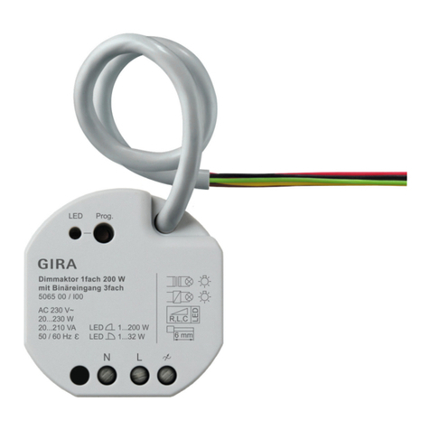
●SATION-DM0101.0210, Sation-Concealed 1 fold Dimming Actuator(200W)
Diagram Drawing

WWW.SATION.COM.CN
2
figure1.
Usage
This device can adjust the brightness of the light, which is suitable for all kinds of communication
driven lamps. According to the load type (resistance, sensibility, tolerance), the appropriate
driving type is selected.
Switch mode (direct opening/closing), relative dimming mode (based on the current brightness),
absolute dimming mode (by percentage).
Structure Specification
Refer to figure 1. Diagram Drawing, the concealed 1-fold dimmer actuator contains a
programming key, a programming indicator light, a KNX bus input, a 5 pin input terminal and a 3
pin output terminal. Five needle inputs contain two auxiliary power supply 24 v ~ 30 VDC input,
two key hand input interface (UP and DOWN) and a common ground (GND), 3 needle output
terminals contain zero line interface, firewire, and a light output interface.
Manual operation and protection operation
The single-channel device contains two manual key input, one corresponding to the light and one
corresponding to the quenching. After pressing any button, the device enters the manual mode, no
longer controlled by external command. After pressing a button more than 2s, the device sends a
100% absolute dimming command, the brightness of the lamp changes, and the time of dimming
is also affected.
The time parameter influences, release the button, send a stop command, and the dimming process
is stopped. When the system detects that the keyless action exceeds 3s, exit the manual mode, at
this point the device can accept external control commands.
The dimming channel has real-time monitoring protection operation. When the channel overpower,
or overtemperature, the channel output will be processed immediately:
(1). Overpower protection, the channel is adjusted to 75% firstly. If the power is still overpower, it
will be dimpled to 50%. If the power is still overpower, the channel will be closed until the
channel is normal.
(2). Over temperature protection, the channel is dimmed to 50% firstly. If the temperature is still
detected, the channel will be closed until the channel returns to normal.

WWW.SATION.COM.CN
3
Function
The channel has the associated parameter options that can be configured flexibly as needed.
Overview of the dimming channel function
Dimming
Function:
Load type
omic/acpacitive load / electronic transf.(trailing edge)
inductive loads / conventional transf.(leading edge)
ESL/.LED without transformer(leading edge)
ESL/LED with electronic transf.(trailing edge)
ESL without transf.(leading edge)100% start
Characteristic curve
Linear(bulb, LED, halogen lamp)
Quadrate(esl, fluorescent lamp)
Half logarithmically(optional)
Logarithmically(optional)
Time functions
Staircase lights
Switch-ono delay
Switch-off delay
Turn-on behavior
Absolute brightness level
Last value(memory-function)
Absolute values
Minimum value
Maximum value
Dimming behavior
Dimming speed
Alarm functions
Temperature
Electric load alarm
Central functions
Central switching
Central dimming
Scene functions
For every channel activatable/de activatable
Automatic functions
For every channel activatable/de activatable
Additional
Functions:
Blocking objects
2 blocking objects available
Behavior for blocking and unblocking independent
parameterizable
Behavior after power
off/after reset
No reaction
Off/on
Absolute value
Last value

WWW.SATION.COM.CN
4
Universal Interface Channel Function Overview
Eliminate the jitter time
10-120ms, optional
Long press the button
0.1-30s, optional
Enter internal pull
enable/disable
Double key dimming function
Dimming
Double key curtain function
On/Off
Double key switch function
On/Off
Single key switch function
Switch function
Toggle function
State function
Delay function
Edge sending function
Mandatory function
Sending value function
Scene function
Save function
Scene selection
Counter function
Edge checking
Step threshold setting
Switch short/long press function
Open/close/toggle
Short press/long press independent configuration
Single key dimming function
Single key dimming
Single key shutter function
Single key shutter control
Logic function:and
Switch function
Scene function
The reverse function
Logic function:or
Switch function
Scene function
The reverse function
2 Communication Object
Object Corresponding Channel
The communication which is between the devices depends on the group object. Each group is
associated with the group address.

WWW.SATION.COM.CN
5
A dimmer actuator contains three global objects and objects corresponding to each channel. When
a channel is activated, parameter configuration can be performed, and some objects are based on
parameters.
The configuration is shown in the object window. Each channel occupies 15 object positions.
Therefore, the code range of channel A is 0-14.
The three global object codes are fixed at 60,61,62.
The following figure is channel A object graph:
The global object acts on all channels, and when the channel opens the global function, it will be
controlled by the global object. This means that multiple channels open the global function. One
global object command will control multiple channels at the same time. This will help the overall
control and reduce the bus load.
The following figure is global object description:
Channel Object
If a set of channels is forbidden, the corresponding channel object is not displayed, and the
corresponding parameters are not configurable.

WWW.SATION.COM.CN
6
Dimming Channel Object
The following table is the corresponding object for a channel:
NO.
Function
Use
Length
Data Point
Type
Reading/Writing
0
Switch
Switch function
1 bit
DPT 1.001
Writing
1
Stair case light
Delay turn off
function
1 bit
DPT 1.001
Writing
2
Dim relatively
Relative dimming
4 bit
DPT 3.007
Writing
3
Dim absolutely
Absolute dimming
1 byte
DPT 5.001
Writing
4
State On/Off
Channel state
1 byte
DPT 1.001
Reading
5
State dim value
Dimming Value
1 byte
DPT 5.005
Reading
6
Block i
Blocking 1
1 bit
DPT 1.001
Writing
7
Block ii
Blocking 2
1 bit
DPT 1.001
Writing
8
Scene
Scene
1 byte
DPT 18.001
Writing
9
Electric load alarm
Overcurrent alarm
1 bit
DPT 3.007
Reading
10
Over temperature
alarm
Overtemperature
alarm
1 bit
DPT 1.001
Reading
11
Automatic 1
Automatic function 1
1 bit
DPT 1.001
Writing
12
Automatic 2
Automatic function 2
1 bit
DPT 1.001
Writing
13
Automatic 3
Automatic function 3
1 bit
DPT 1.001
Writing
14
Automatic 4
Automatic function 4
1 bit
DPT 1.001
Writing
+15
Next channel
60
Switch
Global on/off
1 bit
DPT 1.001
Writing
61
Dim absolutely
Global Dimming
1 byte
DPT 5.001
Writing
Online State Object
The online state object indicates that the device is running normally on the bus and sending state
actively.
NO.
Function
Use
Data Type
71
Online State
Send state actively on the bus
No
Output, reading

WWW.SATION.COM.CN
7
The Object of the Universal Interface Channel
Each channel has its corresponding five object numbers, which in turn are channel
A:80-84;Channel B: 85-89;Channel C: 90-94;Channel D: 95-99.
The object location will be permanently occupied and will not change due to schema changes.
The following table is the corresponding object for a channel:
NO.
Function
Use
Data Point Type
Reading/Writing
80
Switch
Edge Control
DPT 1.001
Reading
80
Send forced setting
Mandatory setting
DPT 2.001
Reading
80
Shutters down/up
Shutter control
DPT 1.008
Reading
80
Dimming on/off
Toggle dimming
DPT 1.001
Reading
80
Switch on/off
Double key control
switch
DPT 1.001
Reading
80
Reset counter
Reset counter
DPT 1.001
Writing
80
Send value
Send setting value
DPT 5.001
Reading
80
Push button short
Send short press button
DPT 1.001
Reading
81
Value for toggle
Edge control toggle
value
DPT 1.001
Writing
81
Stop/Blinds open/close
Shutter driving/Blinds
stop
DPT 1.009
Reading
81
Dimming
Dimming
DPT 3.007
Reading
82
Scene
Scene
DPT 18.001
Reading
82
Value for change of direction
Shutter move direction
DPT 1.001
Reading
82
Push button long
Send long press button
DPT 1.001
Reading
83
Counter
Counter
DPT 12.001
Reading
84
Blocking object
Blocking channel
DPT 1.001
Writing
+5
Next channel
122
LED output A
LED control
DPT 1.001
Reading
Logic Object
Each device has two logical functions, each logical function is equipped with two logical input
objects, a logic output object, and you can choose any channel to participate in the logical
operation, object Numbers from 110 to 115.
The following table is the channel A logical object:

WWW.SATION.COM.CN
8
The following table is the corresponding object for a logic function:
NO.
Function
Use
Data Point Type
Reading/Writing
110
Logic input 1A
Logic1 input A
DPT 1.001
Writing
111
Logic input 1B
Logic 1 input B
DPT 1.001
Writing
112
Logic output 1
Logic 1 output
DPT 1.001
Reading
112
Logic output 1 Scene
Logic 1 output
scene
DPT 18.001
Reading
112
Logic output 1 Value
Logic 1 output
value
DPT 5.010
Reading
113
Logic input 2A
Logic 2 input A
DPT 1.001
Writing
114
Logic input 2B
Logic 2 input B
DPT 1.001
Writing
115
Logic output 2
Logic 2 output
DPT 1.001
Reading
115
Logic output 2 Scene
Logic 2 output
scene
DPT 18.001
Reading
115
Logic output 2 Value
Logic 2 output
value
DPT 5.010
Reading
3 ETS Parameter

WWW.SATION.COM.CN
9
General Setting
Parameter Description:
Parameter Name
Range
[Default]
Remark
Startup timeout
1‐60s
[1s]
Start the timeout parameter , after the device waits for the set
time of the parameter, the application function is valid.
Send“In operation”
object
No
Send value “0” cyclic
Send value “1” cyclic
The "In operation" object is sent to the bus reporting device to
run normally, and the periodic send value can be selected "0"
or "1".
Send cycle time in s[1…65535]
1–65535s
[60]
Send the "In operation" object cycle time setting.
Debounce time
10-120ms
[30]
Signal input buffing time, optional 10ms,30ms,60ms and
120ms.
Time for keystroke long
0.1-30s
[0.8s]
Long key determination time (longer than this value is long
press button), it is necessary to determine the value when the
length of the key is differentiated.
Behavior at bus power up
No read value for toggle
Read value for toggle
When the device is reset, whether to read the toggle value or
not, 0 by default .
Channel
Each channel has the same parameter options, which can be configured differently depending on
the need, allowing the channel to perform specific functions.

WWW.SATION.COM.CN
10
Function Description
Parameter Name
Range
[默认值]
Remark
Channel A
inactive
active
Inactive indicates that the channel
is disabled, and the active
represents the enabled channel,
when the channel parameters can
be configured.
If a channel is not used, choose inactive. When the active is selected, the parameters associated
with the channel will appear for configuration, and some of the parameters will be selected.
There are more other parameters, as well as group objects, all of which are configured as needed.
Function
There are three working modes of a channel: (open/close),Dim relatively(relative dimming),Dim
absolutely(absolute dimming). When the channel is activated, all three objects will appear, which
means that the channel can switch to work mode at any time.
Switching
A channel can work in the open/close mode, which means that the channel only needs to be
opened/closed with a 0/1 signal. Unlike normal open/close operation, it can still be set Open/close
time. Object State On/Off is used for feedback channel State. When the channel is controlled by
an external single key, the object needs to connect to the external single key toggle object to
ensure the state rotation.
NO.
Name
Length
Use
0
Switch
1bit
Value 1 opens the channel, value 0 closes the channel.
4
State On/Off
1bit
Indicates the current channel status (on/off).

WWW.SATION.COM.CN
11
Dim Relatively
Relative dimming is performed continuous dimming operation on the basis of the current
brightness. The step length is 100%, which means the dimming operation is from 0% to 100% or
100% to 0%. The dimming process can be stopped at any time. The dimming speed can be set.
NO.
Name
Length
Use
2
Dim relatively
4 bit
Continuous
bright/dark.
Dim Absolutely
In contrast to the relative dimming, absolute dimming does not consider the current brightness
value, but instead adjusts the light according to a percentage, dividing the brightness into 100
equal parts and a percentage value corresponds to a brightness setting.
NO.
Name
Length
Use
3
Dim absolutely
1 bit
Set the brightness to a
specified value..
Parameter
Load Type
Choose the appropriate load type to ensure the normal operation of the equipment, trailing edge
and leading edge are very important.

WWW.SATION.COM.CN
12
Name
Option
[Default]
Remark
Load type
omic/capacitive load(trailing edge)
inductive loads/conventional transf.(leading edge)
ESL/LED without transformer(leading edge)
ESL/LED/Halogen with electronic transf.(trailing
edge)
ESL without transf. (leading edge),100%Start.
omic/capacitive load(trailing edge)
inductive loads (leading edge)
ESL/LED without
transformer(leading edge)
ESL/LED/Halogen with electronic
transf.(trailing edge)
ESL without transfer (leading
edge),100%Start.
Time Functions
The dimming process can be set in two kinds of time: one ON/OFF time, which is used for
Switching/Dim absolutely the two modes; the other one is the dimming time which is used for
relative Dim works. In addition, the channel can be configured to work in the Staircase mode,
which will automatically close after opening for a period of time.
3.4.2.1 On/Off Delay
The On/Off object is used for the delay before the channel opens/closes.
Name
Option
[Default]
Use
On/Off delay
no delay, 1s, 5s, 10s, 15s,
20s, 30s, 45s, 60s, 2min, 3min,
4min, 6min, 7min, 8min, 9min, 10min,
Set on/off delay value.

WWW.SATION.COM.CN
13
15min, 20min, 30min, 45min, 60min
The parameter On delay acts on the open operation, and Off delay acts on the closing operation.
The following diagram shows the delay:
3.4.2.2 Staircase Light
The corridor lighting mode can be configured to close the channel automatically when the delay
time is used. To use this function, the parameter activation must be selected:
When the function of the building is activated, a new parameter selection menu will appear.

WWW.SATION.COM.CN
14
名称
选项
[默认]
备注
Duration staircase
0-30000s
[90s]
The channel opens for a duration and then closes automatically.
Prewarning
active
not active
Activate the warning function. If the function is not opened, the
channel will not give warning instructions before closing.
Prewarning
Duration in[s]
0-30000s
[0s]
Early warning time is used to indicate that the channel is
closing.
Value of dimming down
1-100%
[20%]
Warning behavior can be set to a certain percentage of
brightness to indicate that the channel is closing.
Extension
active
not active
After expansion option, activate the function, when the channel
is open, open up the command, and received channel open
duration will recount, the channel can be in a state of continuous
open. If this parameter is have no choice, the channel will ignore
other open orders received during open, also is to have to wait
for channel automatically shut down after to receive external
command again.
Deactivation
active
not active
This option is used to activate external close function. When
select this function, if you receive a shutdown command, then
the channel will be shut down. Otherwise, without activating this
function, the channel will ignore all shutdown command
received. Channels can only be shut down automatically, rather
than via an external command to shut down.
When the building function is activated, a Stair case light object will appear to replace the original
Switch object:
NO.
Name
Length
Use

WWW.SATION.COM.CN
15
1
Stair case light
1 bit
Used for building function command reception.
The channel function does not respond to Dim relatively and Dim absolute commands. Therefore,
the channel does not automatically close after processing the light command received by these two
objects, but it needs to receive external commands to close.
The following figure is the schematic diagram of the corridor function, and the channel warning
brightness is set to 20%, which activates the extension and deactivation functions:
Absolute Values
The dimming area can be limited to a certain range.
3.4.3.1 Starting Behavior
This parameter is used to set the channel to open/close behavior, and it is valid for the Switch/Dim
absolutely two objects:

WWW.SATION.COM.CN
16
Name
Option
[Default]
Remark
On-value setting
Sub-function: value of start up
1-100%
[100%]
This parameter sets the brightness
value when the channel receives the
Switch object's open command.
Last light value(Memory)
This parameter indicates that the
channel receives the last brightness
value of the Switch object before the
last channel is closed.
Start up speed /Switch off speed
1s-240s
[1s]
Set the channel to open/close the
dimming time. Valid for two objects of
Switch/Dim absolutely.
Although the parameter value for startup can set the brightness value when the channel opens, the
parameter is still restricted by the dimming area, if the value is set greater than the maximum set
in the dimming area, so the brightness value set after the channel is opened is the maximum value
set by the dimming area. If the value of this parameter is less than the adjustment minimum value
set by the optical region, then the luminance value set by the channel after opening is the
minimum value of the dimming area.
For the parameter Last light value, it represents the value that is set when the channel changes
from the closing state to the open state, for example: the channel is dimmed to 60% brightness and
then turned off. When it is opened again, the channel brightness will be set to 60%, which is the
brightness value of the last time it was opened.
All of the above parameters are valid for the Switch object, but Dim absolutely objects are only
affected by the parameters Start up speed /Switch off speed. The object Dim relatively is not
affected by these parameters.
Table of contents
Other KNX Controllers manuals

KNX
KNX GIRA Standard User manual

KNX
KNX GIRA User manual

KNX
KNX Push Button RF+ User manual

KNX
KNX Berker 7531 40 18 User manual

KNX
KNX Jung 2304.16 REG HE User manual

KNX
KNX Jung 230011SU User manual

KNX
KNX Module SAS-04.16 User manual

KNX
KNX GIRA User manual

KNX
KNX Iddero Verso User manual

KNX
KNX GIRA 5065 00 User manual
Popular Controllers manuals by other brands

Pedigree Technologies
Pedigree Technologies OneView ATG installation manual

WAREMA
WAREMA KNX SA 16M230.32 SMI AP installation instructions

Airflow
Airflow MultiPlexBox ECO manual

EuroLite
EuroLite DMX LED EASY Operator Deluxe user manual

Villeroy & Boch
Villeroy & Boch L200 installation instructions

Bogobit
Bogobit Standard-Bremsmodul manual