SEC 382 User manual

SEC America Corp.
SEC
Model 382 DC-DC Converter
Owner’s Manual
Dec. 21, 2019

TABLE OF CONTENTS
page
I Introduction 1
II Installation 1
2.1 Mounting 1
2.2 Connections 1
2.3 Methods of Converter Activation 2
2.4 Power Limiting & Overload Protection 2
III Internal Adjustments 3
3.1 Voltage Adjustment 3
3.1 Current Limit Adjustment 4
IV Warranty 5
V Mechanical Drawing of Base Plate 6
VI Specifications 7
I Introduction
Model 382 is shipped in fully assembled form. After removing the unit from its packaging and ensuring
that it has suffered no damage in shipment, it is important to read this manual and follow its instructions
to ensure proper connection and mounting.
Model 382 is a high-power DC-DC down converter with a wide range (22V-60V) input capability. Its
continuous maximum output current is 30A at 13.6V. Model 382 is designed for mounting in vehicles of
all types and is capable of enduring harsh vibration and shock conditions
II Installation
2.1 Mounting
Model 382 has an overall length of 7.8 inches with mounting flanges included in this dimension. Hole
mounting centers are 7.3 x 3.75 (inches). The 382 comes with 4 rubber bumpers which may be mounted
between the baseplate and mounting surface.
2.2 Connections
Tools Required - 1 flat blade screw driver (1/4 in. wide)
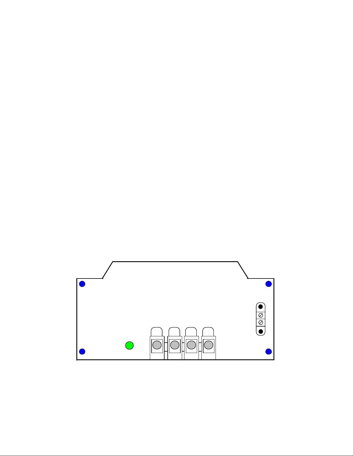
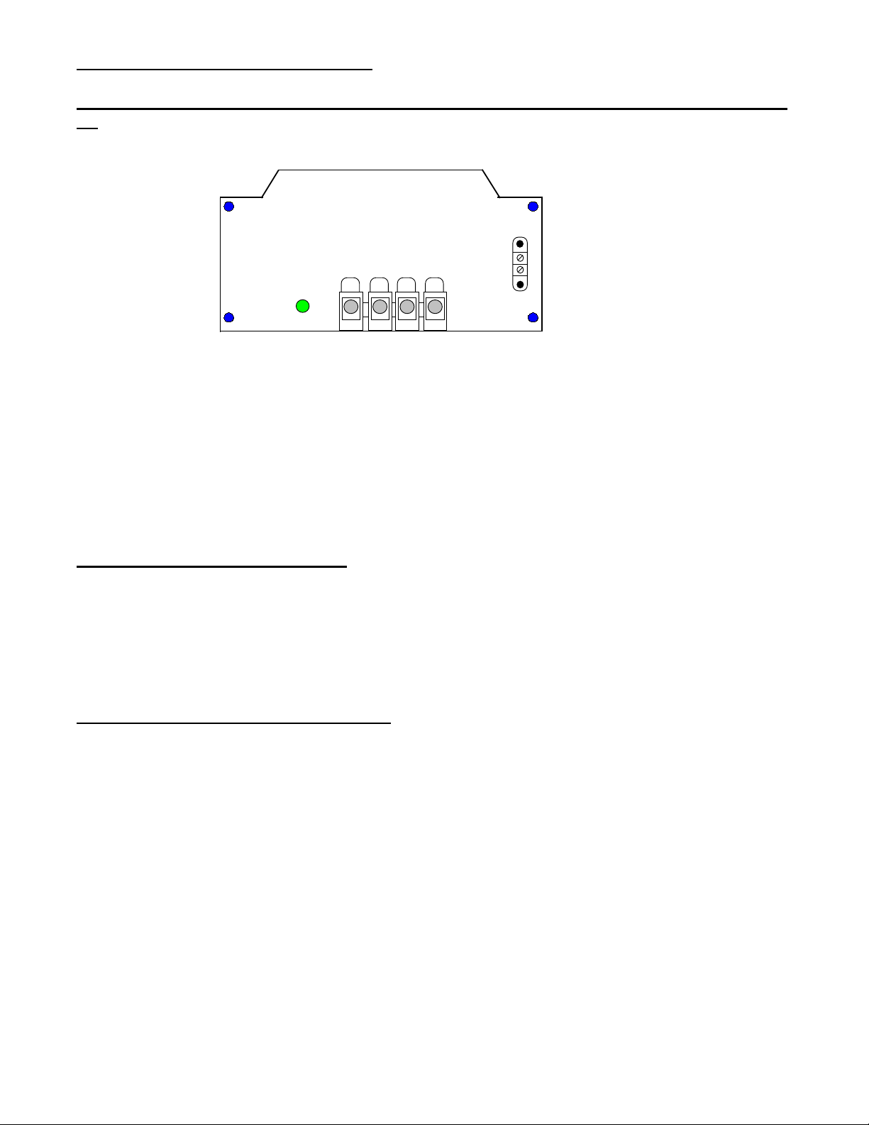
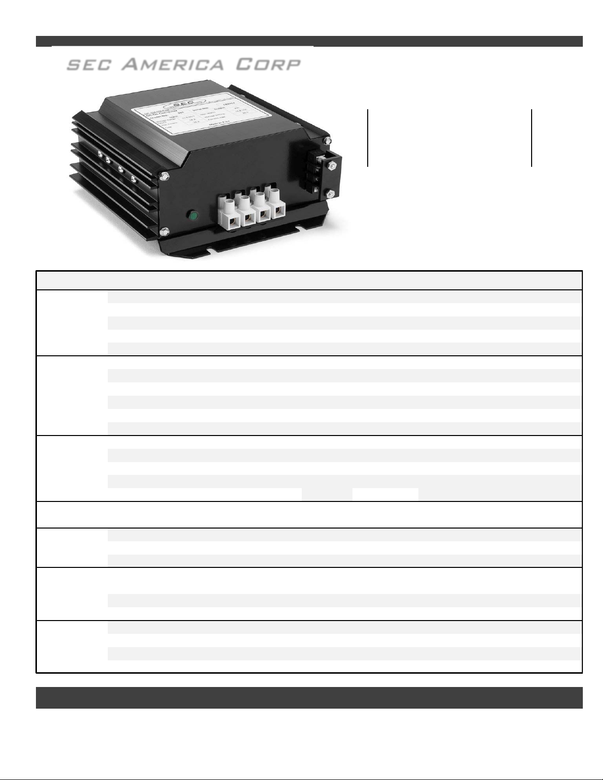
Figure 1 shows the connection panel view of the 382.
The 382 DC-DC Converter can be activated by:
1) Connecting Terminals 1 & 2 on TBA (as factory supplied)
2) By switching ON source power
OR
Activity
Light
TBA
Input
22-60 VDC
TBB
123 4
Input
Ground Output
Ground Output
13.6 VDC
1
2
Figure #1
Page 1
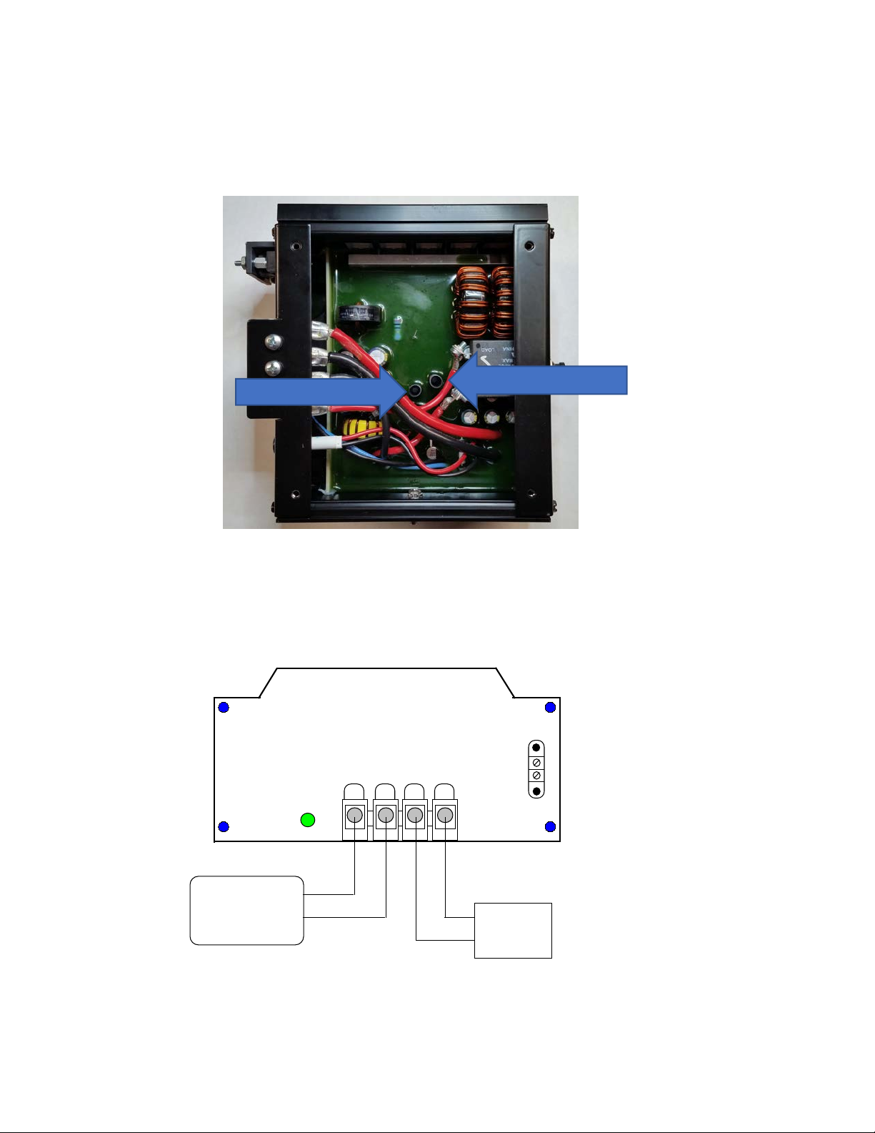
Prior to Main Input Power Connections:
Make connections A through D prior to hook up to the vehicular power source as shown in Figure
#2. This ensures that there is no sparking from the source of power and allows a reprieve in case there is
a hook up error. (User should carefully review connections as such an error would have to be detected
prior to energizing the unit).
Activity
Light
TBA
Input
22-60 VDC
TBB
1 2 34
Input
Ground Output
Ground Output
13.6 VDC
1
2
For remote Turn On Connect 1 & 2 on TBA
Figure #2
A) Connect input +(22-60)V line to position #1 of TBB.
B) Connect input ground to position #2 of TBB.
C) Connect output 13.6 V ground to position #3 of TBB.
D) Connect output +13.6V line to position #4 of TBB
Note: The two ground positions are in the center of the terminal block adjacent to each other.
Prior to energizing, installer should:
1) Ensure that hook up in steps A through D is correct.
2) Select the suitable method of converter activation.
2.3 Methods of Converter Activation
A) Connect terminal #1 to terminal #2 on terminal block TBA. The 382 is so configured
when shipped from the factory. This configuration allows for converter activation by
either turning the source power ON and OFF.
B) Terminal #1 can be connected to terminal #2 through a remote ON/OFF switch or relay
thereby activating the converter.
2.4 Power Limiting & Overload Protection
The 382 begins to electronically limit power once 450W output is exceeded.
In the event that the converter is misused e.g. its input is connected in reverse polarity, the circuit
breaker on the rear panel provides secondary protection. IT IS ADVISABLE TO TRY TO AVOID
REVERSE POLARITY AS IT MAY RESULT IN PERMANENT DAMAGE TO THE UNIT.
Page 2
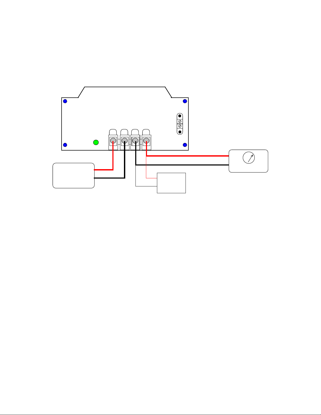
III Internal Adjustments
Varying the output voltage adjustment of the Model 382 requires the technician to have a stable DC
power supply variable from at least 20 VDC to 30 VDC.
To access the adjustment, turn the unit upside down and remove the base plate by unscrewing the 4
securing screws in its corners. (See mechanical drawing of baseplate on page 6)
Orient the converter upside down and horizontally with the connection panel to the left as shown in
figure #3.
There are two pots as shown in Figure #3. The Current limit adjust should not be touched unless the user
has a power source which can supply and a suitable load which can draw the current at which the supply
is to be limited.
3.1) Voltage Adjustment
a) Hook up the unit to be adjusted as shown in Figure #4 under no load conditions:
Activity
Light
TBA
Input
22-60 VDC
TBB
1 2 34
Input
Ground Output
Ground Output
13.6 VDC
1
2
Power Supply +24V
Ret DVM
+12 V
Ret
Figure #4
b) Make sure terminals 1 & 2 on TBA are tied together and that the power supply is turned off. Set the
Digital Volt Meter to the appropriate scale to read 12 VDC to two decimals.
Page 3
Figure #3
Current Limit Adjust
Output Voltage Adjust
c) Energize power supply and adjust its output voltage to +24 VDC. Adjust Potentiometer to the desired
setting (between 12 VDC and 14 VDC) and observe converter voltage output reading on DVM
d) Turn off power supply.
3.2) Current Limit Adjustment
a) Hook up the unit to be adjusted as shown in Figure #5. Apply a load set to the desired current draw at
the limit point:
Activity
Light
TBA
Input
22-60 VDC
TBB
1 2 34
Input
Ground Output
Ground Output
13.6 VDC
1
2
Power Supply +24V
Ret DVM
+12 V
Ret
Figure #5
Load
A
b) Turn the current limit pot completely clockwise. Turn on the power supply and note that the load is
drawing current and note the voltage on the DVM.
c) Turn C limit pot slowly counter clockwise while observing the DVM reading. When the voltage drops
by 100 mV while the pot is being turned, that designates that the current limit point has been reached.
d) Adjustment is complete. Turn off the power supply.
Page 4

IV Warranty and Repair
Should your investigations indicate that your new Model 382 is defective or damaged and your unit is
still under warranty then contact SEC America, LLC at 802-865-8388 and obtain return merchandise
authorization for credit or exchange.
If the warranty period has expired or if the warranty has been violated due to operator error or misuse,
call:
SEC America Corp., Repair Department, at 802-865-8388 or fax SEC America Corp. at 802-865-8389 to
receive authorization for shipment back to factory for a survey and possible repair.
Warranty
The Model 382 has a 2 year warranty covering parts and labor. The warranty is found below:
We warrant each instrument, sold by us, or our authorized agents, to be
free from defects in material and workmanship and that it will perform
within applicable specifications for a period of two years after original
shipment. Our obligation under this guarantee is limited to repairing or
replacing any instrument or any part thereof,except fuses and pilot lights,
which shall within one year after delivery to the original purchaser, be
returned to us with transportation charges prepaid, prove after our exa-
mination to be thus defective.
LIMITED WARRANTY
The above limited warranties take the place of all other warranties,
expressed or implied, and correction of such defects by replacement or
repair shall constitute a fulfillment of all obligations under the terms of the
warranties. The warranties do not cover any unit that has been damaged
either in transit or by misuse, accident or negligence. No warranty or re-
presentation by anyone other than this Company shall be binding on us.
To return a unit send only to the following address:
SEC America Corp.
78 Ethan Allen Drive
S. Burlington, VT 05403
PLEASE RETAIN YOUR ORIGINAL BILL OF SALE. IT MUST
BE SUBMITTED WHEN MAKING ANY WARRANTY CLAIM
Page 5
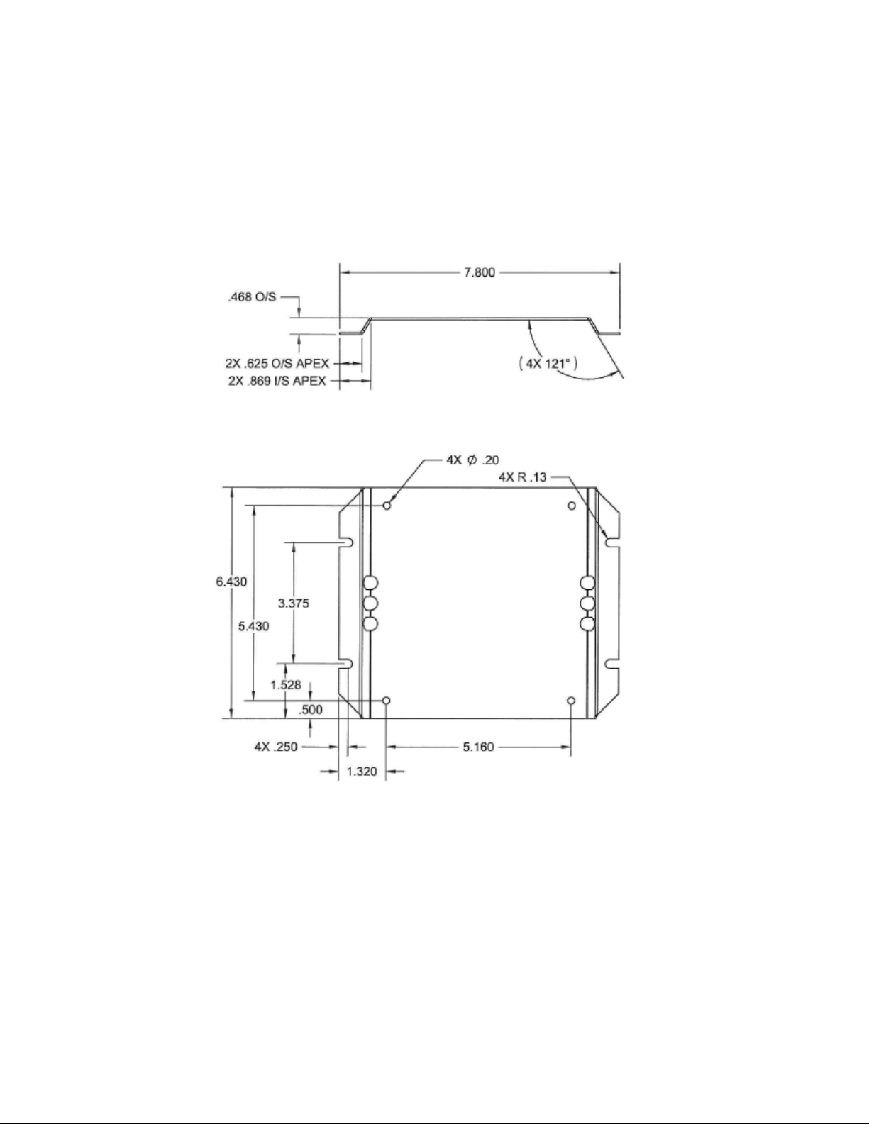
V Base Plate Mechanical Drawing
Page 6
Design Features
- Low Input Voltage Cutout
- Compact design
- Convection Cooled
- High Efficiency- 96% minimum
- Common Input/Output Negative Terminal
- Soft start technology
SPECIFICATIONS
NOMINAL INPUT VOLTAGE 48 VDC
INPUT VOLTAGE RANGE 22 to 60 (+/- 0.5) VDC
INPUT CURRENT AT MAX CONTINUOUS POWER 16.5 A / 8.2A @ 24 / 48 V
in
MAX. INPUT CURRENT AT NO LOAD 0.30 A when converter is in "ON" state
MIN. INPUT CURRENT AT NO LOAD <0.002 A when converter is in "OFF" state
OUTPUT VOLTAGE
13.6 - 13.8 VDC (factory set, internally adjustable)
OUTPUT VOLTAGE REGULATION < 40 mV, NL to Full Load
RATED MAX OUTPUT CURRENT 30 A
OUTPUT POWER, CONTINUOUS (RESISTIVE LOAD) 400 W
OUTPUT RIPPLE & NOISE <50 mV RMS
EFFICIENCY AT MAX CURRENT (30A) 96% minimum
LOW INPUT VOLTAGE SHUTDOWN 19.0 - 21.0 VDC
HIGH INPUT VOLTAGE SHUTDOWN > 64.0 VDC
OVERLOAD CURRENT LIMITING Electronic knee type at power limit
OVER TEMPERATURE SHUTDOWN Yes (Auto reset)
INPUT REVERSE POLARITY PROTECTION Resettable Integral Circuit Breaker
High pass filters allow RF signals in the PLC4 spectrum to pass between
input and output terminals with attenuation <3dB
INPUT CONNECTION WECO Screw Terminal Block
OUTPUT CONNECTION WECO Screw Terminal Block
REMOTE CONTROL PORT Yes
AMBIENT AIR OPERATING TEMPERATURE RANGE -30C to +50C no derating
Derate 15% per 10C above 50C to a maximum of 60C
OPERATING HUMIDITY <95%, non condensing
ALTITUDE 6000 meters
DIMENSIONS, INCHES (L x W x H) 7.8 x 6.9 x 3.6
MOUNTING CENTERS, INCHES (L x W x H) 7.30 x 3.38
VIBRATION & SHOCK RESISTANT Internally Encapsulated
WEIGHT (LB/KG) 6.0 / 2.75
NOTE: Specifications are subject to change without notice.
Page 7
ENVIRONMENT
MECHANICAL
PROTECTIONS
RF
TRANSPARENCY
MODEL 382
Wide Input Range Down Converter
22 Vdc-60 Vdc to 13.6 Vdc
CONNECTIONS
OUTPUT
SEC America Corp.
SE
C
America Cor
p

SEC America Corp.
SEC
Model 382 DC-DC Converter
Owner’s Manual
Table of contents
Other SEC Media Converter manuals


