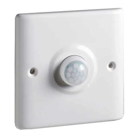
CHDD KG316T User manual

Firstly please press clock , then press cancel & reset consistently for
4 times, there will appear the symbol of " " Now, When the keyboard is
in the state of Off , Micro-switch would not accept t he u sual c ommand.
Next press cancel & reset consistently f or 4 t imes, th e" " w ill di sappear.
Then the keyboard is On , so it could accept any command!
1.Firstly, please make s ure t hat t he k eyboard in th e s tate o f o n ,a nd th en
press Clock to check whether the time on the screen correspond with
the present time or not. If not, please press the week , retime , minute
to adjust the time to the current.
2.Press Timer, 1ON will appear in the left down on the left down of the
screen (it means the f irst ON time). Next, press minute, hour to input
the required time of ON .
3.Now press Timer , 1OFF appear in the left down of the LCD screen.
Next, press week hour minute to input the required time of ON
4.Again press Timer , 2ON & 2OFF ,8ON,8OFF will appear on the left
down . After reference to the steps 2&3, the each time of On & Off
could be set.
5.it must press cancel/reset if the 8 groups of s witches a re n ot r equired
everyday. So the rest of groups of time disappear, then the design of
will be in the screen.
6.after timer setting, pleas press , the screen w ill s how th e cu rrent tim e.
unday.
usage introduction
about the keyboard
Time Setting
Example 1: a kind of electronics is required to connect at 19:00
everyday, disconnect next day at 08:00
A.according to the steps 1.2, the screen is as the diagram 1a
B.according to the steps 3, the screen is as the diagram 1b
ON
C.according to the steps 5, the screen is as the diagram 1b, 2
OF F ON OF F
& 2 ,8 ,8 will appear in the screen as --:-- .
D.Again press timer to check whether each group of On & OFF
time is same as required. If not, please do as from AC
E.According to steps 6,7, take" "to automatic position.
7. Press Manual/auto to move the" "in the down screen to auto .
Now timer switch can automati c conne ct an d bre ak t he circ uit
according the time setting. If it temporary needs to switch on or off
the circuit during work,pleas e pres s manual/a uto to ma ke" "
remove correspondingly to the place of on/off .
8.Press timer , next press week . It could be set in eight state of on
& off . E.g. the s ame o r d ifferent f or e veryday, th e sa me fro m M onday
to Friday; the same from Monday to Saturday, the same Saturday
and Sunday.
EXAMPLE 2: one electronics is required to connect at 9:30am
from Monday to Friday,, disconnect at 16:30.
Follow the steps AE to make the screen on as diagram 2a,2b.
Mo TU WE TH FR SA Su
1ON 19 : 00
Diagram 1a
Mo TU WE TH FR SA Su
1OFF
8 : 00
Diagram 1b
Mo TU WE TH FR
1ON 9 : 30
Diagram 2a
Mo TU WE TH FR
116 : 30
Diagram 2b
KG316T Micro-computer time switch
Theguideforusage
Please read this guide before using, ensure to use this product correctly!
After reading, please keep this guide.
Functions & Applications
Micro-computer time control s witch c ould c onnect a nd b reak th e po wer
of all kinds of electric appliance. The control items includes road lights,
neon light and advertisement light, production equipment and radio &
TV setting which is required to open & stop.
Tech date
Standard operating power
220V/50HZ
Applicable power range160-240V
Switch volume resistive load 25A,
inductive load 20A
Power consumption
The time control range 1 min168
hours, weight 430G
8 groups of switch time, manual/
automatic operation
Counter time mistakes
< 0.5 second/day
environment temprature
-25~60
relative humidity<95%
120X74X58mm
Outline dimension
display screen show symbol explanation
Week
ON
time group No 1ON
Mo TU WE TH FR SA Su
9 : 30
hour : minute
ON OFF
OR AUTOMARK
KG316T
Micr o - computer time switch
OFF

If the switch fails to connect or break the circuit at the programmed
time it is likely that the weekday is not correctly set. Check o r r eadjust
it according the instructions in time setting .
If it is sure that connect and break time are correctly set and the
switch connect or break the circuit in the incorrect time,it is likely that
the other time groups are deleted . Delet e them accordin g t o tim e
setting . (Note: --:-- signifies that the time groups are deleted ,while
00:00 does not.
If the switch still could not run smoothly after checking the above two
cases, it is likely that manual/automatic has been touched manually.
Check the code of on, auto, off and adjust it in the state of present
time, and then adjust it back to automatic position.
In case of the switch still could not function, open the safeguard cover
( terminal cover) to check if the fuse tube is all right. Replace it a new
one(0.1A~0,15A) if it is broken.
If the trouble is still not settled yet, contact the company or the native
distribution office.
Trouble shooting
The switch is not to be used in the equipments that will cause
life damage or great social reaction if the device fails to function
(e.g. medical apparatus, large-scale equipment, etc.)
Enough residual values on its performance should be provided
if the switch is to be used in equipment that will cause property
damage in case of the device being out of action (e.g. large-
scale heating machine, freezer, etc)and safeguards as double
circuit, etc should also be adopted.
The user should repair, dissect, or transform the switch, or else
electric shot, fire, or faultmay occur. Such operations should be
submitted to the distribution office or unit that in charge of
engineering.
Don't touch the terminals when power is on.
The ambient environment of the switch should be dampness,
corrosion free, without long-duration sun light, or in the gas that
has high metal content.
Keep it from oil and water.
1. Direct control
This pattern is adopted when the appliance to be controlled is
supplied in single phase model and its power consumption is less
than the rated value of the switch, (resistive load 25A, sensitive
load20A). Its wiring method see Diagram 1.
2. Single-phase capacity enlarging
The pattern is adopted when the controlled appliance is supplied in
single phase model while its power consumption is above the rated
value of the switch (resistive load25A, sensitive load20A). In this
Attentions
Wiring pattern case a AC contactor that is larger than the appliance in its power
consumption should be used to enlarge the capacity. Wiring method
see Diagram 2.
3. Three-phase type
The pattern is adopted when the controlled appliance is supplied in
three phase model and a three-phase AC contactor is needed.
The wiring pattern of the contactor (the voltage of its coil AC220V,
50Hz), see Diagram 3.
The wiring pattern of the contactor (the voltage of its coil AC380V,
50Hz), see Diagram 4.
installation
dimension
74mm
30.2mm30.2mm
106.5mm
4
120mm
KG316T
T T
input output
power
load
CJ
KG316T
T T
input output
power
load
KG316T
T T
input output
load
CJ
A
B
C
N
KG316T
T T
input output
load
CJ
A
B
C
N
Diagram 1 Diagram 2
Diagram 3 Diagram 4
Table of contents
Popular Timer manuals by other brands
Stanley
Stanley TIMERMAX DIGISLIM TM-262 quick start guide
Tamarack Technologies
Tamarack Technologies Airetrak 1A ADVANTAGE Product guide
Kessler-Ellis Products
Kessler-Ellis Products DT20 Installation and operating manual

BN Thermic
BN Thermic TS-7 instructions
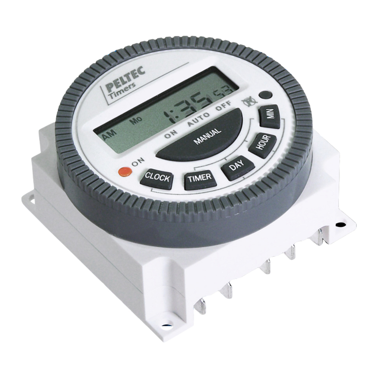
Peltec
Peltec 600 Series quick start guide

sisel
sisel ENDA ETM742 quick start guide
