Chengdu Hangfa Hydraulic Engineering Co., Ltd Compass Q2 User manual

Compass Q2
Four-wheel Omni-directionalRobotPlatform
User Manual V1.2
Chengdu HangfaHydraulicEngineering Co., Ltd
RobotDivision
Feb3rd,2017

1
Safety Warnings
Pleasedonot switch onpower fortherobot beforeyoureadand fully understand thisManual.
Pleasedonot plugordismountany partof therobot whentherobot ispoweredon.
Pleaseswitch themain power off if anyemergency happens.
Originalpoweradaptorshall beusedforcharge.
Therobot platformdoesnotfireprooforwaterproof,thereforepleasekeeprobot platformaway
from fireorwaterasfaraspossible.
Pleasekeepasafedistancefromrobot platform,forerrorsmightoccurwhetherontheprogram
itself orduringmanualoperation.
CopyrightStatement
HangfaCompanyownstheintellectualpropertyrights ofthisManual,and hardware&software
involved. Anyoneoranypartyshall not copy,plagiarize,discloseorreleaserelevantcontents in
any formwithoutwrittenauthorization of HangfaCompany.

2
CATALOGUE
1Description................................................................................................................................3
2Features....................................................................................................................................3
3GettoknowyourDiscovery Q2................................................................................................4
3.1 Exteriorstructure..........................................................................................................4
3.2 Interiorstructure...........................................................................................................5
4LetyourCompass Q2robot platformmove.............................................................................6
4.1 PositionParallelMovementDEMO...............................................................................7
4.2 Self-movementin PlaceDEMO.....................................................................................7
5SystemBrief Introduction.........................................................................................................8
5.1 TypicalResearch and Application Area.........................................................................8
5.2 Specification Parameters...............................................................................................8
6Mechanicalsystems..................................................................................................................9
6.1 Dimensions....................................................................................................................9
6.2 Main structure ..............................................................................................................9
6.3 Motor............................................................................................................................9
6.4 Omni wheel.................................................................................................................11
6.5 Rocker suspension.......................................................................................................11
6.6 Usersextension platform............................................................................................11
6.7 Thethreadhole...........................................................................................................11
7Electric system........................................................................................................................12
7.1 Electricalprincipledrawing.........................................................................................12
7.2 IMDR4Fourshaftdriver..............................................................................................13
7.2.1 TheModuleoverview.....................................................................................13
7.2.2 Interfacedescription.......................................................................................13
7.3 IFB1205powerand busportmodule .........................................................................16
7.3.1 Modulesummary............................................................................................16
7.3.2 Portdescription...............................................................................................16
7.4 RHF407DevelopmentBoard......................................................................................19
8User Extend ..........................................................................................................................19
8.1 BusExtend...................................................................................................................19
8.2 RHF407Extend............................................................................................................19
8.3 DesignYourOwnMain Control Unit...........................................................................20
8.4 AccessoriesCanBeChoose.........................................................................................21
9PackingList..............................................................................................................................21
10TechnicalSupportand Quality Guarantee......................................................................21

3
1Description
Aseconomicalsmall robot platform,theCompass seriesareaimedatofferingacomplete,
multi-interfacedand highlyreliablemovingrobot systematthebestcost-performance.Compass
Q2issuch aplatformwithfourQMA-10Mecanum wheelswhich are madebyHangfaitself.
Comparedtothetraditionalones,thewheelsareabletomove laterally,rotate,orrotatewhen
move laterally.Therobot platformchassisismadebymold. Compass Q2isdrivenby4high
power coreless servomotorswith4-axisservodriver,and supports CAN busand RS232 serial
ports.SDKisprovidedtotheuserswithcompletecommunication protocol and thesamplesand
demonstration programssourcecodebasedontheSTM32F407,so thattheuserscould getit
startedassoonaspossible.
2Features
360degree free movement
With 4Mecanum wheels,therobot platformisabletomovein all directionshorizontally,and
rotatein thesametime.
Suspension system
Rockersuspension structureenablesthe4wheelstotouch theground and bedrivenevenly.
Thissuspension systemcanhelp reducingvibration whenpassingtheroughground.
Whollycasted chassis
Thisrobot chassisismadebymold withstrongstructure.Ourprocessingcenter keeps
thehighprecisefour-wheelrelativeposition Thischassisismuch stronger thanthewelded
chassiswhich iswithbigerrorand lowprecision.
PreciseMecanumwheel
Theclassic seriesQMA-10Mecanum wheelismadebyHangfawithindustrialgrade
quality.Each wheelroller iswithtwobearingwhich movessmoothly and steadily.
Coreless DC servomotor
The4coreless DC servomotorsrealizethehighpower density,hightorqueandquick
speedresponse.Themotoriswithpreciseplantgearboxand 500RMPencoder.
4-axis servodriver
Such driverenablesthemotortoperformagoodcharacteristic curve.Theusercould
control themotorspeedquickandaccurately,not affectedbythechangesin theloadingand
ground, so thattherobot performs accurately and reliably.

4
DEMOdevelopmentboard
With STM32F407asthecore,theRHF407developmentboardofferstheopensourceC#
programming languageSDK,toaid theuserstooperateontherobot.Highcomputing
performanceand multipleports enabletheusertocarryonitdifferentapplication and
development.
3Gettoknow yourDiscovery Q2
3.1 Exterior structure
1、wire hole
Wirefrom insideof therobot tooutside.
2、Bigcoverplate
3、Wireless receiver module
4、RHF407developmentboard
STM32F407 asthecoreofthedevelopmentboard,itofferstheusersdemonstration
programand application sourcecode.Forthedetails,pleasechecktheRHF407User
Manual.
5、Small cover plate
6、rechargersocket
Forrechargingthe robot;therechargingstateisindependentof powerswitch.
7、powerlight
Thatthelightison/off indicatestherobot ison/off.
8、powerfuse
Thefusewill blow outforprotection, in thecaseof shortcircuitorfalseoperation.
9、powerfuse

5
Thefusewill blow outforprotection, in thecaseof shortcircuitorfalseoperation.
10、Chassisbody
11、QMA-10 Mecanum wheel
3.2 Interior structure
1、PlantGearbox
2、Motor
3、Encoder
4、Driver
5、Lithium Battery
6、Power sourceandbusports modular

6
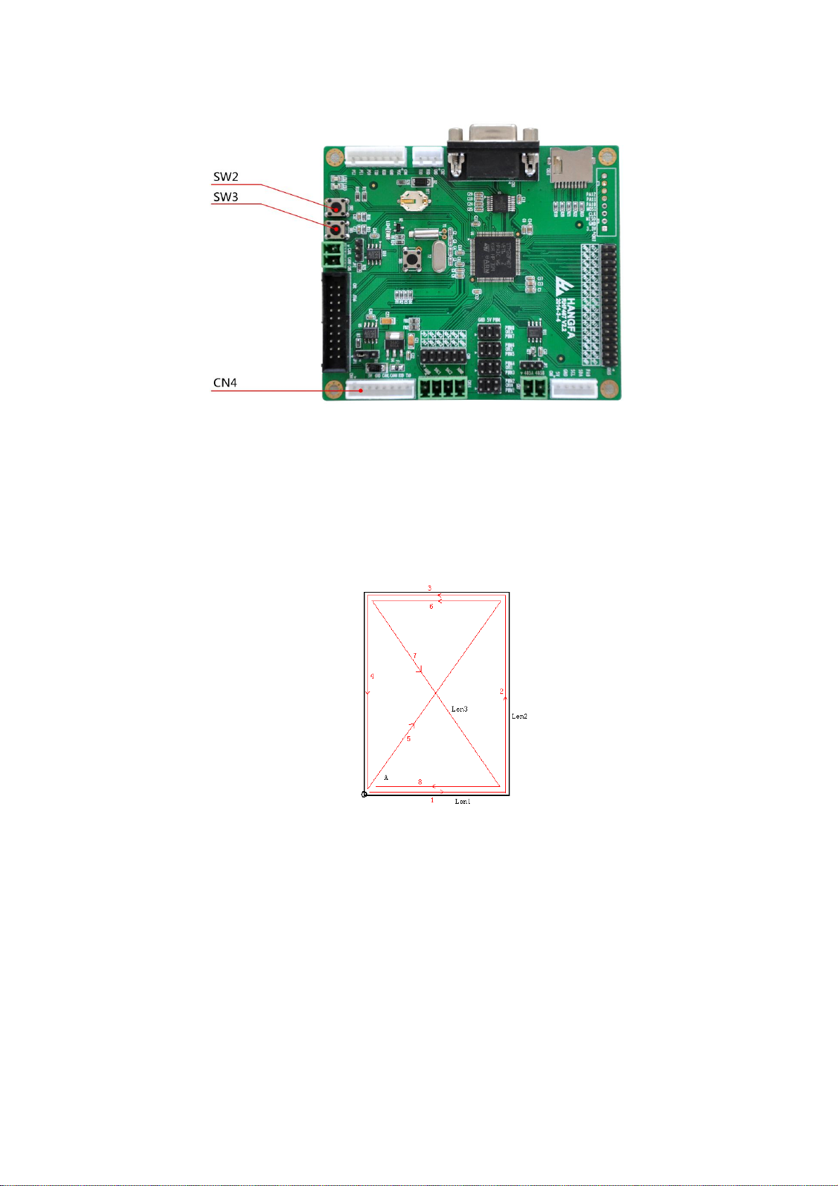
4LetyourCompass Q2 robotplatformmove.
ByRHF407 developmentboard,discoveryQ2pre-buildstwodemonstration programs,
which demonstratetherobotparallelmovementfunction and self-movementfunction The
user canpushSW2andSW3buttonsonthedevelopmentboardtoachieveaction1and
action 2.Itisnecessary toinstall theRHF407develop boardontotherobot, connecttheCN4
porttoany 8pin plugof theIFB1205BIMby incidentalcable, and switch iton
Step1:Disassemblethetoppaneltocheckeach component.
Step2:Connectthebattery plugtotheJ6portof IFB1205board
Step3:Assemblethefuseand turnonthepowersourceswitch.
thepowerindicatorlightshould belightedup,Ifyoupushtherobot platformslightly,you
would feeltheself-lock dragforthtothemotorproducedby servodriver.
Step4:Connectonesideofthesinglegraycablebusin thecasetoany8PINplugof
IFB1205board,and theothersidetotheRHF407boardfrom thetoppanelthread
hole.
Step5:FixtheRHF407 boardonthesetpositionandfixthetoppanelontherobot.Then
connectthegraycablesidewhich isoutofthethreadholetotheCN4portof
RHF407board.
Step6:Positiontherobot ontothevacantflatsurfaceand turnonthepowerswitch. After
that,theLED1ontheRHF407boardwill twinkle.ThenseparatelyclicktheSW2
and SW3buttonontheRHF407boardtomaketwodemonstration movement
programs operate.
IFB1205PowerSourceandBIM
7
RHF407DevelopmentBoard
4.1 Position Parallel Movement DEMO
Click theRHF407SW2button,therobot will makea parallelmovementaccordingto theroute
of thebelowrectangle.Therectanglewidthis0.8m,lengthis1.6m.
4.2 Self-movement in Place DEMO
Click theRHF407SW3button,therobot will makeself-movementin placefor20 seconds.

8
5System Brief Introduction
5.1 Typical Research and Application Area
Research onpatternrecognition technology Electronic EngineeringExperiment
Research onPathPlanningTechnology Mechanicalengineeringexperiment
Research onautomatic drivingtechnology Embeddedsystemdevelopmentand experiment
Research onsensortechnology Research onimageprocessingtechnology
Research onartificialintelligencetechnology Research onmultirobot cooperation technology
Handlingand storageapplications Maprenderingapplication
Monitoringand investigation application Application of flexiblemanufacturingsystem
Robot competition
5.2 Specification Parameters
Table1.Compass Q2SpecificationParameters
Body structure: Aluminum Alloy MoldingWholeShape
Dimension: 450 330 115mm
Drivenwheel: QMA-10 Omni wheel
Diameterof drivingwheel: 101.6mm
Drivenmode: four-wheelindependentdrive
Suspend kind rockerarmsuspension
Minimum spacebetweenrobot toground: 22.5mm
Ratedloadcapacity: 20kg
Maximum translationalspeed: 0.75m/s
Maximum rotation speed: 215°/s
Adaptive ground indoor, bituminousground ,concreteground
withlittledepression
Typicalduration time 10h(loadcapacity10KG,movingspeed
Standby time >30h
Chargingtime4h
Supportelectricity output 5V@2.5A
12V@2.5A
(22~29.2V)@>5A
Battery output24V
Battery capacity7.8Ah
Battery lithium-ion battery
Battery fastchange: Support
Chargerinputvoltage AC100V~240V
Interface directplug-in
Chargingcurrent: 3A
Thedefaultspecification of Thepowerof 5×20/10A

9
insurancetube:
DEMO developmentboardmodel STM32F407
6Mechanical systems
6.1 Dimensions
6.2 Main structure
Compass Q2ismadeby aluminum alloy castingprocess, thebottom and theinsidewitha
protrudingribs, supportear,which will reducetheconnection of platform, so itwill makefull
useof thematerialproperties.Themain structureisone-timeproducingwhich makesitwith
highstrengthand highrigidity;itavoidstheshortcomings such aspoorprecision, poor
integration errorand poorrigidity of theassembly of thesteelplate.
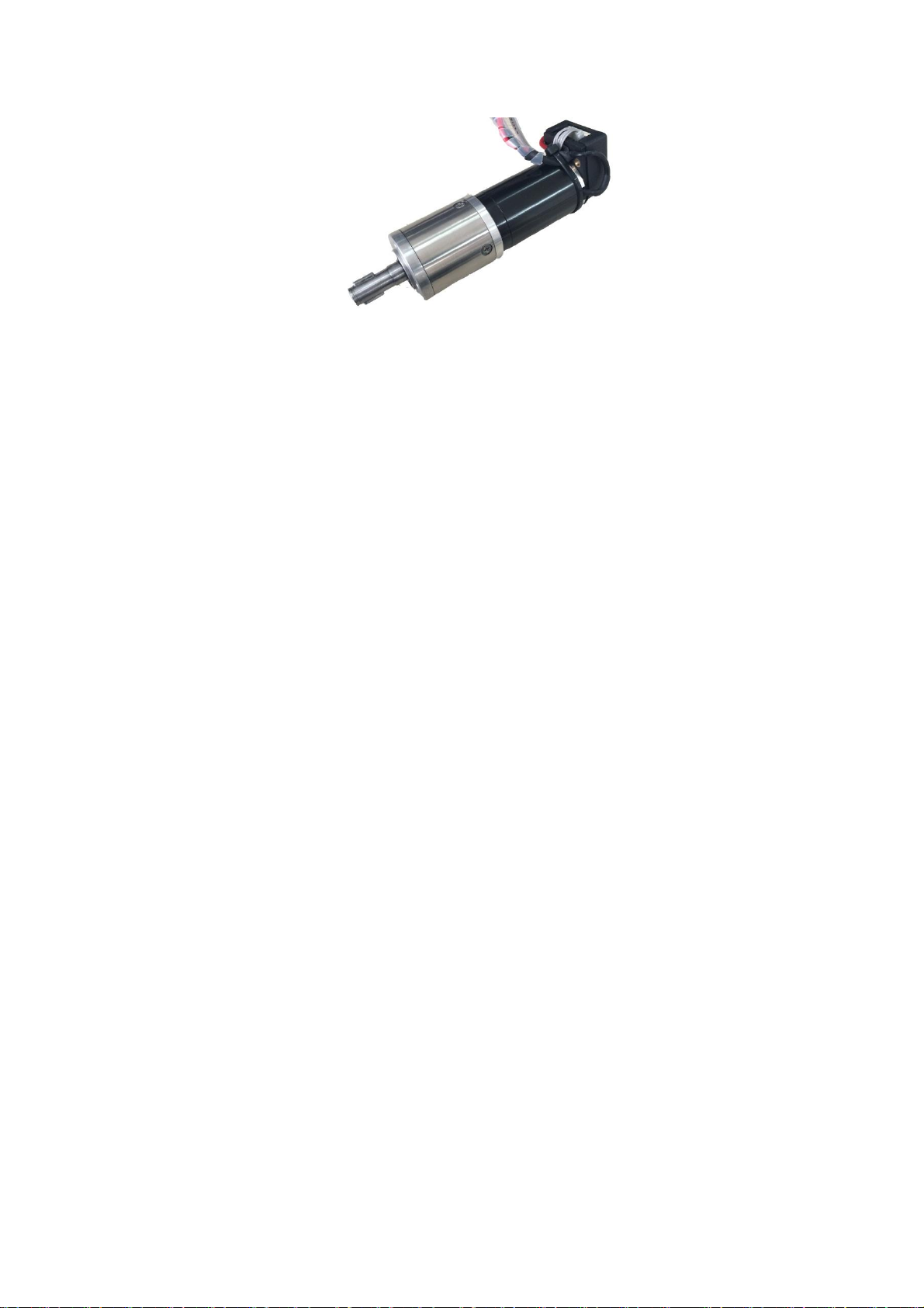
6.3 Motor
Compass Q2usesHFmotor-3230motor.Testparameters:
Ratedvoltage:24V
Ratedcurrent: 1.45A
Ratedoutputpower: 31W
Noloadrotatingspeed:6450rpm
Ratedrotatingspeed:5230rpm
Reduction ratio:24:1
Encoder :500line/rev,A、Bphaseoutput
Encoder ratedvoltage:5V
10
11
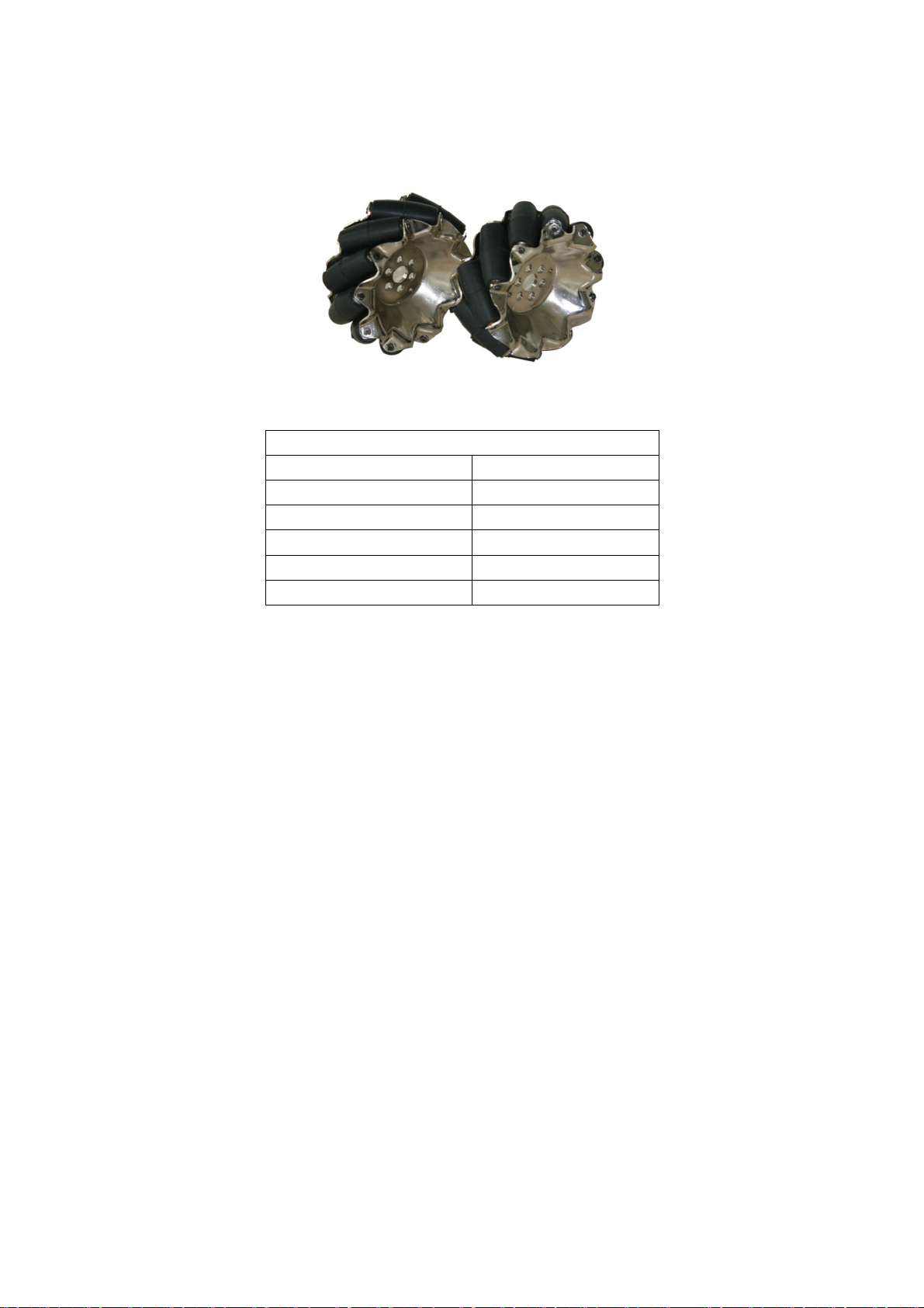
6.4
Omni wheel
Table2Themainparameter ofQMA-10 Omniwheel
Hangfa IndustrialQMA-10Omni wheel
Diameter101.6mm
wide45.7mm
Roller number10
Bearingnumber20
Hub materials steel
Loadcapacity 30kg
6.5
Rocker suspension
Rockersuspension structureenablesthe4wheelstotouch theground andbedrivenevenly.This
suspension systemcanhelp reducingvibration whenpassingtheroughground. ThePolyurethane
shockabsorberhelpsreducingvibration whentheplatformismoving.In thisway,theworking
environmentof theaddedequipmentwould beimproved.
6.6
Users extension platform
Theplateontherobot ismadeofonebigboardandonesmall board. There ispowersource
switch onthesmall board, pleasedonot disassembleit.Thebigboardisforuser toextend. Users
canadd other equipmentandstructuretothisboardasrequired.
6.7
The thread hole
Thereare manythreadholesontheplatewithrubberring.Theholeisforconnection ofthread
outsideoftherobot and insideoftherobot.Thehalf-openedthreadringonlyrequiresthe
threadtobepushedtothethreadring, noneedtocross theplate.
12
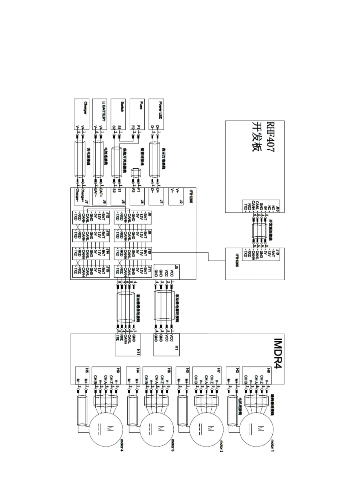
7Electricsystem
7.1
Electrical principle drawing

13
7.2 IMDR4 Four shaft driver
7.2.1 TheModuleoverview
Thismoduleisusedtodrivethefourdc servomotorsand provideaccuratespeedclosed-loop
control.Italso integratesmotioncontrol algorithm ofthefouromnidirectionalwheels.Userscan
realizetheoverall chassismotioncontrol ordirectlyforeach motormotion control throughthe
communicationsvia CAN busand RS232interface.
Formoredetails,pleasecheck IMDR4fourshaftdriverCancommunication protocol, and MDR4
fourshaftdriveUART communication protocol .
7.2.2 Interfacedescription
7.2.2.1 Interface summary
Table3 IMDR4 Interfacesummary
Interface
serial
number
Description Remark
H1 Power input
H2 Motor1powerinterface
H3 Motor2powerinterface
H4 Motor3powerinterface
H5 Motor4powerinterface
H6 Motor1encoder interface
H7 Motor2encoder interface
H8 Motor3encoder interface
H9 Motor4encoder interface
H11 RS232、CAN businterface
JP2 CAN bus120Ωresistancejump line
14
7.2.2.2 H1,Main power input port.
Table4 IMDR4 mainpower inputport
PinNo.Description note
1 GND
2 GND
3 VCC
4 VCC
7.2.2.3 H2、H3、H4、H5, Motor 1、Motor 2、Motor 3、Motor 4power input
Table5 IMDR4 motor1,2,3,4 Power interface
PinNo. Description note
1 M+,Motor+
2 M-,Motor+
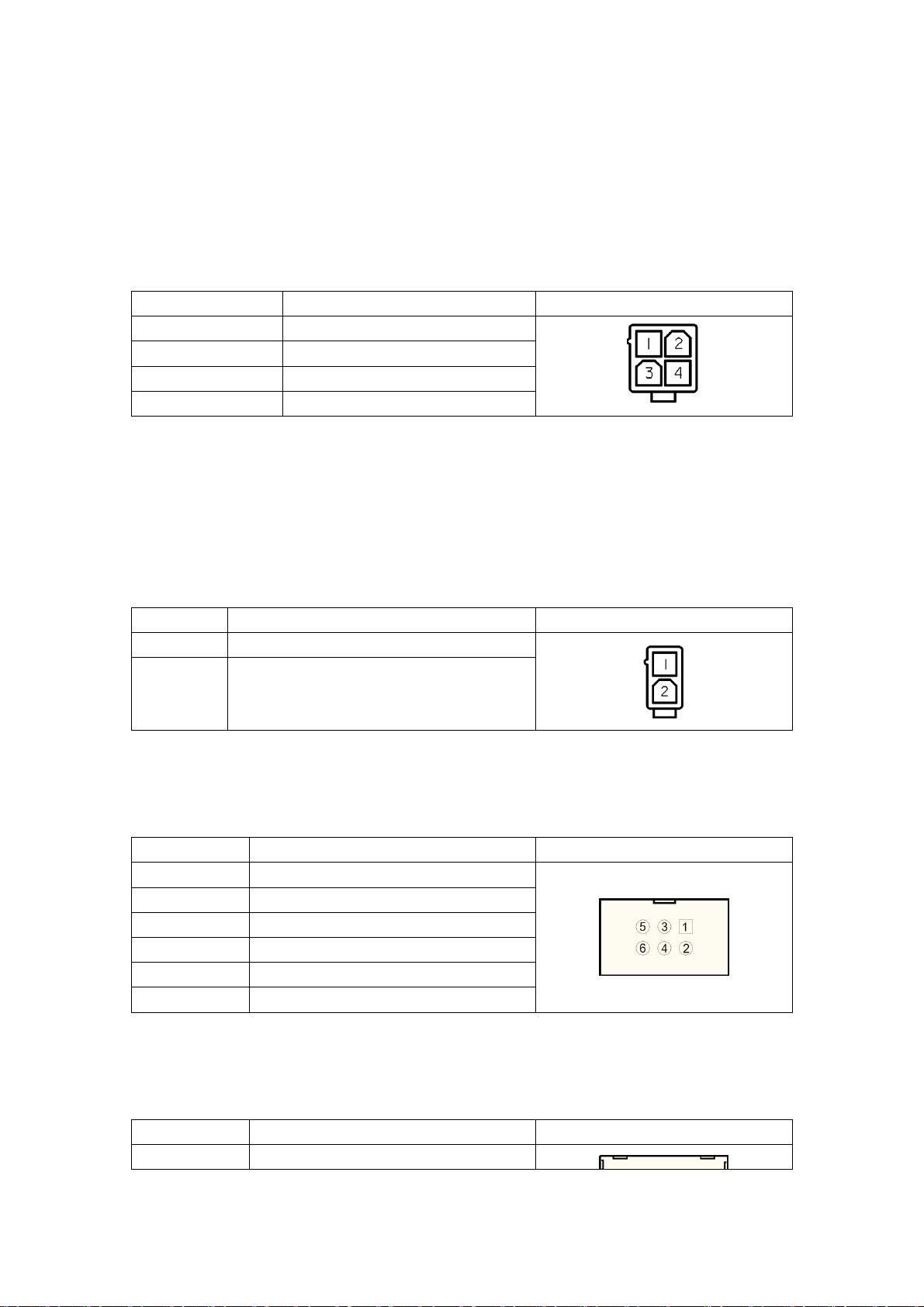
7.2.2.4 H6、H7、H8、H9,Motor 1、Motor2、Motor3 、Motor4 encoderinterface
Table6 IMDR4 motor1、2、3、4 encoder port
PINnumber
description remark
1 NC
2 CHB
3 5V
4 CHA
5 NC
6 GND
7.2.2.5 H11, communication port
Table7IMDR4 motor1、2、3、4 communicationport
PINnumber
description remark
1 GND

15
2 CANL
3 CANH
4 RXD
5 TXD
16
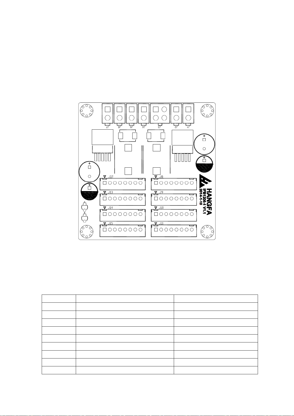
7.3 IFB1205power and busport module
7.3.1 Modulesummary
Thismoduleisusedforpower supplyand line-concentratingofcomponentand
equipment.Supplybatterypowerandtwowaystep-downpowerstousers’equipment.
Themodule output eightwaypowerportand busport,theusers’canuseelectricityand
communication network easily fortheequipmentthroughtheseport.
7.3.2 Port description
7.3.2.1 Port summary
Table8 IFB1205 port summary
Portnumber
Description Remark
J1 Indicatorlightaccess port
J2 user chargeport
J3 IFB1205 poweroutputport UsedforconnectIMDR4drive
J4 Fuseaccess port
J5 powermain switch port
J6 battery access port
J7 Chargeraccess port
J8 Standardpower andbusport J8、J9port’s5、6pin cross connect
J9 Standardpower andbusport
17
J10 Standardpower andbusport J10、J11port’s5、6pin crossconnect
J11 Standardpower andbusport
J12 Standardpower andbusport J12、J13port’s5、6pin crossconnect
J13 Standardpower andbusport
J14 Standardpower andbusport J14、J15port’s5、6pin crossconnect
J15 Standardpower andbusport
7.3.2.2 J1, Indicatorlight access port
Table9IFB1205 Indicatorlight access port
PINnumber
Description Remark
1 D+
2 GND
7.3.2.3 J2, userchargeport
Table10IFB1205 user charge port
PINnumber
Description Remark
1 24V/BAT,voltagechangedalong
with batteryanode
2 GND
7.3.2.4 J3, batterypoweroutput
Table11 IFB1205 batterypower output port
PINnumber Description Remark
1 GND
2 GND
3 24V/BAT
4 24V/BAT

18
7.3.2.5 J4,Fuse Port
Table12.Ifb1205 FuseAccess Port
PIN
number Description Remark
1 F1,FusePIN1
2 F2,FusePIN2
7.3.2.6 J5,Power Main Switch Port
Table13. Ifb1205 Power MainSwitch Port
Pin
number Description Remark
1 S1,Switch PIN1
2 S2,Switch PIN2
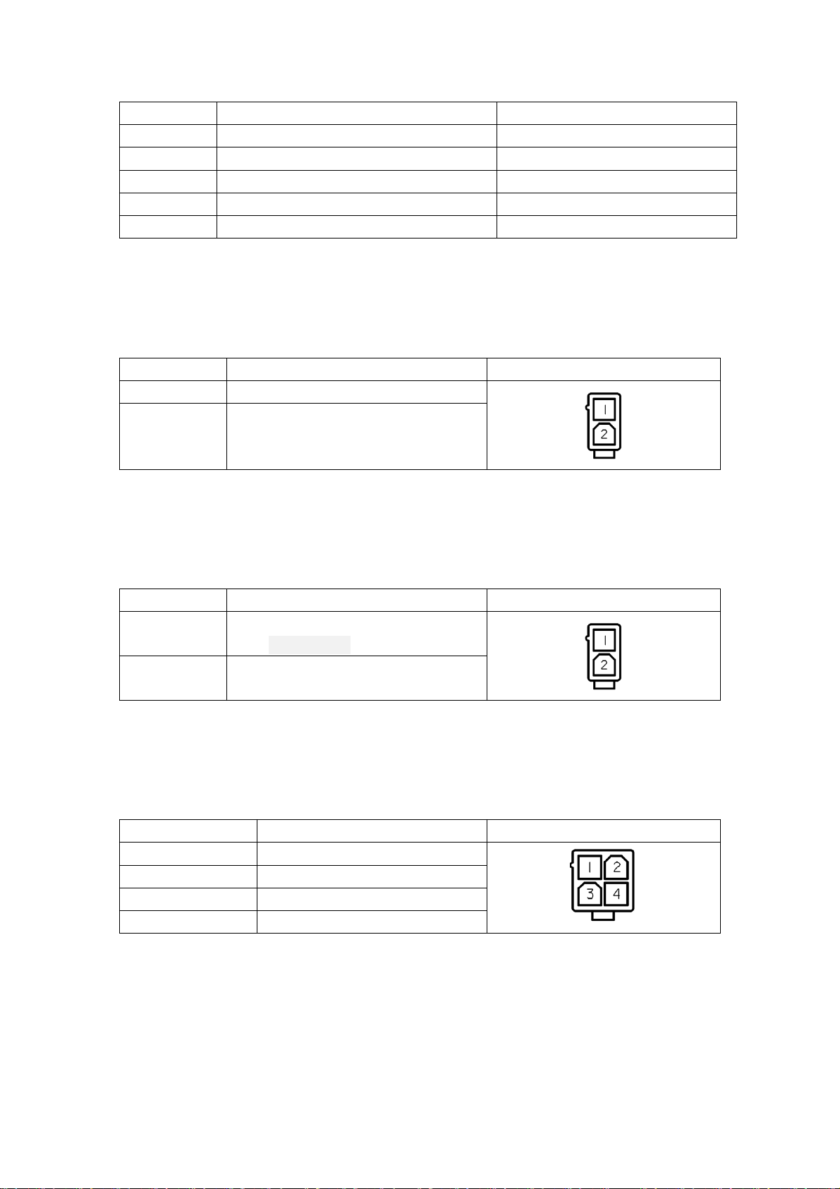
7.3.2.7 J6,Battery Access Port
Table14. Ifb1205 BatteryAccess Port
Pin
number Description Remark
1 BAT+
2 BAT-
7.3.2.8 J7,Charger Access Port
Table15. Ifb1205 Charger Access Port
Pin Description Remark

19
number
1 Charge+
2 Charge-
7.3.2.9 J8~J15,Standard Bus Port
Table16.Ifb1205 StandardPower Bus Port
Pin
number Description Remark
1 24V/BAT
2 12V
3 5V
4 GND
5 CANL
6 CANH
7 RXD
8 TXD
7.4 RHF 407 Development Board
Pleasecheck “RHF407usermanual”.
8User Extend
Hardwarein the robot canbeextendingthroughmanyways:
8.1 Bus Extend
Theequipmentwhichhave CANbusportcanaccess busthrough8PINstandard
ports ontheIFB1205board, and realizeequipmentconnection. Meanwhile,itcanrealize
connecttwoeach other which haveRS232portthrough8PINstandardports onthe
IFB1205board.
8.2 RHF407 Extend
TheRHF407developmentboardhaslots ofsource,itcanaccess variousequipment.
Followingsource:CAN×2,RS232×2,TTL*1,RS485×1,SPI×1,I2C×1,ADC×8,
DAC×2,PWM×8,LED×2,button×2,independenceI/O×24,repeatuseI/O×29, TF
cardport×1,RTC spare battery,RepeatuseTFTLCD port×1.
Table of contents


