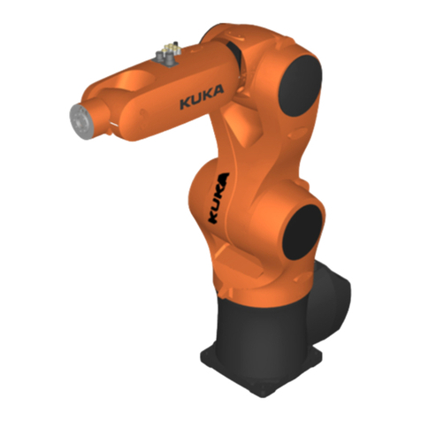
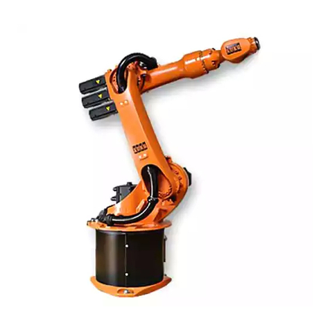
Kuka KR 300-2 PA User manual

Robots
KR 300-2 PA, KR 470-2 PA
Assembly Instructions
KUKA Roboter GmbH
Issued: 16.03.2016
Version: MA KR 300 470-2 PA V5
KR 300-2 PA,
KR 470-2 PA

KR 300-2 PA, KR 470-2 PA
2 / 125 Issued: 16.03.2016 Version: MA KR 300 470-2 PA V5
© Copyright 2016
KUKA Roboter GmbH
Zugspitzstraße 140
D-86165 Augsburg
Germany
This documentation or excerpts therefrom may not be reproduced or disclosed to third parties without
the express permission of KUKA Roboter GmbH.
Other functions not described in this documentation may be operable in the controller. The user has
no claims to these functions, however, in the case of a replacement or service work.
We have checked the content of this documentation for conformity with the hardware and software
described. Nevertheless, discrepancies cannot be precluded, for which reason we are not able to
guarantee total conformity. The information in this documentation is checked on a regular basis, how-
ever, and necessary corrections will be incorporated in the subsequent edition.
Subject to technical alterations without an effect on the function.
Translation of the original documentation
KIM-PS5-DOC
Publication: Pub MA KR 300 470-2 PA (PDF) en
Book structure: MA KR 300 470-2 PA V5.1
Version: MA KR 300 470-2 PA V5

3 / 125Issued: 16.03.2016 Version: MA KR 300 470-2 PA V5
Contents
1 Introduction .................................................................................................. 5
1.1 Industrial robot documentation ................................................................................... 5
1.2 Representation of warnings and notes ...................................................................... 5
2 Purpose ........................................................................................................ 7
2.1 Target group .............................................................................................................. 7
2.2 Intended use .............................................................................................................. 7
3 Product description ..................................................................................... 9
3.1 Overview of the robot system .................................................................................... 9
3.2 Description of the robot .............................................................................................. 9
4 Technical data .............................................................................................. 13
4.1 Basic data ..................................................................................................................13
4.2 Axis data .................................................................................................................... 14
4.3 Payloads ....................................................................................................................16
4.4 Mounting base data ................................................................................................... 20
4.5 Transport dimensions ................................................................................................ 21
4.6 Plates and labels ........................................................................................................ 22
4.7 Stopping distances and times .................................................................................... 25
4.7.1 General information .............................................................................................. 25
4.7.2 Terms used ........................................................................................................... 26
4.7.3 Stopping distance and stopping times for KR 300 PA .......................................... 27
4.7.3.1 Stopping distances and stopping times for STOP 0, axis 1 to axis 3 .............. 27
4.7.3.2 Stopping distances and stopping times for STOP 1, axis 1 ............................. 28
4.7.3.3 Stopping distances and stopping times for STOP 1, axis 2 ............................. 30
4.7.3.4 Stopping distances and stopping times for STOP 1, axis 3 ............................. 32
4.7.4 Stopping distance and stopping times for KR 470 PA .......................................... 32
4.7.4.1 Stopping distances and stopping times for STOP 0, axis 1 to axis 3 .............. 32
4.7.4.2 Stopping distances and stopping times for STOP 1, axis 1 ............................. 33
4.7.4.3 Stopping distances and stopping times for STOP 1, axis 3 ............................. 35
4.7.4.4 Stopping distances and stopping times for STOP 1, axis 2 ............................. 36
5 Safety ............................................................................................................ 39
5.1 General ...................................................................................................................... 39
5.1.1 Liability .................................................................................................................. 39
5.1.2 Intended use of the industrial robot ...................................................................... 40
5.1.3 EC declaration of conformity and declaration of incorporation ............................. 40
5.1.4 Terms used ........................................................................................................... 41
5.2 Personnel ...................................................................................................................41
5.3 Workspace, safety zone and danger zone ................................................................. 42
5.4 Overview of protective equipment .............................................................................. 43
5.4.1 Mechanical end stops ........................................................................................... 43
5.4.2 Mechanical axis range limitation (optional) ........................................................... 43
5.4.3 Axis range monitoring (optional) ........................................................................... 43
5.4.4 Options for moving the manipulator without drive energy ..................................... 44
5.4.5 Labeling on the industrial robot ............................................................................. 44
5.5 Safety measures ........................................................................................................ 45
Contents

4 / 125 Issued: 16.03.2016 Version: MA KR 300 470-2 PA V5
KR 300-2 PA, KR 470-2 PA
5.5.1 General safety measures ..................................................................................... 45
5.5.2 Transportation ...................................................................................................... 46
5.5.3 Start-up and recommissioning .............................................................................. 46
5.5.4 Manual mode ........................................................................................................ 48
5.5.5 Automatic mode ................................................................................................... 48
5.5.6 Maintenance and repair ........................................................................................ 49
5.5.7 Decommissioning, storage and disposal .............................................................. 50
5.6 Applied norms and regulations .................................................................................. 50
6 Planning ........................................................................................................ 53
6.1 Mounting base for 175 mm concrete thickness ......................................................... 53
6.2 Mounting base for 200 mm concrete thickness ......................................................... 55
6.3 Machine frame mounting ........................................................................................... 57
6.4 Connecting cables and interfaces ............................................................................. 58
7 Transportation ............................................................................................. 61
7.1 Transporting the robot ............................................................................................... 61
8 Start-up and recommissioning ................................................................... 65
8.1 Mounting base for 175 mm concrete thickness ......................................................... 65
8.2 Mounting base for 200 mm concrete thickness ......................................................... 67
8.3 Installing the machine frame mounting assembly ...................................................... 69
8.4 Installing the robot ..................................................................................................... 69
8.5 Description of the connecting cables ......................................................................... 71
9 Options ......................................................................................................... 75
9.1 Release device (optional) .......................................................................................... 75
10 Appendix ...................................................................................................... 77
10.1 Tightening torques ..................................................................................................... 77
10.2 Safety data sheets ..................................................................................................... 77
10.2.1 Safety data sheet for Microlube GL 261 lubricating grease .................................. 77
10.2.2 Safety data sheet for Castrol Hyspin ZZ 46 hydraulic oil ...................................... 81
10.2.3 Safety data sheet for RV OIL SB150 lubricating oil .............................................. 87
10.2.4 Safety data sheet for LGEP 2 extreme pressure grease ...................................... 94
10.2.5 Safety data sheet for Optitemp RB 2 lubricating grease ...................................... 101
11 KUKA Service ............................................................................................... 115
11.1 Requesting support ................................................................................................... 115
11.2 KUKA Customer Support ........................................................................................... 115
Index ............................................................................................................. 123

5 / 125Issued: 16.03.2016 Version: MA KR 300 470-2 PA V5
1 Introduction
1Introduction
1.1 Industrial robot documentation
The industrial robot documentation consists of the following parts:
Documentation for the manipulator
Documentation for the robot controller
Operating and programming instructions for the System Software
Instructions for options and accessories
Parts catalog on storage medium
Each of these sets of instructions is a separate document.
1.2 Representation of warnings and notes
Safety These warnings are relevant to safety and must be observed.
This warning draws attention to procedures which serve to prevent or remedy
emergencies or malfunctions:
Notices These notices serve to make your work easier or contain references to further
information.
t
t
These warnings mean that it is certain or highly probable
that death or severe injuries will occur, if no precautions
are taken.
These warnings mean that death or severe injuries may
occur, if no precautions are taken.
These warnings mean that minor injuries may occur, if
no precautions are taken.
These warnings mean that damage to property may oc-
cur, if no precautions are taken.
These warnings contain references to safety-relevant information or
general safety measures.
These warnings do not refer to individual hazards or individual pre-
cautionary measures.
Procedures marked with this warning must be followed
exactly.
Tip to make your work easier or reference to further information.

6 / 125 Issued: 16.03.2016 Version: MA KR 300 470-2 PA V5
KR 300-2 PA, KR 470-2 PA

7 / 125Issued: 16.03.2016 Version: MA KR 300 470-2 PA V5
2 Purpose
2Purpose
2.1 Target group
This documentation is aimed at users with the following knowledge and skills:
Advanced knowledge of mechanical engineering
Advanced knowledge of electrical and electronic systems
Knowledge of the robot controller system
2.2 Intended use
Use The industrial robot is intended for handling tools and fixtures, or for process-
ing or transferring components or products. Use is only permitted under the
specified environmental conditions.
Misuse Any use or application deviating from the intended use is deemed to be misuse
and is not allowed. This includes e.g.:
Transportation of persons and animals
Use as a climbing aid
Operation outside the permissible operating parameters
Use in potentially explosive environments
Use in underground mining
2
s
For optimal use of our products, we recommend that our customers
take part in a course of training at KUKA College. Information about
the training program can be found at www.kuka.com or can be ob-
tained directly from our subsidiaries.
Changing the structure of the manipulator, e.g. by drilling
holes, etc., can result in damage to the components. This
is considered improper use and leads to loss of guarantee and liability enti-
tlements.
Deviations from the operating conditions specified in the
technical data or the use of special functions or applica-
tions can lead to premature wear. KUKA Roboter GmbH must be consulted.
The robot system is an integral part of a complete system and may
only be operated in a CE-compliant system.

8 / 125 Issued: 16.03.2016 Version: MA KR 300 470-2 PA V5
KR 300-2 PA, KR 470-2 PA

9 / 125Issued: 16.03.2016 Version: MA KR 300 470-2 PA V5
3 Product description
3.1 Overview of the robot system
The industrial robot consists of the following components:
Manipulator
Robot controller
Teach pendant
Connecting cables
Software
Options, accessories
3.2 Description of the robot
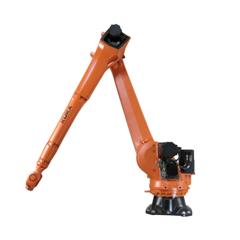
Overview This robot is designed as a 5-axis jointed-arm kinematic system. The structural
components of the robots are made of light alloy and iron castings. The axes
are driven by AC servomotors. A hydropneumatic counterbalancing system is
used to equalize the load moment about axis 2.
The robot consists of the following principal components (>>> Fig. 3-2 ):
Wrist
Arm
Link arm
Rotating column
Base frame
Counterbalancing system
Electrical installations
t
s
Fig. 3-1: Robot system KR 300, 470-2 PA
1 Robot 3 KR C4 robot controller
2 Connecting cables 4 Teach pendant KCP (KUKA
smartPAD)

10 / 125 Issued: 16.03.2016 Version: MA KR 300 470-2 PA V5
KR 300-2 PA, KR 470-2 PA
Wrist The robot variants KR 300 PA and KR 470 PA robots are equipped with a two-
axis wrist for rated payloads of 300 kg and 470 kg, respectively. The wrist is
fastened to the arm via a gear unit and motor and is driven by these. The main
components of the wrist are the swing frame, axis 6 motor and the correspond-
ing gear unit. The mounting flange embodies the output side of axis 6. The mo-
tor unit consists of a brushless AC servomotor with a permanent-magnet
single-disk brake and hollow-shaft resolver, both integrated. The permanent-
magnet single-disk brake performs a holding function when the servomotor is
at rest and contributes to the braking of axis 6 in the event of short-circuit brak-
ing (e.g. if one or more of the enabling switches is released while in Test
mode). Short-circuit braking must not be used to stop the robot under normal
circumstances. End effectors can be attached to the mounting flange of axis
6. The wrist is designed as a hollow-shaft wrist and features a through-hole
with a diameter of 60 mm.
The assembly also has a gauge mount with a gauge cartridge, through which
the mechanical zero of the axis can be determined by means of a dial gauge
or an electronic probe (accessory) and transferred to the controller.
Arm The arm is the transmission element between the wrist and the link arm. The
swing frame of the wrist is mounted on the arm via gear unit A5. This motor/
gear combination embodies axis 5, which cannot be freely controlled during
operation. The arm is driven by an AC servomotor via a gear unit that is in-
stalled between the arm and the link arm. This gear unit is also the bearing for
the arm. The maximum permissible swivel angle is mechanically limited by a
stop for each direction, plus and minus. The buffers are attached to the arm.
The corresponding stops are situated on the link arm.
Fig. 3-2: KR 300 470-2 PA: main assemblies
1 Wrist 5 Electrical installations
2 Arm 6 Base frame
3 Link arm 7 Rotating column
4 Counterbalancing system

11 / 125Issued: 16.03.2016 Version: MA KR 300 470-2 PA V5
3 Product description
Link arm The link arm is the assembly located between the arm and the rotating column.
It is mounted on one side of the rotating column via the gear unit of axis 2 and
is driven by an AC servomotor. During motion about axis 2, the link arm moves
about the stationary rotating column. The cable harness of the electrical instal-
lations is routed inside the link arm and is mounted in hinged clamps.
Rotating column The rotating column houses the motors of axes 1 and 2. The rotational motion
of axis 1 is performed by the rotating column. It is screwed to the base frame
via the gear unit of axis 1. The AC servomotor for driving axis 1 is mounted
inside the rotating column. The counterbearing for the counterbalancing sys-
tem is integrated into the rear of the rotating column housing. The fork slots
are also screwed to the rotating column if the robot is transported using a fork
lift truck.
Base frame The base frame is the base of the robot. It is screwed to the mounting base.
The interfaces for the electrical installations and the energy supply systems
(accessory) are housed in the base frame. The base frame and rotating col-
umn are connected via the gear unit of axis 1. The flexible tube for the electri-
cal installations and the energy supply system is accommodated in the base
frame.
Counterbal-
ancing system
The counterbalancing system is installed between the rotating column and the
link arm and serves to minimize the moments generated about axis 2 when the
robot is in motion and at rest. A closed, hydropneumatic system is used. The
system consists of two accumulators, a hydraulic cylinder with associated hos-
es, a pressure gauge and an accumulator safety valve as a safety element to
protect against overload. The accumulators correspond to category II, fluid
group 2, of the Pressure Equipment Directive.
Electrical installa-
tions
The electrical installations are described in Chapter .
Options The robot can be fitted and operated with various options, such as energy sup-
ply systems for axes 1 to 3, energy supply systems for axes 3 to 6, or working
range limitation systems. The options are described in separate documenta-
tion.

12 / 125 Issued: 16.03.2016 Version: MA KR 300 470-2 PA V5
KR 300-2 PA, KR 470-2 PA

13 / 125Issued: 16.03.2016 Version: MA KR 300 470-2 PA V5
4 Technical data
4 Technical data
4.1 Basic data
Basic data
Ambient temper-
ature, standard
Further information about temperatures, duty cycle, set-up, etc. can be ob-
tained from KUKA Technical Support. No restrictions in operating mode T1.
Connecting
cables
4
T
t
Type KR 300-2 PA
KR 470-2 PA
Number of axes 5
Work envelope volume 73.5 m³
Pose repeatability
(ISO 9283)
KR 300-2 PA ±0.08 mm
KR 470-2 PA ±0.08 mm
Work envelope refer-
ence point
Intersection of axis 6 with the mounting flange
face
Reach 3,150 mm
Weight of robot 2,150 kg
Weight of transport
frame
212 kg
Principal dynamic
loads
See “Loads acting on the mounting base”
Protection rating of the
robot
IP65
ready for operation, with connecting cables
plugged in (according to EN 60529)
Protection rating of the
wrist
IP65
Sound level < 72 dB (A) outside the working envelope
Mounting position Ground
Surface finish, paint-
work
Base (stationary) and counterbalancing system:
RAL 9005; moving parts: KUKA orange 2567
Operation 273 K to 328 K (0 °C to +55 °C)
Storage and
transportation
233 K to 333 K (-40 °C to +60 °C)
Start-up In the case of start-up in the range of 273 K to
288 K (0 °C to +15 °C), the robot may have to be
warmed up. Other temperature limits available on
request.
Ambient conditions DIN EN 60721-3-3,
Class 3K3
Cable designation Connector designa-
tion Interface with robot
Motor cable X20.1 - X30.1 Harting connectors
at both ends
Motor cable X20.4 - X30.4 Harting connectors
at both ends

14 / 125 Issued: 16.03.2016 Version: MA KR 300 470-2 PA V5
KR 300-2 PA, KR 470-2 PA
For detailed specifications of the connecting cables, see (>>> 6.4 "Con-
necting cables and interfaces" Page 58).
4.2 Axis data
Axis data The following data are valid for the robot KR 300-2 PA.
The following data are valid for the robot KR 470-2 PA.
* Maximum value, referred to the link arm, depending on the position of axis 2
The direction of motion and the arrangement of the individual axes may be not-
ed from the diagram (>>> Fig. 4-1 ).
Control cable X21 - X31 HAN 3A EMC
at both ends
Ground conductor /
equipotential bonding
16 mm2
(can be ordered as an
option)
M8 ring cable lug
at both ends
Cable lengths
Standard 7 m, 15 m, 25 m, 35 m, 50 m
Minimum bending radius 10x D
Cable designation Connector designa-
tion Interface with robot
Axis Range of motion, software-
limited Speed with
rated payload
1 +/-185° 97.5 °/s
2 +20° to -130° 91.0 °/s
3 +155° to -0°* 89.0 °/s
5 Axis not actively selectable
6 +/-350° 177.0 °/s
Axis Range of motion, software-
limited Speed with
rated payload
1 +/-185° 84.0 °/s
2 +20° to -130° 78.0 °/s
3 +155° to -0°* 73.0 °/s
5 Axis not actively selectable
6 +/-350° 177.0 °/s

15 / 125Issued: 16.03.2016 Version: MA KR 300 470-2 PA V5
4 Technical data
Working
envelope
The diagram (>>> Fig. 4-2 ) shows the shape and size of the working enve-
lope.
The reference point for the working envelope is the intersection of axis 6 with
the mounting flange face.
Fig. 4-1: Direction of rotation of robot axes

16 / 125 Issued: 16.03.2016 Version: MA KR 300 470-2 PA V5
KR 300-2 PA, KR 470-2 PA
4.3 Payloads
Payloads
Fig. 4-2: Working envelope: KR 300 470 PA
Robot KR 300-2 PA KR 470-2 PA
Wrist Hollow-shaft
wrist
Hollow-shaft
wrist

17 / 125Issued: 16.03.2016 Version: MA KR 300 470-2 PA V5
4 Technical data
Load center of
gravity P
For all payloads, the load center of gravity refers to the distance from the face
of the mounting flange on axis 6. Refer to the payload diagram for the nominal
distance.
Payload diagram
Rated payload 300 kg 470 kg
Distance of the load center of grav-
ity Lz
300 mm 300 mm
Distance of the load center of grav-
ity Lxy
100 mm 100 mm
Permissible moment of inertia 150 kgm2235 kgm2
Max. total load 350 kg 520 kg
Supplementary load, arm 50 kg 50 kg
Supplementary load, link arm 0 kg 0 kg
Supplementary load, rotating col-
umn
0 kg 0 kg
Fig. 4-3: Payload diagram for KR 300-2 PA

18 / 125 Issued: 16.03.2016 Version: MA KR 300 470-2 PA V5
KR 300-2 PA, KR 470-2 PA
Mounting flange
*The inner locating diameter is ø 125 H7. This deviates from the standard.
This loading curve corresponds to the maximum load ca-
pacity. Both values (payload and mass moment of iner-
tia) must be checked in all cases. Exceeding this capacity will reduce the
service life of the robot and overload the motors and the gears; in any such
case the KUKA Roboter GmbH must be consulted beforehand.
The values determined here are necessary for planning the robot application.
For commissioning the robot, additional input data are required in accor-
dance with the operating and programming instructions of the KUKA System
Software.
The mass inertia must be verified using KUKA.Load. It is imperative for the
load data to be entered in the robot controller!
Fig. 4-4: Payload diagram for KR 470-2 PA
Mounting flange similar to DIN/ISO 9409-1-A160*
Screw grade 10.9
Screw size M12
Grip length 1.5 x nominal diameter
Depth of engagement min. 15 mm, max. 19.5 mm
Locating element 10 H7
Through-hole for
energy supply system
ø 60 mm

19 / 125Issued: 16.03.2016 Version: MA KR 300 470-2 PA V5
4 Technical data
The mounting flange is depicted (>>> Fig. 4-5 ) with axis 6 in the zero posi-
tion. The symbol Xmindicates the position of the locating element (bushing) in
the zero position.
Supplementary
load
The robot can carry supplementary loads on the arm. When mounting the sup-
plementary loads, be careful to observe the maximum permissible total load.
The dimensions and positions of the installation options can be seen in the di-
agram. All other threads and holes on the robot are not suitable for attaching
additional loads .
Fig. 4-5: Mounting flange
1 Fitting length
2 Disruptive contour of screw heads

20 / 125 Issued: 16.03.2016 Version: MA KR 300 470-2 PA V5
KR 300-2 PA, KR 470-2 PA
4.4 Mounting base data
Loads acting on
the mounting
base
The specified forces and moments already include the payload and the inertia
force (weight) of the robot.
Fig. 4-6: Supplementary load on arm
1 Axis 3 3 Interference contour on right
2 Fastening thread
Fig. 4-7: Loads acting on the foundation
Type of load Force/torque/mass
Fv= vertical force Fv normal = 36,000 N
Fv max = 40,500 N
Fh= horizontal force Fh normal = 10,500 N
Fh max = 23,500 N
This manual suits for next models
1
Table of contents
Other Kuka Robotics manuals

Kuka
Kuka IONTEC KR 20 R3100 User manual

Kuka
Kuka KR 350 Guide

Kuka
Kuka ready2 educate User manual

Kuka
Kuka KR 20-3 User manual

Kuka
Kuka iiQKA LBR iisy User manual

Kuka
Kuka LBR iisy User manual

Kuka
Kuka KR 30-3 Operation instructions

Kuka
Kuka KUKA.EthernetKRL 2.2 User manual

Kuka
Kuka VisionTech 2.1 User manual

Kuka
Kuka KR 30 HA User manual