cherry creek systems NIC User manual

1 of 11
Network Irrigation Controller
“NIC”
Jobbing w/ Magnets
Version A.28
CHEAT SHEET

2 of 11
K
Ke
ey
yC
Co
on
nc
ce
ep
pt
ts
s
*
**
**
*R
Re
ea
ad
dt
th
hi
is
sF
Fi
ir
rs
st
t!
!*
**
**
*
It is advisable that this order is followed when working through the
manual and setting up your boom:
1. Key Concepts
2. Initial Power Up
3. Diagnostics
4. Setup
The
Network Irrigation Controller
(hereafter NIC) was designed to provide
flexibility and control while maintaining a simple menu-based programming
system. While still sophisticated, the NIC still attempts to tailor to the grower.
Through the various programmable speeds along with left and right solenoid
control, the NIC allows operators to manipulate water usage and time needed
when watering crops. The controller’s advanced memory features allow an array
of customized options for programming. Growers will find the ease of use and
the accuracy of the controller reassuring, as it can be taught to anyone with very
little training.
The NIC can hold up to
14 different Time Zones
, each containing a specific
start and end time. These Time Zones can all be run simultaneously or
separately and can be programmed with individual, customized time delays
(
Intervals
).
After the time zones are established each one may be programmed with “
Jobs”
.
The NIC is able to store up to 60 “Jobs” for each direction, in each Time Zone.
Each job within a Time Zone can have its own speed as well as solenoid valve
pattern giving you a vast array of watering options.
As you set up your NIC for the first time, read through each section of this
manual before implementing the steps described therein. This will help eliminate
unnecessary confusion and frustration. If you need help with terms, please refer
to the definitions section at the end of this manual.
T
Ti
im
me
eZ
Zo
on
ne
e:
:
This is a given period of time. Your NIC uses a 24 hour format:
1:00 PM = 13:00 10:00 AM = 10:00
12:00 AM = 00:00 10:00 PM = 22:00

3 of 11
K
Ke
ey
yp
pa
ad
d:
:
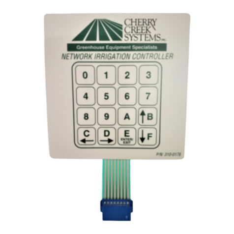
0-9 = Data Entry
E = Enter or Exit
B = Up / Increase
F = Down / Decrease
C = Left / Forward
D = Right / Back
J
Jo
ob
bb
bi
in
ng
g:
:
Basically, there are 4 steps:
1. Set-up Home Position (Home stop)
2. Set-up Away Position (Away stop)
3. Set-up the number of Jobs to be executed (number of Job magnets)
4. Give the Boom the Crop watering instructions
JOB 3
JOB 1
JOB 1
JOB 2
JOB 3
JOB 2
JOB
#
02
Magnet
JOB
#
03
Magnet
Double Rail Boom
t
racks (rails)
AWAY Position Magnet
(End of JOB 03)
HOME Position Magnet
(Start of JOB 01)

4 of 11
O
Op
pe
er
ra
at
ti
io
on
ns
s
_
__
__
__
__
__
__
__
__
__
__
__
__
__
__
__
__
__
__
__
__
__
__
__
__
__
__
__
__
__
__
__
__
__
__
__
__
__
__
__
__
__
_
M
Ma
an
nu
ua
al
lM
Mo
od
de
eP
Pr
ro
og
gr
ra
am
mm
mi
in
ng
g(
(J
Jo
ob
bs
s)
)
(Main, 2, 1)
* There are up to 60 JOBS that can be programmed in the Manual Mode *
In order to function properly, the Number of JOBS programmed must
correspond with the Number of Job magnets on the rail. If this is not
done, the “JOB COUNT ERROR” will appear on the screen and stop the
Booms operation until corrected. JOB 01 starts at the Home Magnet
and end when the Boom sees the first JOB Magnet (JOB 02 Magnet).
JOB 02 starts at the first JOB magnet and ends at the next JOB
Magnet…..et cetera…..
As shown in drawing below:
Quick Menu
/
Keypad Number
Reference
JOB 3
JOB 1
JOB 1
JOB 2
JOB 3
JOB 2
AWAY
Position Magnet
(End of JOB 03)
HOME
Position
Magnet
(Start of JOB #01)
JOB #02
Magnet
JOB #03
Magnet
Double Rail
Boom
tracks (rails)

5 of 11
1. From the Main Menu press 2 for Manual. The following screen will appear:
MANUAL MODE:
ENTER 1 FOR JOBS
ENTER 7 TO BEGIN
ENTER E TO EXIT
2. Press “1” to enter the Jobs Programming screen.
3. The black cursor will scroll thru the screen by pressing “F” to move
forward, and “D” to move back.
Exploded view of the Manual Mode Programming Screen:
A)CLR B)GOTO C)+ D)-
JOB01 SPEED VALVES
AWAY 020 1234
HOME 010 5678
4. Program the Job as desired per the user application and press “F” to scroll
to the next Job for programming. If, for example, only JOB #01 is
needed, the cursor must toggle to the next Job (DO NOT program that
next Job), then press “E” to go to the Pass Count menu. If the cursor
is not toggled to the next Job screen, that last Job programmed will not
be saved and will not run. This will also result in a “JOB COUNT ERROR”
and stop the operation of the Boom until the problem is fixed.
To
CLEAR
the Job, press
“A” and follow prompts.
Press “B” to
GOTO
another Job number for programming.
Then press “C” to COPY this info to other Job numbers.
Enter the
Home
and
Away
speeds
here. 5 to 150 FPM (Feet-Per-Minute)
Enter
Valve Numbers
here by pressing
numbers 1 thru 8. Pressing the number
will toggle that
#
Solenoid ON & OFF.
Press
“C”
to go to the
next Job number.
Press “D” to go to the
previous Job number.

6 of 11
NUMBER OF JOBS 03
ENTER THE PASS COUNT
THEN F KEY TO ENTER
TOTAL PASS COUNT 005
5. Enter the Number of
Passes
that the Boom needs to run over the crop.
Remember that a Pass is defined by the user in the Set-Up menu. The
actual number of Passes that the Boom will make back and forth is
effected by the users definition of a “PASS”.
The
Pass Count
can be set from 001 to 099 passes. Depending on the
application, it is common to assign 2 to 10 passes to saturate the crop
below the Boom.
6. Press “F” to Save and Exit back to the Manual Mode main menu.
_
__
__
__
__
__
__
__
__
__
__
__
__
__
__
__
__
__
__
__
__
__
__
__
__
__
__
__
__
__
__
__
__
__
__
__
__
__
__
__
__
__
_
M
Ma
an
nu
ua
al
lM
Mo
od
de
eR
Ru
un
n(
(J
Jo
ob
bs
s)
)
(Main, 2, 7)
1. From Main menu press 2 for Manual. The following screen will appear:
MANUAL MODE:
ENTER 1 FOR JOBS
ENTER 7 TO BEGIN
ENTER E TO EXIT
2. Make sure that the Boom is started (BEGIN) when the
Home Magnet
Reader
is under the Home Magnet. To locate the boom at the home
position, go into the Diagnostics menu and send the Boom Home, the
Boom will stop under the Home magnet, ready for its next command.
3. Press
“7” to BEGIN the Manual Mode Run
. The screen will show
the following information during the Irrigation Cycle:
(NEXT PAGE)

7 of 11
Exploded view of the Manual Mode Run Screen:
MANUAL MODE: GO AWAY
JOB 01 SPEED 020
SOLENOIDS = 1 2 3 4 5 6 7 8
PASS 01 13:48:47
7.
Press “0” to SUSPEND
the Booms Manual Mode Run.
Press “0” again to RESUME
the Booms operation.
8.
Press “E” to STOP
the Boom and Exit to the Manual Mode menu.
_
__
__
__
__
__
__
__
__
__
__
__
__
__
__
__
__
__
__
__
__
__
__
__
__
__
__
__
__
__
__
__
__
__
__
__
__
__
__
__
__
__
_
A
Au
ut
to
oZ
Zo
on
ne
es
s(
(T
Ti
im
me
eA
Ac
ct
ti
iv
va
at
te
ed
dP
Pr
ro
og
gr
ra
am
mm
mi
in
ng
g)
)
(Main, 1, enter 1-E)
Auto Zone
= A specific period of time that will activate the Booms operation as
programmed.
Jobs
= Number of Jobs that the programmed Auto Zone will execute.
Start Time
= Time that the Boom will Start this Zones Auto Program execution.
.
Stop Time
= Time that the Boom will Stop this Zones Auto Program execution.
Interval
= Amount of minutes between Pass execution.
Pass
= Starts at Home, goes to Away, then turns around and comes back Home.
*
Unless programmed differently by the user under the Set-Up menu.
MODE is displayed here. DIRECTION OF TRAVEL is displayed here.
Current
PASS
that the Boom
is executing is displayed here.
Active
SOLENOIDS
are displayed here.
The Booms
SPEED
will be displayed here.
Current programmed
TIME displayed here.

8 of 11
1. From the Main Menu Press 1 (AUTO)
ENTER AUTO ZONE NUMB
1 THRU E TIME ZONE #
TO ENTER AUTO MODE
PRESS THE F KEY
2. Enter the Auto Zone Number 1 thru E (14 Zones total) to be programmed.
The following screen will appear:
Exploded view of the Auto Zone Main Menu:
0)ZONE= 01 1)JOBS= 03
2)STARTTIME = 00:00
3)STOPTIME = 00:00
4)INTERVAL= 010 MIN.
3. Press “1” to Enter the
“Job Programming”
menu. Program Jobs as
described in
“Manual Mode Programming”
section in this manual (page 18).
4. Press “2” to program a Start Time and then press “3” to program a Stop
Time for this Auto Zone. Program time in 24 hour format.
The following programming screen will appear:
TIME VARIABLE = 00:00
ENTER 24 HOUR FORMAT
F = ENTER NEW TIME
NEW TIME VAR. = 17:43
5. Press “F” to Save and Exit to the Auto Zone menu.
Press 2
to
Enter
the
Start Time menu
Press 1
to Enter the
JOBS
programming menu.
Program Jobs as described in
“Manual Mode
Programming”
section in this manual (page 18).
Press 4
to
Enter any
Interval
(
Time
)
value between 001 and 999 minutes
Press
3
to Enter the
Stop Time menu

9 of 11
6. Press “4” to enter the
Interval Menu
. The user will program the
Interval
Time and the Pass Count
in this menu.
The following programming screen will appear:
PASS INTERVAL = 000 MIN
CHANGE TIME = 0 TO 9
ENTER TIME = F KEY
NEW INTERVAL = 045 MIN
7. Enter needed
Interval Time
(001 to 255 min.). Press “F” to Save and Exit.
NUMBER OF JOBS 03
ENTER THE PASS COUNT
THEN F KEY TO ENTER
TOTAL PASS COUNT 002
8. Enter the
Pass Count
desired for this Auto Zone (000 to 099 passes).
9. Press “F” to Save and Exit to the
Auto Zone Menu
. Press “0” to enter
another Auto Zone program (1-E).
ENTER AUTO ZONE NUMB
1 THRU E TIME ZONE #
TO ENTER AUTO MODE
PRESS THE F KEY
10. Press “0” to enter another Auto Zone program (1-E).
11. Once all needed Auto Zones are programmed, press “F” in Auto Zone
Main Menu to enter the
Auto Mode Run Menu
.
TO CHANGE ACTIVE
ZONES 1 3 56 8 ABC E
PRESS KEYS 1 THRU E
0 KEY EXIT, F KEY RUN
***Program all needed Auto Zones before
Pressing “F” to enter the Auto Mode Menu***
12. Enter the number of Auto Zones desired (1 thru E) and press “F” to
RUN
.
Toggle the
ACTIVE AUTO
ZONES On & Off by
pressing
the
1
thru
E keys

10 of 11
Exploded view of the Auto Mode Idle Screen:
AUTO MODE: -02:36:51
JOB 01 SPEED 020
SOLENOIDS = 1 2 3 4 5 6 7 8
ZONE 01 13:48:47
Exploded view of the Auto Mode Run Screen:
AUTO MODE: GO AWAY
JOB 01 SPEED 020
SOLENOIDS = 1 2 3 4 5 6 7 8
ZONE 01 13:48:47
13.
Press “0” to SUSPEND
the Booms Auto Mode Run.
Press “0” again to RESUME
the Booms operation.
14.
Press “E” to STOP
the Boom and Exit to the Auto Mode menu.
MODE is displayed here.
Next
AUTO ZONE START
TIME
is displayed here
.
Current
Z
ONE
that the
s
creen
is showing is displayed here.
Active
SOLENOIDS
are displayed here.
The Booms
SPEED
will be displayed here.
Current programmed
TIME displayed here.
MODE is displayed here. DIRECTION OF TRAVEL is displayed here.
Current
PASS
/ ZONE
being executed by the
Boom displayed here.
Active
SOLENOIDS
are displayed here.
The Booms
SPEED
will be displayed here.
Current programmed
TIME displayed here.

11 of 11
*** Before calling Tech Service, please try to RESET the
Controller first. This will sometimes solve problems and is
an easy step to correcting the problem before calling Tech
Service. If the NIC is “locked-up”, this will usually work to get
the Controller functional again. Otherwise contact CCSI. ***
One way to RESET the controller is to press the RESET
button on the board (shown in the Mother Board diagram
on the “Wiring Diagrams” pages). If there is not a button,
there will be two pins; jump them together with the tip of a
flathead screwdriver and that will RESET the controller as
well. Another way of resetting it is by pressing 0 and F
simultaneously. The NIC will stop the present operation and
ask for a four-digit code. If you press (7638), the NIC will
perform a software reset. All information will be lost,
including all setup information. If you press (4273), the NIC
will perform a hardware reset. Again, all information will
be lost. If the wrong code is entered or E is pressed, the NIC
will resume operation where it left off.
Note: Resetting this way is helpful if you are having
difficulty making the remote keypad respond.
TECHNICAL ASSISTANCE:
If you have any questions
regarding the use of this program or any other Cherry Creek
Systems Product please call us at
…………………………………..
(719) 380-8373 ext. 206
OR
ccs@cherrycreeksystems.com
OR
info@cherrycreeksystems.com
OR
www.cherrycreeksystems.com
Table of contents
Other cherry creek systems Controllers manuals
