manuals.online logo
Brands
  1. Home
  2. •
  3. Brands
  4. •
  5. Controlli
  6. •
  7. Controllers
  8. •
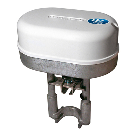
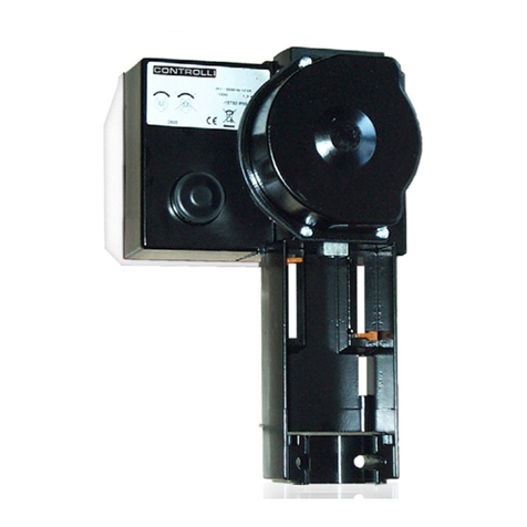
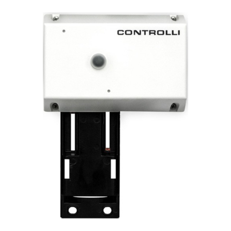
  9. Controlli MVC503 User manual

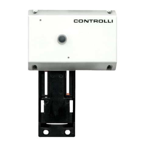
Controlli MVC503 User manual

CONTROLLI S.p.A. - 16010 Sant’Olcese (GE) - Italy
Tel. +39 010 73061 | Fax +39 010 7306870/871
[email protected] | www.controlli.eu
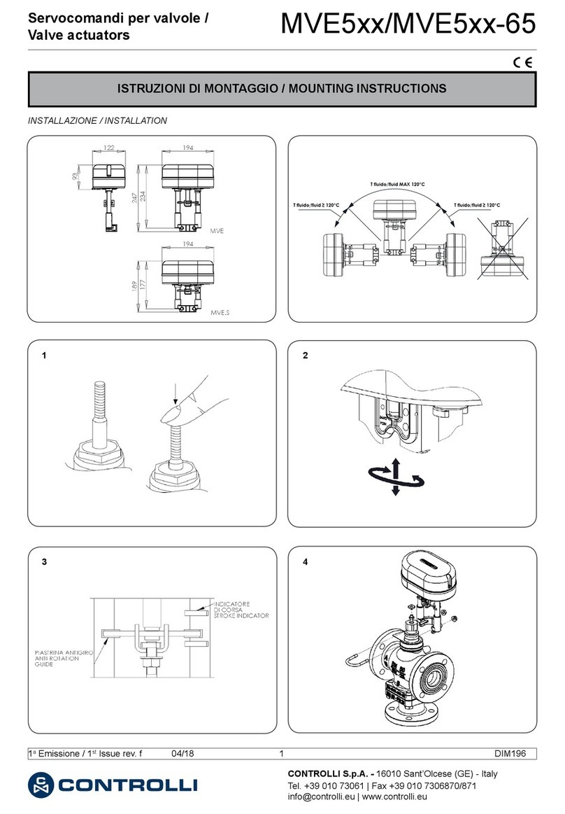
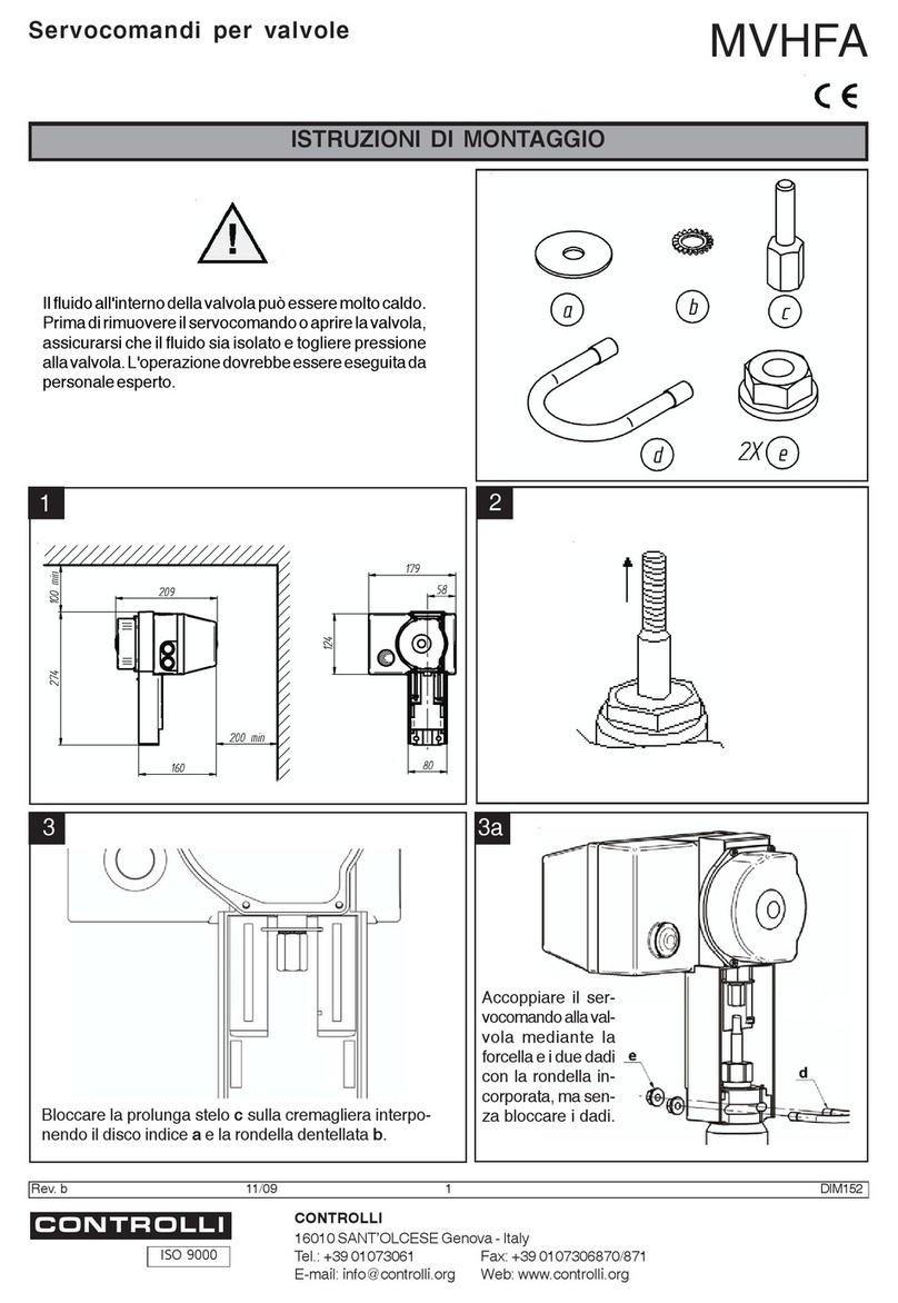
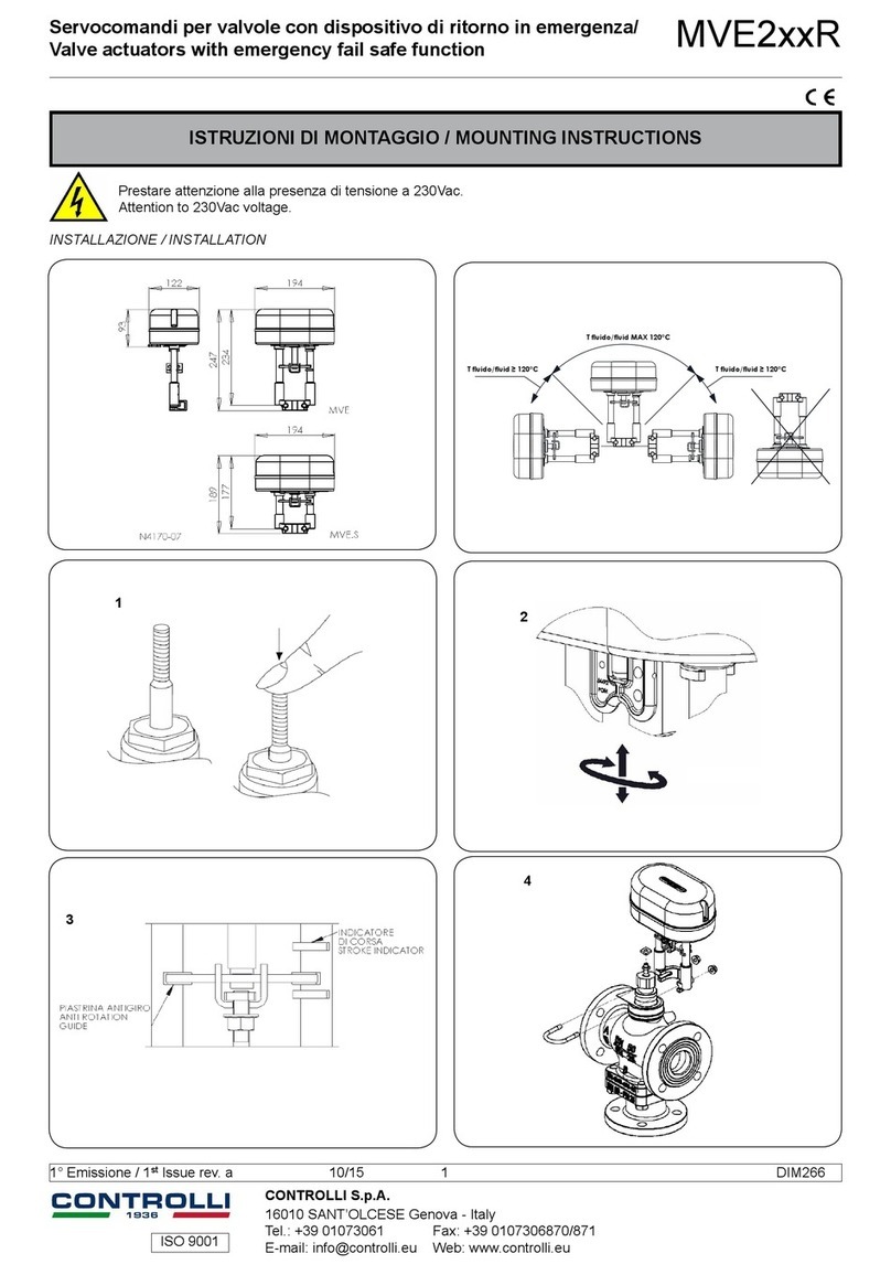
ISTRUZIONI DI MONTAGGIO / MOUNTING INSTRUCTIONS
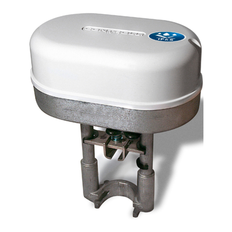
Servocomando Modulante
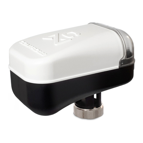
Modulating Actuator MVC503
INSTALLAZIONE / INSTALLATION
1aEmissione / 1st Issue rev. a 09/19 1 DIM301
VSB.T-VMB.T, 2-3TGB.B, 2-3TBB.T,
2TGA.BT
Allineare il foro dello spintore del servocomando con
il foro del dado (A), serrare la vite (B) attraverso il foro
non lettato del dato (A)
Align actuator spindle slot with the hole in locknut
(A), secure with bolt (B) through non threaded hole
in locknut (A)
1
2
A
B
1
2
3
75°
NO
YES
AVVERTENZE In caso di accoppiamento di MVC su una
valvola prodotta prima di Settembre 2019 in sostituzione
di un MVT occorre utilizzare il kit 55061.
VALVOLA (PRODUZIONE PRECEDENTE SETTEMBRE 2019) /
VALVE (PRODUCTION PREVIOUS SEPTEMBER 2019)
SERVOCOMANDO DA SOSTITUIRE /
ACTUATOR TO BE REPLACED
KIT DI SOSTITUZIONE /
REPLACEMENT KIT
VSB.T-VMB.T MVT203
MVT403
MVT503
550612-3TBB.T
2-3TGB.B
WARNING In case of MVC coupling on a valve produced
before September 2019 to replace an MVT, must be used
the 55061 kit.
Non utilizzare il servocomando se non accoppiato alla
valvola
Do not use the actuator if not coupled with the valve
NO
SI
YES
75°
SCHEMI DI COLLEGAMENTO / WIRING DIAGRAMS
1aEmissione / 1st Issue rev. a 09/19 2 DIM301
Blu/Blue
Bianco/White
Rosso/Red
Verde/Green
Giallo/Yellow
+
-
+
-
Segnale / Signal
+
-
24Vac
Feed back
SELEZIONE DIP SWITCH / DIP SWITCHES SELECTION
Il servocomando viene fornito con predisposi-
zione per segnale di comando 0...10 V- azione
diretta e posizione di ritorno completamente
esteso (DOWN); per modicare l’impostazione
operare come segue:
1. Rimuovere la vite ed aprire il coperchio
trasparente come indicato in gura.
2. Commutare i DIP secondo lo schema
seguente.
3. Le nuove impostazioni saranno attive al
prossimo ciclo di spegnimento/accesn-
sione.
The actuator is supplied prearranged for
0-10V control signal, direct action and fully
extended return position (DOWN); to modify
this setting, follow these instructions:
1. Remove the cover and the connector
(look at the following picture).
2. Change the DIP switches as indicated in
the following scheme.
3. The new settings will be active on the next
power off/on cycle.
DIP ON OFF (DEFAULT)
1 Azione INVERSA / Reverse action Azione DIRETTA / Direct action
2 2-10 V / 6-10 V 0-10 V / 0-5 V
3 Campi SEQ / SEQ range Campi NORM / range NORM
4 Non applicabile /Not applicable Corsa auto / Auto calibrated stroke
5 4-20 mA Campi in Tensione / Voltage range
6 Apprendimento corsa /Calibration Funzionamento Normale / Running
L’attuatore può essere accoppiato a valvole CONTROLLI tira/spingi
utilizzando l’autoapprendimento della corsa (DIP 4 OFF), oppure
a valvole CONTROLLI con molla di ritorno utilizzando la corsa ssa
(DIP 4 ON).
Apprendimento corsa (valido solo se DIP4 è OFF)
Questa funzione consiste nell’apprendere il tempo massimo di corsa
della vavola a cui il servocomando viene accoppiato, in modo da
poterla posizionare correttamente seguendo il segnale di coman-
do. Con attuatore alimentato è ripetibile ogni volta che il DIP 6 va
da OFF a ON e il DIP 4 è OFF. Durante il funzionamento normale è
The actuator can be coupled with push/pull CONTROLLI valves using
auto calibration stroke; or to CONTROLLI valves with spring return
using xed stroke. Actuators with xed stroke (DIP 4 ON) have only
reverse action.
Automatic stroke calibration (valid only for DIP n. 4 in OFF)
This function helps to calibrate the maximum valve time stroke, so
that the actuator can place the valve correctly following the control
signal. If the actuator is powered on, this action can be repeated
any time DIP 6 goes from OFF to ON and DIP 4 is OFF. During normal
operation, it is possible to choose the position of DIP 6: at each start
VALVOLE SENZA MOLLA / VALVES WITHOUT SPRING
VSB.T-VMB.T
3/4” .. 2”
CORSA/STROKE 5,5 mm
2-3TGB.B
1/2”
CORSA/STROKE 11,5 mm
2-3TBB.T
1/2” .. 2"
CORSA/STROKE 12 mm
2TGA.BT
3/4” .. 2"
CORSA/STROKE 8,5 mm
VALVOLE ALTRI COSTRUTTORI /
VALVES OF OTHER MANUFACTURERS
CORSA/STROKE max 12 mm
MODELLO / MODEL
MVC503 AG74-03
Le caratteristiche contenute in questa pubblicazione possono essere modifi cate senza preavviso
The performances stated in this sheet can be modifi ed without any prior notice
1aEmissione / 1st Issue rev. a 09/19 3 DIM301
possibile scegliere in quale posizione mantenere il DIP 6: ad ogni ac-
censione l’apprendimento sarà ripetuto se in ON; verrà invece man-
tenuto l’apprendimento precedente se in OFF.
Azione Diretta e Inversa
Attraverso il DIP 1 è possibile impostare il servocomando in azione
diretta (DIP1 in OFF) o inversa (DIP 1 in ON). In azione diretta e senza
segnale di comando la posizione dello spintore è verso l’alto (spin-
tore retratto) con uscita feedback a 2V, mentre in azione inversa e
senza segnale di comando la posizione dello spintore è verso il basso
con feedback 2V.
Impostazione Campi Segnale di Comando
Attraverso i DIP 2, 3 e 5 è possibile impostare 5 diversi campi di ingres-
so. Se il DIP 5 è in ON, il campo di ingresso è settato su 4-20 mA e i DIP
2 e 3 perdono signicato.
Se il DIP 5 è in OFF, i campi gestiti sono: 0-10/2-10 con DIP 3 in OFF,
0-5/6-10 con DIP 3 in ON.
Posizionamento iniziale
Viene eseguito ogni volta che l’attuatore viene alimentato e dopo
aver eseguito l’apprendimento della corsa. Questa operazione per-
mette al servocomando di partire da una posizione certa per poi se-
guire il segnale di comando. Tale posizione dipende dalla selezione
effettuata sul DIP 1 (DIP 4 in OFF).
Nel caso in cui il DIP 4 sia in ON, la posizione iniziale è con spintore
dell’MVC estratto (i servocomandi con valvole a corsa ssa hanno
solo l’azione inversa).
Funzione Stallo inatteso
Se viene riconosciuto un impuntamento nella corsa, questa funzione
ha lo scopo di sbloccarlo; l’attuatore verrà comandato in direzione
opposta per poi riprovare a raggiungere la posizione e verranno
eseguiti 3 tentativi. Nel caso non si fosse sbloccato dopo i primi 3
tentativi, dopo una pausa di 1 minuto vengono eseguiti ulteriori 3
tentativi.
Uscita feedback (2-10V)
Il servocomando dispone di un’uscita dedicata per fornire il segnale
di feedback della posizione presunta dell’attuatore. Questo segnale
può variare da 2 a 10 V.
Durante la fase di “Apprendimento corsa” e “Posizionamento
iniziale” il segnale rimane sso a 2 V. Durante la fase di ritorno in
emergenza il segnale di feedback rimane sso a 1 V.
Comando manuale
Per azionare il comando manuale rimuovere l’alimentazione, rimuo-
vere il coperchio trasparente e inserire una chiave esagonale da
3 mm nel foro frontale e ruotare la chiave sino a quando non si è
raggiunta la posizione desiderata.
up the stroke calibration will be carried out if DIP 6 is ON; it will be
maintained the previous stroke if DIP 6 is OFF.
Direct/Reverse action
Through DIP1 is possible to set direct or reverse action. In direct action
without control signal the actuator is fully retracted with feedback
set to 2V. With reverse action the actuator is fully exteded and the
feedback without control signal is 2 V in this position.
Setting Control Signal Fields
Through DIP 2,3 and 5 it is possible to set 5 different input ranges.
If DIP 5 is ON, the input range is set at 4-20mA and DIP 2 and 3 have no
meaning. If DIP 5 is OFF, the possible ranges are: 0-10/2-10 if DIP 3 is
OFF and 0-5/6-10 if DIP 3 is ON.
Initial Positioning
It is executed every time the actuator is powered and before to
have performed the learning of the race. This operation allows the
servocontrol to start from a certain position for then follow the com-
mand signal. This position depends on the selection made on DIP 1.
Unexpected stall condition
If an unexpected stop during the stroke occurs, this function has the
aim to make it disappear. The actuator will be driven in the opposite
direction and then it will try again to reach the position.
If it wa s not unl ocked af ter the rst 3 attempt s, after a 1 minute pause,
3 more attempts are made.
Feedback output signal (2-10V)
The actuator is equipped with a proper output to transmit the feed-
back signal relating to the supposed actuator position. This signal
can vary from 2 to 10V. During the “automatic stroke calibration”
and “Initial positioning” function it is set at 2V. During the emergency
positioning function the feedback signal is set to 1V.
Manual control
To activate the manual control, remove the power supply, remove
the transparent cover and insert a 3 mm hexagonal key into the front
hole and turn the key until the desired position is reached.
DESCRIZIONE DEI LEDS / LEDs DESCRIPTION
LED
FASE DI
APPRENDIMENTO
POSIZIONAMENTO
INIZIALE
POSIZIONAMENTO
UP
FINE CORSA UP
POSIZIONAMENTO
DOWN
FINE CORSA
DOWN
SERVOCOMANDO
FERMO
STALLO INATTESO
TENSIONE DI
ALIMENTAZIONE
BASSA
SERVOCOMANDO
SPENTO O SOTTO
RESET (TENSIONE
DI ALIMENTAZIONE
BASSA)
FUNZIONE
LIMITE CORSA
MASSIMA
GIALLO ON ON ON ON ON ON ON ON LAMPEGGIANTE
1Hz OFF ON
ROSSO ALTERNATO
5Hz
ALTERNATO
1Hz
OFF OFF LAMPEGGIANTE
1Hz ON OFF CONTEMPORANEO
5Hz
OFF OFF ON
VERDE LAMPEGGIANTE
1Hz ON OFF OFF OFF OFF OFF ON
Le caratteristiche contenute in questa pubblicazione possono essere modifi cate senza preavviso
The performances stated in this sheet can be modifi ed without any prior notice
Il dispositivo contiene componenti elettrici ed elettronici e non può essere smaltito con i riuti domestici. Vanno rispettate le normative locali sullo
smaltimento.
The device contains electrical and electronic components and is not allowed to be disposed of as household refuse. All locally valid regulations and
requirements must be observed.
1aEmissione / 1st Issue rev. a 09/19 4 DIM301
LEDs
CALIBRATION
PHASE
INITIAL
POSITIONING
UP
POSITIONING
END STROKE UP
DOWN
POSITIONING
END STROLE
DOWN
ACTUATOR
STOP
UNEXPECTED
STALL
LOW SUPPLY
VOLTAGE
ACTUATOR
OFF OR UNDER
RESET (SUPPLY
VOLTAGE LOW)
MAX STROKE
LIMIT PHASE
YELLOW ON ON ON ON ON ON ON ON BLINKING 1Hz OFF ON
RED ALTERNATING
5Hz
ALTERNATING
1Hz
OFF OFF BLINKING 1Hz ON OFF SIMULTANEOUS
5Hz
OFF OFF ON
GREEN BLINKING 1Hz ON OFF OFF OFF OFF OFF ON
Other Controlli Controllers manuals

Controlli MVC503R User manual

Controlli

Controlli MVC503R User manual

Controlli Energon NR9001 User manual

Controlli

Controlli Energon NR9001 User manual

Controlli MDL46 User manual

Controlli

Controlli MDL46 User manual

Controlli MVB2 Series User manual

Controlli

Controlli MVB2 Series User manual

Controlli MVC503R-MB User manual

Controlli

Controlli MVC503R-MB User manual

Controlli MDL Series User manual

Controlli

Controlli MDL Series User manual

Controlli W554C User manual

Controlli

Controlli W554C User manual

Controlli MVE5 Series User manual

Controlli

Controlli MVE5 Series User manual

Controlli MVE2 Series User manual

Controlli

Controlli MVE2 Series User manual

Controlli Energon User manual

Controlli

Controlli Energon User manual

Controlli MVHFA User manual

Controlli

Controlli MVHFA User manual

Controlli MVT203 User manual

Controlli

Controlli MVT203 User manual

Controlli MVE2XX User manual

Controlli

Controlli MVE2XX User manual

Controlli MVC503R-MB User manual

Controlli

Controlli MVC503R-MB User manual

Controlli MVH26 User manual

Controlli

Controlli MVH26 User manual

Controlli MVT5 Series User manual

Controlli

Controlli MVT5 Series User manual

Controlli MVE2 R Series User manual

Controlli

Controlli MVE2 R Series User manual

Controlli MVH56E User manual

Controlli

Controlli MVH56E User manual

Controlli SH 2 Series User manual

Controlli

Controlli SH 2 Series User manual

Controlli MVT5 Series User manual

Controlli

Controlli MVT5 Series User manual

Controlli MVT5 Series User manual

Controlli

Controlli MVT5 Series User manual

Controlli MVH56EA User manual

Controlli

Controlli MVH56EA User manual

Controlli MVE5 R Series User manual

Controlli

Controlli MVE5 R Series User manual

Controlli DG501C User manual

Controlli

Controlli DG501C User manual

Popular Controllers manuals by other brands

Pixsys ATR224 user manual

Pixsys

Pixsys ATR224 user manual

Samson TROVIS 6495-2 Mounting and operating instructions

Samson

Samson TROVIS 6495-2 Mounting and operating instructions

Geco GH10HA user manual

Geco

Geco GH10HA user manual

Remote Control RCEL005X instructions

Remote Control

Remote Control RCEL005X instructions

Atlantic TWVSC product manual

Atlantic

Atlantic TWVSC product manual

EUCHIPS DMX801 manual

EUCHIPS

EUCHIPS DMX801 manual

Munters TRIO User and installation manual

Munters

Munters TRIO User and installation manual

Zennio FANinBOX 110V 1CH Technical documentation

Zennio

Zennio FANinBOX 110V 1CH Technical documentation

Watlow ez-zone pm user guide

Watlow

Watlow ez-zone pm user guide

YASKAWA MOTOMAN-NX100 Function manual

YASKAWA

YASKAWA MOTOMAN-NX100 Function manual

BubblyNet C-IX8-24-DS00 manual

BubblyNet

BubblyNet C-IX8-24-DS00 manual

Macally KeyPoint user manual

Macally

Macally KeyPoint user manual

BEKA BA454D manual

BEKA

BEKA BA454D manual

CLIMAVENETA EVOLUTION instruction manual

CLIMAVENETA

CLIMAVENETA EVOLUTION instruction manual

Samsung SPC-7000 user manual

Samsung

Samsung SPC-7000 user manual

3M Touch Screen Controller EX 111 reference guide

3M

3M Touch Screen Controller EX 111 reference guide

Zennio MAXinBOX FC 0-10V VALVE user manual

Zennio

Zennio MAXinBOX FC 0-10V VALVE user manual

Mitsubishi Electric -MR-CV user manual

Mitsubishi Electric

Mitsubishi Electric -MR-CV user manual

manuals.online logo
manuals.online logoBrands
  • About & Mission
  • Contact us
  • Privacy Policy
  • Terms and Conditions

Copyright 2025 Manuals.Online. All Rights Reserved.