CHERUBINI BLUE BUS TDS Series User manual

MODULO DI COMANDO E CENTRALIZZAZIONE
PER TENDE DA SOLE
CONTROL AND CENTRALIZATION MODULE
FOR AWNINGS
STEUER- UND ZENTRALISIERUNGSMODUL
FÜR MARKISE
MODULE DE COMMANDE ET DE CENTRALISATION
POUR STORES
MÓDULO DE MANDO Y CENTRALIZACIÓN
PARA TOLDO
ISTRUZIONI - INSTRUCTIONS - EINSTELLANLEITUNGEN
INSTRUCTIONS - INSTRUCCIONES
Serie - Series - Baureihe - Série - Serie BLUE BUS TDS
BLUE BUS TDS RX
I
GB
D
F
E


25
Table of contents
- Product features ....................................................................................................................... p. 26
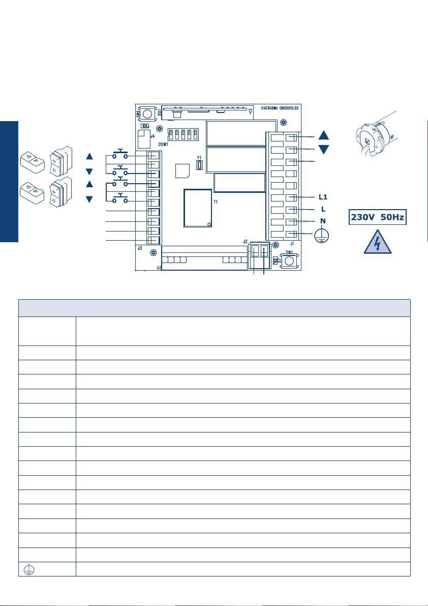
- Electrical connections ............................................................................................................... p. 26
- Legend ...................................................................................................................................... p. 26
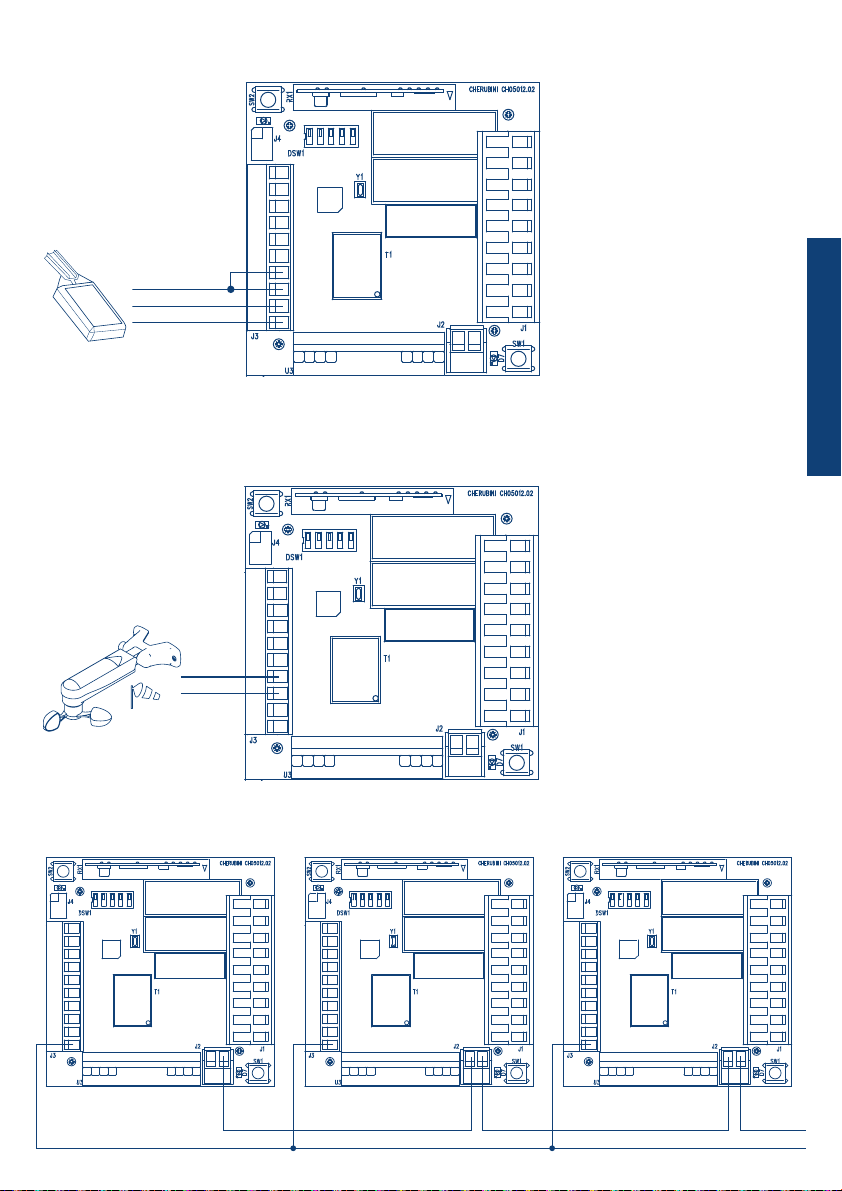
- Rain sensor connection ............................................................................................................. p. 27
- Wired wind sensor connection (WindTec SC) ............................................................................. p. 27
- Connection to the Cherubini 2-wire BUS ................................................................................... p. 27
- Blue Bus TDS module connection to motors with standard wiring ............................................ p. 28
- Blue Bus TDS module connection to white-wire motors ........................................................... p. 28
- Guarantee ................................................................................................................................. p. 29
- Installation notes ...................................................................................................................... p. 29
- Notes for the user ..................................................................................................................... p. 29
- Key to symbols .......................................................................................................................... p. 30
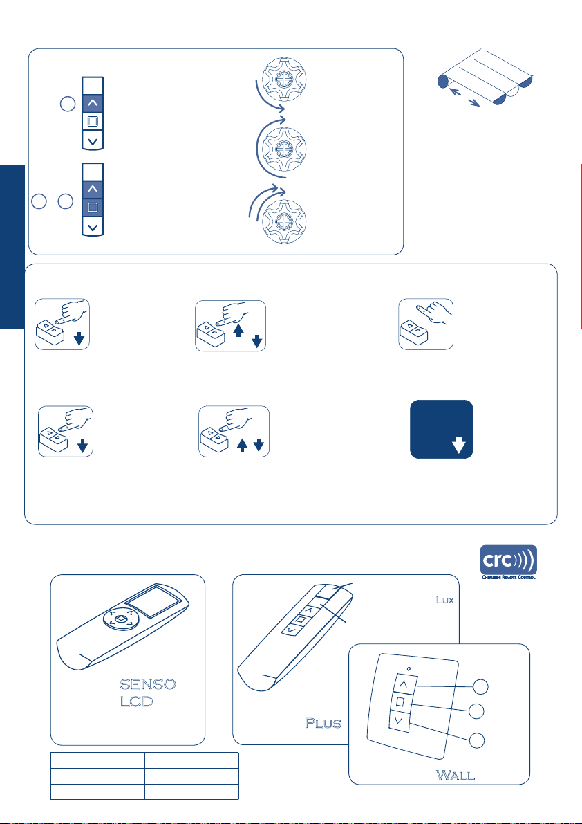
- Compatible remote controls (Blue Bus TDS RX) ........................................................................ p. 30
- Commands from a remote control (Blue Bus TDS RX) ............................................................... p. 31
- Command sequences example (Blue Bus TDS RX)..................................................................... p. 31
- Setting the rst remote control (Blue Bus TDS RX) .................................................................... p. 32
- Automatic disabling of the rst remote control setting function (Blue Bus TDS RX) ................. p. 32
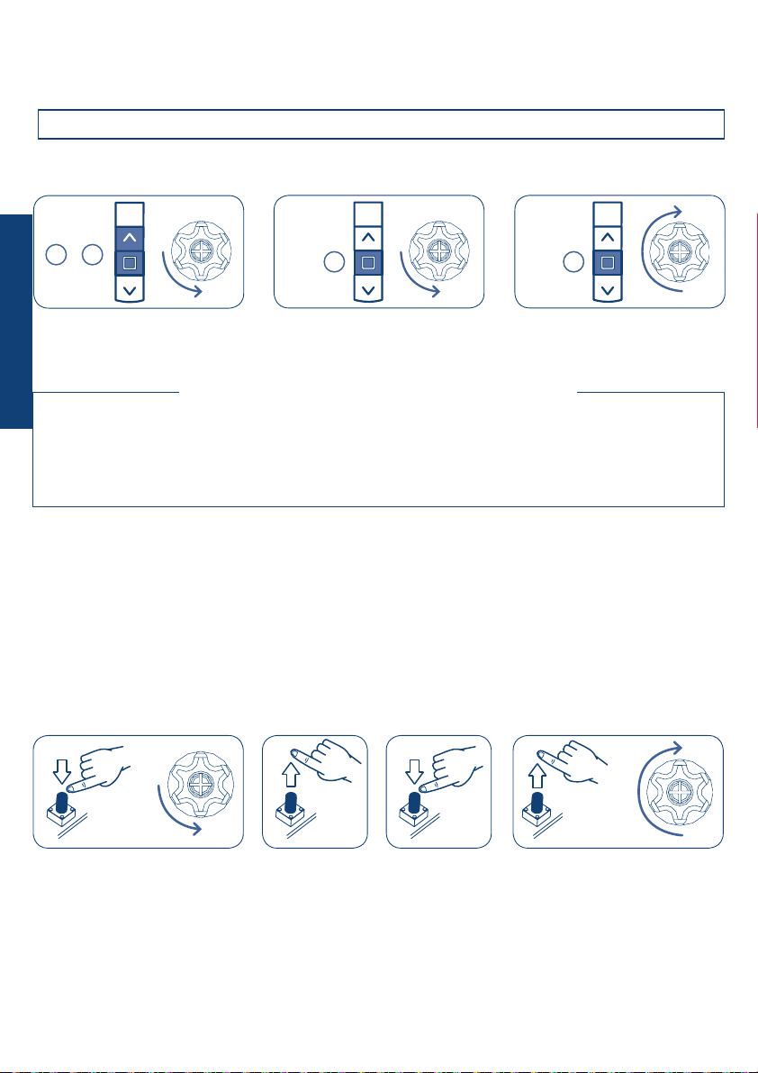
- Setting the rotation direction of the motor (Blue Bus TDS RX) .................................................. p. 32
- Setting of additional remote controls (Blue Bus TDS RX) ........................................................... p. 33
- Remote control memory clearing (Blue Bus TDS RX) ................................................................. p. 33
- Full memory clearing ................................................................................................................ p. 33
- Wind- and sun sensor WindTec/WindTec Lux (Blue Bus TDS RX) ................................................ p. 34
- Setting the wind sensor ............................................................................................................. p. 34
- Deleting the wind sensor ........................................................................................................... p. 34
- Enable / disable the sun sensor (WindTec Lux) .............................................................................. p. 35
- Test mode (WindTec/WindTec Lux)............................................................................................... p. 35
- Wind sensor WindTec SC (Blue Bus TDS - Blue Bus TDS RX)....................................................... p. 36
- Test for wind-sensor (WindTec SC) ............................................................................................ p. 36
- Mistral sensor (Blue Bus TDS RX)............................................................................................... p. 37
- Setting the mistral sensor .......................................................................................................... p. 37
- Deleting the mistral sensor......................................................................................................... p. 37
- Rain sensor (Blue Bus TDS - Blue Bus TDS RX)........................................................................... p. 38
- Special functions (Blue Bus TDS RX) short-term setting of a remote control.............................. p. 38
- Conguration of the Blue Bus TDS module............................................................................p. 39-40
- Commands from the control switch .......................................................................................... p. 40
- Operation of local commands..................................................................................................... p. 40
- Operation of centralized commands ........................................................................................... p. 41
- Special commands (using modules A510008) .............................................................................. p. 42
- Technical features ..................................................................................................................... p. 43
- Connection diagrams
-
Centralization of Blue Bus TDS modules in sequence with a 2-wire BUS for motors with standard wiring
p. 44
- Centralization of Blue Bus TDS modules in a sequence with a 2-wire BUS for white wire motors ....... p. 45
- Centralization with a Blue Bus TDS module and A510008 for motors with standard wiring ............... p. 46
ENGLISH

26
ELECTRICAL CONNECTIONS
PRODUCT FEATURES
MOTORE
COM
CENTR CMD
LOC CMD
SENS IN
SENS COM
+12V
0V
RESET/AUX
LED
SEQ IN SEQ OUT
The Blue Bus TDS control and centralisation module is indicated for the control of Cherubini mechanical
and electronic motors intended for awnings applications.
Legend
RESET/AUX Reset/Aux key (resets wind alarm /reverses motor rotation direction/clears remote
control memory)
LED Led warning lamps for wind test function/wind alarm
CENTR CMD Input push buttons for centralised motor control
LOC CMD Input push buttons for local motor control
SENS IN Climatic sensor input signal (wind/rain sensor)
SENS COM Climatic sensor common signal (wind/rain sensor)
+12V +12 V DC output
0V Reference 0V output
SEQ IN Cherubini wire BUS input signal
SEQ OUT Cherubini wire BUS output signal
pMotor ascent control clean output contact
qMotor descent control clean output contact
COM Motor control common signal
L1 Phase voltage power output from the integrated current sensor
L Phase voltage power input
N Neutral voltage power input
Power input earth connection
MOTOR
ENGLISH

27
ITALIANO
RAIN SENSOR CONNECTION
WIRED WIND SENSOR CONNECTION (WINDTEC SC)
CONNECTION TO THE CHERUBINI 2-WIRE BUS
SENS IN
SENS COM
The rain-sensor operational
mode may be set using the
DSW1 Dip Switch.
The wind-speed threshold
may be set using the DSW1
Dip Switch.
SEQ OUT SEQ IN
0V
SEQ OUT SEQ OUTSEQ IN
0V 0V
SENS IN/COM (BLUE)
+12V (WHITE)
0V (YELLOW)
WINDTEC SC
RAIN SENSOR
ENGLISH

28
Note: centralised control is transmitted from one Blue Bus TDS module to the other by the Cherubini
2-wire BUS.
Maximum length of the wire from one card to the other
Unshielded wire 10 m
Shielded or twist wire 50 m
BLUE BUS TDS MODULE CONNECTION TO MOTORS
WITH STANDARD WIRING
BLUE BUS TDS MODULE CONNECTION TO WHITE-WIRE MOTORS
Note 1: for complete installation examples refer to the diagrams at the back of the manual.
Note 2: the the output connection from L1 is used to propagate the centralised control and the
alarms signals through the Cherubini 2-wire BUS for the purposes of motor movement.
COM
COM
BLACK
BROWN
BROWN
BLUE
BROWN
WHITE
BROWN
BLUE
YELLOW-GREEN
YELLOW-GREEN
BLUE
YELLOW-GREEN
YELLOW-GREEN
BLUE
ENGLISH

29
- This unit should not be used by children or persons with reduced psycho-physical capacity unless
supervised or instructed by an adult on its use and operation.
- Inspect the system regularly for any signs of damage or wear. Do not use the unit if it is in need of
repair.
- ATTENTION: keep this instruction manual and comply with all important safety regulations herein.
Failure to comply with these regulations could cause harm and serious accidents.
GUARANTEE
INSTALLATION NOTES
NOTES FOR THE USER
This product is guaranteed for 24 months from the date of manufacture indicated inside. If, during that
period, the equipment does not work properly due to a defective component, it will be repaired or
replaced at the discretion of the manufacturer. The warranty does not cover the integrity of the plastic
container. The warranty will be honoured at the manufacturer’s facilities.
The product fullls the essential requirements of Safety, Electromagnetic Compatibility and use of the
spectrum allocated to Radiocommunication of the Directive 1999/05/EC.
- Only professional technicians must perform installation, complying with all safety instructions,
especially those regarding electrical connections.
- To avoid short circuits, arrange an automatic bipolar switch with opening distance of the contacts
of at least 3 mm before the circuit.
- We recommend reading the instructions attached to the motors you are using carefully, before using
the Blue Bus TDS module.
ENGLISH

30
KEY TO SYMBOLS
COMPATIBLE REMOTE CONTROLS (BLUE BUS TDS RX)
- short motor
rotation in one
direction
- long motor
rotation in other
direction
- double short
rotation
+
AB
A
ON THE REMOTE CONTROL
Press button A
Press buttons A and B
at the same time
ON THE CONTROL SWITCH
- press the DOWN button
on the LOC CMD switch
- keep the DOWN
button
pressed for 1 second on the
CENTR CMD switch
- press the UP or DOWN button
on the LOC CMD switch
- press the UP and DOWN
button
on the
CENTR CMD switch quickly one after
the other (0.5 seconds)
- release the button formerly
pressed on the LOC CMD switch
- send a DOWN command
(automatically) from the SEQ OUT
connector (centralized command)
DOWN
CENTR CMD
DOWN
LOC CMD
LOC CMD
LOC CMD
DOWN
UP /
1 sec Sequenza (0,5 sec)
CENTR CMD
UP DOWN DOWN
SEQ OUT
down
up
Skipper
channel selector
Skipper
LED -
display -
Skipper
Skipper
Skipper
Skipper
*check the specic instruction
book
Skipper
down
C
stop
B
up
A
Control unit type Product Code
Blue Bus TDS A510025
Blue Bus TDS RX A510026
ENGLISH

31
COMMAND SEQUENCES EXAMPLE (BLUE BUS TDS RX)
COMMANDS FROM A REMOTE CONTROL (BLUE BUS TDS RX)
Most of the command sequences have three distinct steps, at the end of which the motor indicates if
the step has been concluded positively or not, by turning in different ways. This section is provided to
demonstrate the motor indications. The buttons must be pressed as shown in the sequence, without
taking more than 4 seconds between one step and the next. If more than 4 seconds are taken, the
command is not accepted and the sequence must be repeated.
Command sequence example:
It is possible to control the Blue Bus TDS RX control unit by means of a Cherubini remote control. Follow
the instructions shown in the following pages for programming. As far as all programming sequences
are concerned, we recommend also consulting the remote control instruction leaet.
As we can see from the example, when the sequence ends positively, the motor returns to its starting
position in one long rotation. In fact, two short rotations in the same direction correspond to one long
rotation in the opposite direction.The motor returns to the starting position even when the sequence is
not completed; in this case by performing one or two short rotations.
Example of a wrong sequence:
Step 1
Step 1
> 4 sec repeat the
sequence
repeat the
sequence
+
AB
+
AB
Step 2
B
Step 1 Step 3
B
+
AB
Step 2
B
> 4 sec
ENGLISH

32
SETTING THE FIRST REMOTE CONTROL (BLUE BUS TDS RX)
SETTING THE ROTATION DIRECTION OF THE MOTOR (BLUE BUS TDS RX)
This operation can only be performed when the control unit is new, or after a total delete of the memory.
T1: First remote control to be set
This operation is necessary if the rotation direction of the motor does not match to the UP and DOWN
buttons of the remote control or of the control switch.
If a Wind-sensor is connected, it’s absolutely necessary and important to set the rotation direction. (To
avoid damage of the awning!!)
Setting the rotation direction using the button RESET/AUX:
Interchanging the brown and black motor wire on the terminals of the control unit, will also reverse
the rotation direction.
The control unit will keep this setting even after complete memory clearing!!
During this step, power up only one control unit at time!
B
+
ABB
max 2 sec
T1T1 T1 (2 sec)
Every time you connect the power supply to the control unit, you have 3 hours to store the rst
remote control. After this time, the ability to store the remote control is disabled. To reset the timer
of the function you have to disconnect and reconnect the power supply to the control unit.
AUTOMATIC DISABLING OF THE FIRST
REMOTE CONTROL SETTING FUNCTION
ENGLISH

33
REMOTE CONTROL MEMORY CLEARING (BLUE BUS TDS RX)
FULL MEMORY CLEARING (BLUE BUS TDS RX)
It is possible to delete each memorized remote control individually. As the last one is deleted the
control unit initial condition is restored. The same applies to the single channels of a multichannel
remote control: just select the channel to cancel.
Tn: Remote control to be cleared
The full memory clearing can be performed in two ways:
1) WITH THE REMOTE CONTROL
Tn: Already programmed remote control
+
AB
A
+
ABB
B
+
AB
Tn
Tn
Tn
Tn
Tn (2 sec)
Tn (4 sec)
about 8 sec
2) WITH THE BUTTON RESET/AUX:
SETTING OF ADDITIONAL REMOTE CONTROLS
Up to 15 remote controls can be set, including the light/wind sensor.
Tn: Already programmed remote control
Tx: Additional remote control
B
+
ABB
TnTn Tx (2 sec)
ENGLISH

WIND- AND SUN SENSOR WINDTEC/WINDTEC LUX (BLUE BUS TDS RX)
WINDTEC* - Ref.A520007 WINDTEC LUX* - Ref.A520008
Sun-sensor
tuning
Set button
Wind-speed
tuning
set
SETTING THE WIND SENSOR
To associate the sensor to the control unit, a remote control must be already memorized.
The setting sequence is the following:
+
ABB
2 sec
set
DELETING THE WIND SENSOR
To delete the sensor from the control unit, an already programmed remote control must be used.
The deleting sequence is the following:
+
AB
2 sec
A
set
*For the complete description of the functions of this device see the instruction booklet that came in
the box.
34
ENGLISH

35
ENABLE / DISABLE THE SUN SENSOR
(WINDTEC LUX)
To enable (automatically) or disable (manually) the sun sensor, a remote control with Sun/Wind function
must be used. Briey press the SEL button: the remote control shows the existing status (see symbols).
To change the setting press the SEL button again for about 2 seconds until the motor responds with a
conrmation sequence.
SELSEL
Only wind sensor activated
Wind and sun sensor activated
display
2 sec
TEST MODE (WINDTEC/WINDTEC LUX)
To activate the TEST function, hold the SET button down for around 2 seconds, until the awning opens
for 10 seconds and closes briey to conrm that the test has been activated.The Test function lasts for
3 minutes, during which the wind and sunlight threshold settings can be checked, without waiting for
activation times. After 3 minutes, the WindTec sensor returns to normal operational mode. During the
wind-alarm the blue led inside the control unit is on.
2 sec
set
WIND FUNCTION TEST (WINDTEC, WINDTEC LUX)
To avoid errors during the wind function test, it is suggested that the sunlight function be deactivated.
By spinning the anemometer ns, when the speed detected by the sensor exceeds the threshold set, the
motor commands the closing of the awnings.
SUN FUNCTION TEST (WINDTEC LUX)
Make sure that the sunlight function is on. When the sensor detects a change in the sunlight intensity,
it opens the awning if the sunlight intensity goes above the threshold set, or it closes the awning if the
light intensity goes below the threshold set. It is possible to repeat this test several times, so as to nd
the desired adjustment levels precisely.
ENGLISH
Skipper
Skipper
SEL

36
TEST FOR WIND-SENSOR
(WINDTEC SC)
This function is useful to check the correct connection to the control unit and the rotation direction in
case of wind-alarm.
Activate the TEST function, with the sequence B+C, C. The awning opens for 10 seconds and closes
briey to conrm that the test mode is activated. Move the anemometer blades by hand, the motor
performs short moves in closing direction. If the direction is not right it’s necessary to invert the rotation
direction. To quit the test mode press any button from the remote control. During the wind-alarm the
blue led inside the control unit is on.
WIND SENSOR WINDTEC SC
(BLUE BUS TDS - BLUE BUS TDS RX)
This kind of Wind-sensor must be wired to the control unit on the indicated terminals, without
respecting the polarity. Exceeding the set level the control unit will automatically perform the
command associated to the UP button of the remote control. So ensure that the rotation direction
corresponds correctly to the buttons of the remote control. If not it’s absolutely necessary to set the
rotation direction. The “Wind-alarm” time is 8 minutes during which the control unit will not accept
any command. During the wind-alarm the blue led inside the control unit blinks.
WINDTEC SC - Ref. A520010
+ CB
C
ENGLISH

I
*For the complete description of the functions of this device see the instruction booklet that came in
the box.
It detects movements caused by the wind on the awning arms and also any accumulation of water or
snow on the fabric.
MISTRAL SENSOR (BLUE BUS TDS RX)
SETTING THE MISTRAL SENSOR
DELETING THE MISTRAL SENSOR
SELECTOR
LED
SET BUTTON
0
To associate the sensor to the control unit, a remote control must be already memorized. Set the selector
to the 0 position and then perform this sequence:
To delete the sensor from the control unit, an already programmed remote control must be used. Set
the selector to the 0 position; if active wait for the sensor to go off and then perform this sequence:
+
ABB
2 sec
set
+
AB
2 sec
A
set
37
MISTRAL*- Ref. A520012
ENGLISH

38
SPECIAL FUNCTIONS (BLUE BUS TDS RX)
+ CB
T1
SHORT-TERM SETTING OF A REMOTE CONTROL
This function makes it possible to store a remote control temporarily, for example, with the purpose of
setting the limit switches during assembly in the factory. A later nal saving of the remote control will
be possible using the appropriate command sequence (see: “SETTING THE FIRST REMOTE CONTROL”).
The operations described below can be carried out only when the control unit has just come out of the
factory or after a full memory clearing (see: “FULL MEMORY CLEARING”). The control unit makes the
following operations possible only within the time limits described in order to make sure that the short-
term setting is used only in the installation or factory setting phase and not during daily use, the control
unit enables the following operations only within the time limits described below.
Power up the control unit, make sure that no other control units having an empty memory are powered
up in the same operating range.
Within 30 seconds after start, press the B and C buttons simultaneously until the motor gives a
conrmation signal.
The remote control will remain stored for 5 minutes, while the control unit is powered up. After 5
minutes or when the control unit has its power cut off, the remote control will be cancelled.
T1: First remote control to be set
Sensor element
RAIN SENSOR (BLUE BUS TDS - BLUE BUS TDS RX)
RAIN SENSOR - Ref.A520017
ENGLISH

Conguration of the centralized command
Timed or automatic transmission of the
centralized command
Dip Switch 2 OFF
The board which has received a centralized command
from the control switch or through the BUS controls
its own local motor and re-transmits the command to
the following board after 10 seconds (or earlier, if the
movement of the local motor has ended).
Exclusively automatic transmission of the
centralized command
Dip Switch 2 ON
The board which has received a centralized command
from the control switch or through the BUS controls its
own local motor and re-transmits the command to the
following board only after the movement of the local
motor has ended.
Auxiliary “sensor” input conguration for rain sensor or WINDTEC SC
wired wind sensor
with a normally open (NO) switch.
Dip Switch 3 OFF
4 OFF
5 OFF
Control of all the wired sensors is disabled.
Dip Switch 3 ON
4 OFF
5 OFF
Rain sensor active: closing the
(NO)
switch causes the
ascent of the awning.
Dip Switch 3 ON
4 ON
5 OFF
Rain sensor active: closing the
(NO)
switch causes the
descent of the awning.
1 2 3 4 5
1 2 3 4 5
ON
ON
ON
ON
ON
Congurating the local command
Motor command “dead man”
Dip Switch 1 OFF
The motor operates in the “dead man” mode. This
means that it moves as long as one of the LOC CMD
push buttons is kept pressed.
Motor command “continuous mode”
Dip Switch 1 ON
The motor works in the “continuous mode”. This means
that it keeps moving even after one of the LOC CMD push
buttons has been released. To stop the movement of the
motor it is necessary to press any LOC CMD push button
once again or the STOP push button on the remote control.
39
CONFIGURATION OF THE BLUE BUS TDS MODULE
The Dip Switch present on the module makes it possible to congure some functions.
1 2 3 4 5
1 2 3 4 5
1
1
2
2
3
3
4
4
5
5
1 2 3 4 5
ON
ON
ENGLISH

40
Dip Switch 3 ON
4 OFF
5 ON
Rain sensor active: closing the
(NO)
switch causes the
ascent of the awning; the next opening of the switch
causes the descent of the awning.
Dip Switch 3 ON
4 ON
5 ON
Rain sensor active: closing the
(NO)
switch causes the
descent of the awning; the next opening of the switch
causes the ascent of the awning.
Dip Switch 3 OFF
4 ON
5 OFF
Wind sensor active: 15 Km/h wind speed threshold.
Dip Switch 3 OFF
4 OFF
5 ON
Wind sensor active: 30 Km/h wind speed threshold.
Dip Switch 3 OFF
4 ON
5 ON
Wind sensor active: 45 Km/h wind speed threshold.
ON
ON
ON
ON
ON
1
1
1
1
1
2
2
2
2
2
3
3
3
3
3
4
4
4
4
4
5
5
5
5
5
COMMANDS FROM THE CONTROL SWITCH
OPERATION OF LOCAL COMMANDS
The Blue Bus TDS and the Blue Bus TDS RX control units make it possible to control the motor both
locally and centrally, when the instructions shown in the following pages are followed. The switches
must be interlocked mechanically and electrically to avoid the UP and DOWN arriving at the same time.
Both commands must be of the unstable type (push button). When the push buttons are released, the
contacts open. Should the rotation direction of the motor not correspond with the push buttons of the
switch (for example, if you press “UP” and the awning goes down), carry out the operation described
on the paragraph SETTING THE ROTATION DIRECTION OF THE MOTOR.
The motor can be controlled locally by means of a switch connected with the LOC CMD terminals of
the J3 connector of the control unit, by means of three wires (up, down, common) or by using a remote
control, if the module is of the Blue Bus TDS RX type.
By pressing one of the LOC CMD push buttons, the motor moves in the desired direction, until the limit
switch is reached and stops according to the settings of Dip Switch 1.
In the Blue Bus TDS RX module, the remote
control controls the motor locally. stop
stop
DOWN
LOC CMD LOC CMD
LOC CMD
DOWN
UP /
1 2 3 4 5
1 2 3 4 5
DSW1 OFF
DSW1 ON
ON
ON
Up
ENGLISH

41
OPERATION OF CENTRALIZED COMMANDS
The module can be controlled centrally by means of a switch connected with the CENTR CMD terminals
of the J3 connector of the control unit through three wires (up, down, common) and by bringing the
switch to a level parallel to all the boards one wishes to control. Otherwise it is possible to centralize
modules in a sequence using the CHERUBINI 2-wire BUS present on the J2 connector. Centralized
commands are delayed by 1 second, have priority over local commands and can move the motor only
UP or DOWN. If one of the two push-buttons of the CENTR CMD is kept pressed for at least 1 second,
the motor moves in the desired direction, until the limit switch is reached.
The command is signalled to the following module through the SEQ OUT signal of the J2 connector
according to the settings of Dip Switch 2.
stop
stop
10 sec
or
stop
DOWN
CENTR CMD
1 sec
DOWN
CENTR CMD
1 sec
DSW2 ON
DSW2 OFF
DOWN
SEQ OUT
DOWN
SEQ OUT
If during the movement of a centralized command a push-button corresponding to an opposite direction
is pressed, the motor reverses the direction of rotation.
1 sec
CENTR CMD
UP
1 2 3 4 5
1 2 3 4 5
ON
ON
down
down up
ENGLISH

42
The time-out is set to zero only after a set time has elapsed or after a stop.
OPERATION MODE “DEAD MAN”:
OPERATION MODE “CONTINUOUS MOVEMENT”:
DSW1 ON
DSW1 OFF
1 2 3 4 5
1 2 3 4 5
ON
ON
down
down
LOC CMD
stop
stop
DOWN
LOC CMD
DOWN
LOC CMD
time-out
180 sec
time-out
180 sec
TECHNICAL FEATURES
- Power supply 110 - 230 Vac
- Power consumption 2 W
- Max. motor power 500 W
- Operating temperature -10°C +55°C
- Weight 300 g
- Dimensions 80 x 80 x 45 mm (plastic case)
- Degree of protection IP44 (plastic case)
ADDITIONAL FEATURES FOR BLUE BUS TDS RX
- Radio frequency 433,92 MHz
- Decoder system Rolling Code
- Modulation AM/ASK
- Max number storable transmitters 15
SPECIAL COMMANDS (USING MODULES A510008)
This operation mode is useful when one intends to use the Blue Bus TDS module to control one or
more Cherubini A510008 expansion modules.
The Blue Bus TDS module is equipped with a current sensor able to manage switching off the exits
when the connected motor reaches the limit switch.To use this management mode, the L1 terminal of
the J1 connector on the Blue Bus TDS must be connected to the terminal 1 of the CN1 connector on the
A510008 module. If this management mode is not being used, the module controls the exits designed
for the motor with a standard time-out of 180 seconds.
“TIME-OUT” refers to the operation time of the control unit from the moment in which the command
is given (opening or closing). The opening/closing time of all the awnings connected must always be
shorter than the time-out time.
ENGLISH
This manual suits for next models
3
Table of contents
Other CHERUBINI Control Unit manuals
Popular Control Unit manuals by other brands

Greentek
Greentek VECTRA SERIES Installation and owner's guide

SyxthSense
SyxthSense SFT Series Product sheet

KROHNE
KROHNE OPTISWITCH 3100 C Handbook

Dräger
Dräger REGARD 4208797 Installation, operation and maintenance

BENDIX
BENDIX R7 VALVE 3-04 SPANISH Informacion de servicio

Vimar
Vimar By-alarm 01703 quick start guide

Metso
Metso Jamesbury Test & inspection manual

National Instruments
National Instruments NI TB-4340 user guide

Frequency Central
Frequency Central MU Wave Runner LFO Build documentation

Albion
Albion ART 20C Installation & operating manual

idronaut
idronaut Ocean Seven 314 Operator's manual

Acromag
Acromag AcroPack AP441 user manual