CHERUBINI TDS GOLD User manual

A510020
ISTRUZIONI - INSTRUCTIONS - EINSTELLANLEITUNGEN
INSTRUCTIONS - INSTRUCCIONES
I
GB
D
F
E
CENTRALINA PER TENDE DA SOLE
ELECTRONIC AWNING CONTROL UNIT
FUNKEMPFÄNGER ZU MARKISEN
RÉCEPTEUR POUR STORES
CENTRALITA PARA TOLDOS
TDS GOLD


Table of contents:
Safety instructions .................................................................................................. p. 22
Electrical connections ............................................................................................. p. 22
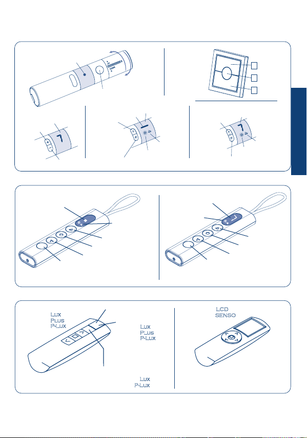
Compatible remote controls ................................................................................... p. 25
Key to symbols ....................................................................................................... p. 26
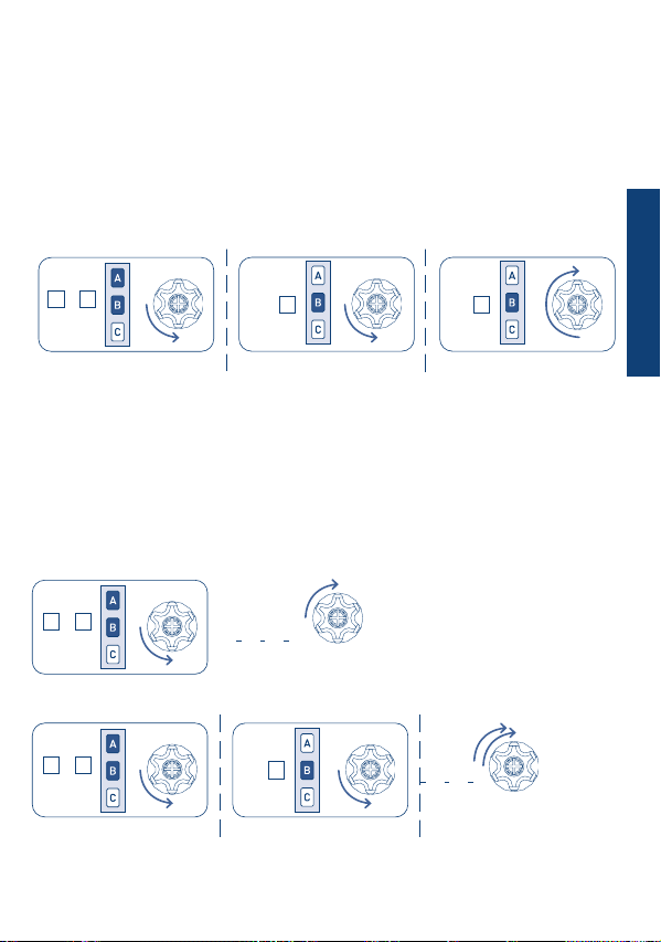
Command sequences example ............................................................................... p. 27
Function open/close programming remote control ............................................ p. 28-29
Setting the rst remote control............................................................................... p. 30
Automatic disabling of the rst remote control setting function ............................ p. 30
Setting the rotation direction of the motor ............................................................ p. 30
Setting of additional remote controls ..................................................................... p. 31
Remote control memory clearing ........................................................................... p. 31
Full memory clearing .............................................................................................. p. 31
Time-out setting ..................................................................................................... p. 32
Compatible devices:
Mistral .................................................................................................................... p. 33
Rugiada .................................................................................................................. p. 34
Anemometers ......................................................................................................... p. 34
Enable/disable the sun sensor (WindTec Lux) ......................................................... p. 35
Test mode (WindTec/WindTec Lux) ......................................................................... p. 35
Wind sensor WindTec SC ........................................................................................ p. 36
Switch..................................................................................................................... p. 37
Special functions: short-term setting of a remote control ....................................... p. 38
Technical features ................................................................................................... p. 93
EU Declaration of conformity ................................................................................. p. 94
21
ENGLISH

SAFETY INSTRUCTIONS
ELECTRICAL CONNECTIONS
- Only professional technicians must perform installation, complying with all safety
instructions, especially those regarding electrical connections.
- To avoid short circuits, arrange an automatic bipolar switch with opening distance of the
contacts of at least 3 mm before the circuit.
22
WINDTEC SC
COM
COM
RESET/AUX
ENGLISH

SKIPPER Series
MISTRAL
Ref. A520012 RUGIADA
Ref. A520016
GIRO Series
POP Series
WINDTEC - Ref.A520007
WINDTEC LUX - Ref.A520008
BROWN
BLACK
BLUE
YELLOW-GREEN
TDS GOLD - Ref.A510020
23
ENGLISH

WINDTEC SC
Ref. A520010
24
BROWN
BLACK
BLUE
YELLOW-GREEN
TDS GOLD - Ref.A510020
ENGLISH
SKIPPER Series
GIRO Series
POP Series

Up
Stop
Down
SEL (POP Lux)
Activating/ Deactivating
the Sun sensor
Up
Stop
Down
SEL (POP P-Lux)
Activating/ Deactivating
the Sun sensor
25
ENGLISH
COMPATIBLE REMOTE CONTROLS
LED DISPLAY
GIRO GIRO Wall
DISPLAY
Change
channel +
Change
channel -
up
stop
down
A
B
C
UP
DOWN
LED
STOP
GIRO Plus LED DISPLAY
GIRO Lux
Activating the
Sun sensor
Deactivating the Sun sensor
Sun sensor is “ON”
Wind sensor
is “ON”
GIRO P-Lux
DISPLAY
Change channel
Activating/ Deactivating the Sun sensor
Wind sensor
is “ON”
Sun sensor is “ON”
display -
Channel selector
LED -
Check the specic instruction
book
Skipper
Skipper
Skipper
Skipper
Skipper
Skipper
Skipper
Skipper
Skipper
Skipper
POP
POP Lux
Sun/wind sensor
(POP Lux)
POP Plus
POP P-Lux
Sun/wind sensor
(POP P-Lux)
Activating/ Deactivating the Sun sensor
Skipper
Skipper

ENGLISH
26
Down
Up
short motor rotation
in one direction
long motor rotation
in other direction
double short
rotation
GIRO
Skipper
POP
KEY TO SYMBOLS
Press button A
A
Press buttons A and B
at the same time
+
A B
down
stop
up
A
B
C
stop
up
A
B
Cdown
A
B
C
DOWN
UP
press the
DOWN button
on the switch
press the UP
button on the
switch
release the
button pressed
on the switch

27
COMMAND SEQUENCES EXAMPLE
Most of the command sequences have three distinct steps, at the end of which the motor
indicates if the step has been concluded positively or not, by turning in different ways.This
section is provided to demonstrate the motor indications. The buttons must be pressed as
shown in the sequence, without taking more than 4 seconds between one step and the
next. If more than 4 seconds are taken, the command is not accepted and the sequence
must be repeated.
Command sequence example:
As we can see from the example, when the sequence ends positively, the motor returns to
its starting position in one long rotation. In fact, two short rotations in the same direction
correspond to one long rotation in the opposite direction.The motor returns to the starting
position even when the sequence is not completed; in this case by performing one or two
short rotations.
Example of a wrong sequence:
ENGLISH
Step 1
Step 1
> 4 sec repeat the
sequence
repeat the
sequence
Step 2
> 4 sec
+
A B
+
A B B
Step 1 Step 3Step 2
+
A B B B

28
ENGLISH
FUNCTION OPEN/CLOSE PROGRAMMING
REMOTE CONTROL SKIPPER PLUS - SKIPPER LUX - SKIPPER P-LUX
REMOTE CONTROL POP PLUS - POP LUX - POP P-LUX
To prevent accidental changes to the programming of the motor during the daily use of
the remote control, the possibility of programming is disabled automatically 8 hours after
sending the last sequence (A+B or B+C).
CHECKING THE STATUS OF THE FUNCTION
To change the status of the function, see the sequences “ENABLE/DISABLE
PROGRAMMING”.
Proceed with programming as the instructions booklet.
ENABLE PROGRAMMING
DISABLE PROGRAMMING
Open
or after
30 sec.
Remove and replace
a battery
OPTION 2
OPTION 1
or after
30 sec.
Open
programming
Closed
programming
3 sec
or after
30 sec.
3 sec
Closed
3 sec
OPTION 2
+ +
A B C
Tn
+ +
A B C
Tn
+ +
A B C
Tn
B
B
B
C
A

29
ENGLISH
FUNCTION OPEN/CLOSE PROGRAMMING
REMOTE CONTROL SKIPPER - SERIES GIRO - REMOTE CONTROL POP
To prevent accidental changes to the programming of the motor during the daily use of
the remote control, the possibility of programming is disabled automatically 8 hours after
sending the last sequence (A+B or B+C).
CHECKING THE STATUS OF THE FUNCTION
To change the status of the function, see the sequences “ENABLE/DISABLE
PROGRAMMING”.
Proceed with programming as the instructions booklet.
ENABLE PROGRAMMING
DISABLE PROGRAMMING
ON
Open
programming
Closed
programming
....
ON
....
.... Closed
Open
ON
or after
30 sec.
or after
30 sec.
1 2 3
OPTION 1
1 2 3
1 2 3 or after
30 sec.
OPTION 2 OPTION 2
+ +
A B CB
B
C
+ +
A B C
+ +
A B C
A
B
Tn
Tn
Tn
Remove one battery and wait minimum 5 seconds or press any button.
2 sec
B
OPTION 2

SETTING THE FIRST REMOTE CONTROL
SETTING THE ROTATION DIRECTION OF THE MOTOR
This operation can only be performed when the control unit is new, or after a total delete
of the memory.
T1: First remote control to be set
This operation is mandatory if the rotation direction of the motor does not match to the
UP and DOWN functions of the remote control as an exemple if giving UP command the
awning descend.
The proper motor direction must be set, if the motor is linked to a Wind sensor. In case of
a wind alarm, the motor will always perform the command associated to the UP button.
Setting the rotation direction using the button RESET/AUX:
Interchanging the BROWN and BLACK motor wire on the terminals of the control unit,
will also reverse the rotation direction.
The control unit will keep this setting even after complete memory clearing!!
During this step, power up only one control unit at time!
30
max 2 sec
T1T1 T1 (2 sec)
Every time you connect the power supply to the control unit, you have 3 hours to
store the rst remote control. After this time, the ability to store the remote control is
disabled. To reset the timer of the function you have to disconnect and reconnect the
power supply to the control unit.
AUTOMATIC DISABLING OF THE FIRST
REMOTE CONTROL SETTING FUNCTION
ENGLISH
+
A B B B

SETTING OF ADDITIONAL REMOTE CONTROLS
REMOTE CONTROL MEMORY CLEARING
FULL MEMORY CLEARING
Up to 15 remote controls can be set, including the light/wind sensor and the rain sensor.
Tn: Already programmed remote control
Tx: Additional remote control
It is possible to delete each memorized remote control individually. As the last one
is deleted the control unit initial condition is restored. The same applies to the single
channels of a multichannel remote control: just select the channel to cancel.
Tn: Remote control to be cleared
The full memory clearing can be performed in two ways:
1) WITH THE REMOTE CONTROL
Tn: Already programmed remote control
31
2) WITH THE BUTTON RESET/AUX:
ENGLISH
TnTn Tx (2 sec)
+
A B BB
TnTn Tn (2 sec)
+
A B B
A
TnTn Tn (4 sec)
+
A B +
A B
B
(8 sec)

TIME-OUT SETTING
Time-out is the time during which the control unit is active, that’s to say an opening or
closing order is given. This time must always be longer than the opening-closing time of
the device being controlled.The time-out ends after pressing the STOP button or also after
the set value.
From factory setting: 90 seconds
32
The control unit will keep this setting even after
complete memory clearing!
ENGLISH
2 sec
180 s
45 s
90 s
+
B C
AA
C
B

33
COMPATIBLE DEVICES
I
For the complete description of the functions of this device see the instruction booklet
that came in the box.
It detects movements caused by the wind on the awning arms.
MISTRAL SENSOR
SETTING THE SENSOR
DELETING THE SENSOR
SELECTOR
LED
SET BUTTON
0
To associate the sensor to the control unit, a remote control must be already memorized.
Set the selector to the 0 position and then perform this sequence:
To delete the sensor from the control unit, an already programmed remote control must
be used. Set the
selector
to the 0 position; if active wait for the sensor to go off and then
perform this sequence:
MISTRAL- Ref. A520012
ENGLISH
2 sec
set
+
A B B
2 sec
set
+
A B
A

34
ANEMOMETERS
WINDTEC - Ref. A520007 WINDTEC LUX - Ref. A520008
Sun-sensor
tuning
Set button
Wind-speed
tuning
set
SETTING
To associate the sensor to the control unit, a remote control must be already memorised.
The setting sequence is the following:
DELETING
To delete the sensor from the control unit, an already programmed remote control must
be used. The deleting sequence is the following:
For the complete description of the functions of these devices see the instruction booklet
that came in the box.
RUGIADA (TX RAIN-SENSOR)
Power Supply 230 Vac
Sensor element
Set button
set
Rugiada - Ref. A520016
ENGLISH
2 sec
set
+
A B B
2 sec
set
+
A B
A

TEST MODE (WINDTEC/WINDTEC LUX)
This function is useful to check proper radio communications and to perform the wind
and sun function test.
To activate the TEST function, hold the SET button down for around 2 seconds, until
the awning opens for 10 seconds and closes briey to conrm that the test has been
activated. The Test function lasts for 3 minutes, during which the wind and sunlight
threshold settings can be checked, without waiting for activation times. After 3 minutes,
the WindTec sensor returns to normal operational mode. During the wind-alarm the red
led inside the control unit is on.
WIND FUNCTION TEST (WINDTEC, WINDTEC LUX)
To avoid errors during the wind function test, it is suggested that the sunlight function
be deactivated. By spinning the anemometer ns, when the speed detected by the sensor
exceeds the threshold set, the motor commands the closing of the awnings.
SUN FUNCTION TEST (WINDTEC LUX)
Make sure that the sunlight function is on. When the sensor detects a change in the
sunlight intensity, it opens the awning if the sunlight intensity goes above the threshold
set, or it closes the awning if the light intensity goes below the threshold set. It is possible
to repeat this test several times, so as to nd the desired adjustment levels precisely.
35
2 sec
set
ENGLISH
ENABLE / DISABLE THE SUN SENSOR
(WindTec Lux)
To enable (automatically) or disable (manually) the sun sensor refer to the instruction
manual provided with the sensor or the remote control you want to use.

WIND SENSOR WINDTEC SC
This kind of Wind-sensor must be wired to the control unit on the indicated terminals,
without respecting the polarity. Exceeding the set level the control unit will automatically
perform the command associated to UP ward function of the remote control. So check
that the rotation direction will correctly match this function. If not it’s absolutely
necessary to set the rotation direction.The “Wind-alarm” time is 8 minutes during which
the control unit will not accept any command. During the wind-alarm the red led inside
the control unit blinks.
WIND-SPEED SETTING (WINDTEC SC)
In factory set on: 25 km/h
The control unit will keep the wind-speed setting
even after complete memory clearing!!
36
ENGLISH
WARNING:
do not connect more than 5
control units to one anemometer
WindTec SC.
WINDTEC SC - Ref.A520010
2 sec
25 km/h
15 km/h
35 km/h
+
B C
A
C
B
B

TEST FOR WIND-SENSOR (WINDTEC SC)
This function is useful to check the correct connection to the control unit and the rotation
direction in case of wind-alarm.
Activate the TEST function, with the sequence B+C, C. The awning opens for 10 seconds
and closes briey to conrm that the test mode is activated. Move the anemometer
blades by hand, the motor performs short moves in closing direction. If the direction is
not right it’s necessary to invert the rotation direction. To quit the test mode press any
button from the remote control. During the wind-alarm the red led inside the control
unit is on.
37
SWITCH
It is possible to run the motor through a switch connected to the control unit with three
wires (up, down and common).
The switch must be equipped with mechanical or electrical interlock, to prevent
two commands being sent simultaneously. Furthermore, the switch must be an
unstable pushbutton: releasing it, the switch opens.
ENGLISH
+
B C
C

38
Pressing one of the two buttons and releasing,
the motor drives to the desired direction until it reaches
the limits.
STOP
OPERATION
To stop the motor
before reaching the
limits press again the
same button.
If during the movement
the other button is
pressed the motor
changes the direction.
SPECIAL FUNCTIONS
SHORT-TERM SETTING OF A REMOTE CONTROL
This function makes it possible to store a remote control temporarily, for example, with
the purpose of setting the limit switches during assembly in the factory. A later nal
saving of the remote control will be possible using the appropriate command sequence
(see: “SETTING THE FIRST REMOTE CONTROL”). The operations described below can be
carried out only when the control unit has just come out of the factory or after a full
memory clearing (see: “FULL MEMORY CLEARING”).The control unit makes the following
operations possible only within the time limits described in order to make sure that the
short-term setting is used only in the installation or factory setting phase and not during
daily use. Power up the control unit, make sure that no other control units having an
empty memory are powered up in the same operating range.
Within 30 seconds after start, press the B and C buttons simultaneously until the motor
gives a conrmation signal.
The remote control will remain stored for 5 minutes, while the control unit is
powered up. After 5 minutes or when the control unit has its power cut off, the remote
control will be cancelled.
T1: First remote control to be stored
ENGLISH
T1
+
BC
+
B C
This manual suits for next models
1
Table of contents
Other CHERUBINI Control Unit manuals
Popular Control Unit manuals by other brands

Pentair
Pentair FLECK 2850 SXT user guide

Thitronik
Thitronik Pro-finder Operating and installation instructions

Bauerfeind
Bauerfeind Uniprox V08 instruction manual

Concoa
Concoa 830-9412 Installation and operation instruction

DeDietrich
DeDietrich JA7 Assembly instructions

STI
STI CM Series operating instructions