manuals.online logo
Brands
  1. Home
  2. •
  3. Brands
  4. •
  5. LOVATO ELECTRIC
  6. •
  7. Control Unit
  8. •
  9. LOVATO ELECTRIC EXP10 13 User manual

LOVATO ELECTRIC EXP10 13 User manual

I296 I GB F E 04 16 31100134
1
LOVATO ELECTRIC S.P.A.
24020 GORLE (BERGAMO) ITALIA
VIA DON E. MAZZA, 12
TEL. 035 4282111
FAX (Nazionale): 035 4282200
FAX (International): +39 035 4282400
E-mail info@LovatoElectric.com
Web www.LovatoElectric.com
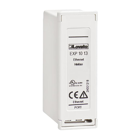
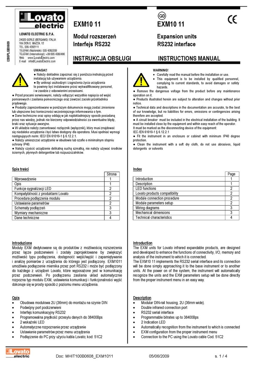
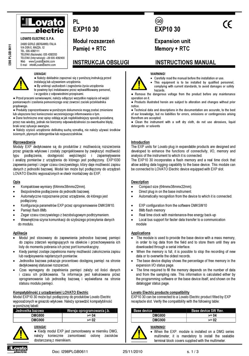
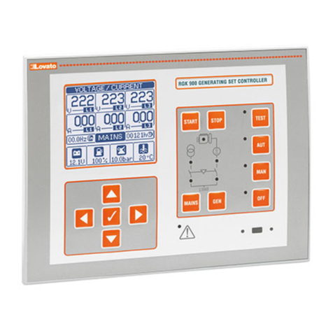
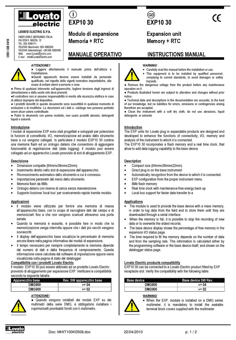
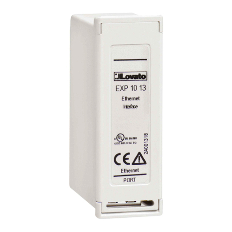
EXP10 13
I MODULO DI ESPANSIONE - INTERFACCIA ETHERNET ISOLATA
GB EXPANSION MODULE - OPTO-ISOLATED ETHERNET INTERFACE
F MODULE D’EXTENSION - INTERFACE ETHERNET ISOLEE
E MÓDULO DE EXPANSIÓN - INTERFAZ ETHERNET AISLADA
WARNING!
– Carefully read the manual before the installation or use.
– This equipment is to be installed by qualified personnel, complying to current standards, to avoid
damages or safety hazards.
– Before any maintenance operation on the device, remove all the voltages from measuring and supply inputs and short-
circuit the CT input terminals.
– The manufacturer cannot be held responsible for electrical safety in case of improper use of the equipment.
– Products illustrated herein are subject to alteration and changes without prior notice. Technical data and descriptions
in the documentation are accurate, to the best of our knowledge, but no liabilities for errors, omissions or
contingencies arising there from are accepted.
– A circuit breaker must be included in the electrical installation of the building. It must be installed close by the
equipment and within easy reach of the operator. It must be marked as the disconnecting device of the equipment:
IEC /EN 61010-1 § 6.11.2.
– Clean the device with a soft dry cloth; do not use abrasives, liquid detergents or solvents.
ATTENZIONE!
– Leggere attentamente il manuale prima dell’utilizzo e l’installazione.
– Questi apparecchi devono essere installati da personale qualificato, nel rispetto delle vigenti normative
impiantistiche, allo scopo di evitare danni a persone o cose.
– Prima di qualsiasi intervento sullo strumento, togliere tensione dagli ingressi di misura e di alimentazione e
cortocircuitare i trasformatori di corrente.
– Il costruttore non si assume responsabilità in merito alla sicurezza elettrica in caso di utilizzo improprio del dispositivo.
– I prodotti descritti in questo documento sono suscettibili in qualsiasi momento di evoluzioni o di modifiche. Le
descrizioni ed i dati a catalogo non possono pertanto avere alcun valore contrattuale.
– Un interruttore o disgiuntore va compreso nell’impianto elettrico dell’edificio. Esso deve trovarsi in stretta vicinanza
dell’apparecchio ed essere facilmente raggiungibile da parte dell’operatore. Deve essere marchiato come il dispositivo
di interruzione dell’apparecchio: IEC/ EN 61010-1 § 6.11.2.
– Pulire l’apparecchio con panno morbido, non usare prodotti abrasivi, detergenti liquidi o solventi.
ATTENTION !
– Lire attentivement le manuel avant toute utilisation et installation.
– Ces appareils doivent être installés par un personnel qualifié, conformément aux normes en vigueur en
matière d'installations, afin d'éviter de causer des dommages à des personnes ou choses.
– Avant toute intervention sur l'instrument, mettre les entrées de mesure et d'alimentation hors tension et court-circuiter
les transformateurs de courant.
– Le constructeur n'assume aucune responsabilité quant à la sécurité électrique en cas d'utilisation impropre du
dispositif.
– Les produits décrits dans ce document sont susceptibles d'évoluer ou de subir des modifications à n'importe quel
moment. Les descriptions et caractéristiques techniques du catalogue ne peuvent donc avoir aucune valeur
contractuelle.
– Un interrupteur ou disjoncteur doit être inclus dans l'installation électrique du bâtiment. Celui-ci doit se trouver tout
près de l'appareil et l'opérateur doit pouvoir y accéder facilement. Il doit être marqué comme le dispositif
d'interruption de l'appareil : IEC/ EN 61010-1 § 6.11.2.
– Nettoyer l’appareil avec un chiffon doux, ne pas utiliser de produits abrasifs, détergents liquides ou solvants.
UWAGA!
– Przed użyciem i instalacją urządzenia należy uważnie przeczytać niniejszą instrukcję.
– W celu uniknięcia obrażeń osób lub uszkodzenia mienia tego typu urządzenia muszą być instalowane przez
wykwalifikowany personel, zgodnie z obowiązującymi przepisami.
– Przed rozpoczęciem jakichkolwiek prac na urządzeniu należy odłączyć napięcie od wejść pomiarowych i zasilania oraz zewrzeć
zaciski przekładnika prądowego.
– Producent nie przyjmuje na siebie odpowiedzialności za bezpieczeństwo elektryczne w przypadku niewłaściwego użytkowania
urządzenia.
– Produkty opisane w niniejszym dokumencie mogą być w każdej chwili udoskonalone lub zmodyfikowane. Opisy oraz dane
katalogowe nie mogą mieć w związku z tym żadnej wartości umownej.
– W instalacji elektrycznej budynku należy uwzględnić przełącznik lub wyłącznik automatyczny. Powinien on znajdować się w
bliskim sąsiedztwie urządzenia i być łatwo osiągalny przez operatora. Musi być oznaczony jako urządzenie służące do
wyłączania urządzenia: IEC/ EN 61010-1 § 6.11.2.
– Urządzenie należy czyścić miękką szmatką, nie stosować środkow ściernych, płynnych detergentow lub rozpuszczalnikow.
ACHTUNG!
– Dieses Handbuch vor Gebrauch und Installation aufmerksam lesen.
– Zur Vermeidung von Personen- und Sachschäden dürfen diese Geräte nur von qualifiziertem
Fachpersonal und unter Befolgung der einschlägigen Vorschriften installiert werden.
– Vor jedem Eingriff am Instrument die Spannungszufuhr zu den Messeingängen trennen und die Stromwandler
kurzschlieβen.
– Bei zweckwidrigem Gebrauch der Vorrichtung übernimmt der Hersteller keine Haftung für die elektrische Sicherheit.
– Die in dieser Broschüre beschriebenen Produkte können jederzeit weiterentwickelt und geändert werden. Die im
Katalog enthaltenen Beschreibungen und Daten sind daher unverbindlich und ohne Gewähr.
– In die elektrische Anlage des Gebäudes ist ein Ausschalter oder Trennschalter einzubauen. Dieser muss sich in
unmittelbarer Nähe des Geräts befinden und vom Bediener leicht zugänglich sein. Er muss als Trennvorrichtung für das
Gerät gekennzeichnet sein: IEC/ EN 61010-1 § 6.11.2.
– Das Gerät mit einem weichen Tuch reinigen, keine Scheuermittel, Flüssigreiniger oder Lösungsmittel verwenden.
ADVERTENCIA
– Leer atentamente el manual antes de instalar y utilizar el regulador.
– Este dispositivo debe ser instalado por personal cualificado conforme a la normativa de instalación
vigente a fin de evitar daños personales o materiales.
– Antes de realizar cualquier operación en el dispositivo, desconectar la corriente de las entradas de alimentación y
medida, y cortocircuitar los transformadores de corriente.
– El fabricante no se responsabilizará de la seguridad eléctrica en caso de que el dispositivo no se utilice de forma
adecuada.
– Los productos descritos en este documento se pueden actualizar o modificar en cualquier momento. Por consiguiente,
las descripciones y los datos técnicos aquí contenidos no tienen valor contractual.
– La instalación eléctrica del edificio debe disponer de un interruptor o disyuntor. Éste debe encontrarse cerca del
dispositivo, en un lugar al que el usuario pueda acceder con facilidad. Además, debe llevar el mismo marcado que el
interruptor del dispositivo (IEC/ EN 61010-1 § 6.11.2).
– Limpiar el dispositivo con un trapo suave; no utilizar productos abrasivos, detergentes líquidos ni disolventes.
ПРЕДУПРЕЖДЕНИЕ!
– Прежде чем приступать к монтажу или эксплуатации устройства, внимательно ознакомьтесь с одержанием
настоящего руководства.
– Во избежание травм или материального ущерба монтаж должен существляться только квалифицированным персоналом
в соответствии с действующими нормативами.
– Перед проведением любых работ по техническому обслуживанию устройства необходимо обесточить все
измерительные и питающие входные контакты, а также замкнуть накоротко входные контакты трансформатора тока (ТТ).
– Производитель не несет ответственность за обеспечение электробезопасности в случае ненадлежащего использования
устройства.
– Изделия, описанные в настоящем документе, в любой момент могут подвергнуться изменениям или
усовершенствованиям. Поэтому каталожные данные и описания не могут рассматриваться как действительные с точки
зрения контрактов
– Электрическая сеть здания должна быть оснащена автоматическим выключателем, который должен быть расположен
вблизи оборудования в пределах доступа оператора. Автоматический выключатель должен быть промаркирован как
отключающее устройство оборудования: IEC /EN 61010-1 § 6.11.2.
– Очистку устройства производить с помощью мягкой сухой ткани, без применения абразивных материалов, жидких
моющих средств или растворителей.
UPOZORNĚNÍ
– Návod se pozorně pročtěte, než začnete regulátor instalovat a používat.
– Tato zařízení smí instalovat kvalifikovaní pracovníci v souladu s platnými předpisy a normami pro předcházení
úrazů osob či poškození věcí.
– Před jakýmkoli zásahem do přístroje odpojte měřicí a napájecí vstupy od napětí a zkratujte transformátory proudu.
– Výrobce nenese odpovědnost za elektrickou bezpečnost v případě nevhodného používání regulátoru.
– Výrobky popsané v tomto dokumentu mohou kdykoli projít úpravami či dalším vývojem. Popisy a údaje uvedené v katalogu
nemají proto žádnou smluvní hodnotu.
– Spínač či odpojovač je nutno zabudovat do elektrického rozvodu v budově. Musejí být nainstalované v těsné blízkosti přístroje a
snadno dostupné pracovníku obsluhy. Je nutno ho označit jako vypínací zařízení přístroje: IEC/ EN 61010-1 § 6.11.2.
– Přístroj čistěte měkkou utěrkou, nepoužívejte abrazivní produkty, tekutá čistidla či rozpouštědla.
DİKKAT!
– Montaj ve kullanımdan önce bu el kitabını dikkatlice okuyunuz.
– Bu aparatlar kişilere veya nesnelere zarar verme ihtimaline karşı yürürlükte olan sistem kurma normlarına göre
kalifiye personel tarafından monte edilmelidirler
– Aparata (cihaz) herhangi bir müdahalede bulunmadan önce ölçüm girişlerindeki gerilimi kesip akım transformatörlerinede kısa
devre yaptırınız.
– Üretici aparatın hatalı kullanımından kaynaklanan elektriksel güvenliğe ait sorumluluk kabul etmez.
– Bu dokümanda tarif edilen ürünler her an evrimlere veya değişimlere açıktır. Bu sebeple katalogdaki tarif ve değerler herhangi bir
bağlayıcı değeri haiz değildir.
– Binanın elektrik sisteminde bir anahtar veya şalter bulunmalıdır. Bu anahtar veya şalter operatörün kolaylıkla ulaşabileceği yakın
bir yerde olmalıdır. Aparatı (cihaz) devreden çıkartma görevi yapan bu anahtar veya şalterin markası: IEC/ EN 61010-1 § 6.11.2.
– Aparatı (cihaz) sıvı deterjan veya solvent kullanarak yumuşak bir bez ile siliniz aşındırıcı temizlik ürünleri kullanmayınız.
AVERTIZARE!
– Citiţi cu atenţie manualul înainte de instalare sau utilizare.
– Acest echipament va fi instalat de personal calificat, în conformitate cu standardele actuale, pentru a evita
deteriorări sau pericolele.
– Înainte de efectuarea oricărei operaţiuni de întreţinere asupra dispozitivului, îndepărtaţi toate tensiunile de la intrările de
măsurare şi de alimentare şi scurtcircuitaţi bornele de intrare CT.
– Producătorul nu poate fi considerat responsabil pentru siguranţa electrică în caz de utilizare incorectă a echipamentului.
– Produsele ilustrate în prezentul sunt supuse modificărilor şi schimbărilor fără notificare anterioară. Datele tehnice şi descrierile
din documentaţie sunt precise, în măsura cunoştinţelor noastre, dar nu se acceptă nicio răspundere pentru erorile, omiterile sau
evenimentele neprevăzute care apar ca urmare a acestora.
– Trebuie inclus un disjunctor în instalaţia electrică a clădirii. Acesta trebuie instalat aproape de echipament şi într-o zonă uşor
accesibilă operatorului. Acesta trebuie marcat ca fiind dispozitivul de deconectare al echipamentului: IEC/EN 61010-1 § 6.11.2.
– Curăţaţi instrumentul cu un material textil moale şi uscat; nu utilizaţi substanţe abrazive, detergenţi lichizi sau solvenţi.
I296 I GB F E 04 16 31100134
2
COMPATIBILITÀ CON I PRODOTTI LOVATO
Il modulo EXP10 13 può essere abbinato ad
un prodotto Lovato Electric provvisto di
alloggiamento per espansione EXP...
Verificare la compatibilità secondo la
seguente tabella:
Apparecchio Rev. SW
base apparecchio base
DMG600/610 ≥00
DMG700/800... ≥01
DMG900/900T... ≥00
RGK800/900... - ≥00
RGK800/900SA -
RGK900MC
PMVF30... ≥00
PMVF20... ≥00
DCRG8/DCRL8 ≥00
ATL610/800/900 ≥00
ATTENZIONE!
Quando vengono installati i moduli EXP... nei
multimetri della serie DMG, è obbligatorio
montare i coprimorsetti piombabili forniti con il
multimetro.
LOVATO PRODUCTS COMPATIBILITY
EXP10 13 can be connected to a Lovato
Electric product fitted by EXP... receptacle
slot.
Verify the compatibility with the following
table:
Base Base device
device firmware Rev.
DMG600/610 ≥00
DMG700/800... ≥01
DMG900/900T... ≥00
RGK800/900... - ≥00
RGK800/900SA -
RGK900MC
PMVF30... ≥00
PMVF20... ≥00
DCRG8/DCRL8 ≥00
ATL610/800/900 ≥00
WARNING!
When the EXP... module is installed on a DMG
series multimeter, it is mandatory to install the
sealable terminal block covers supplied with the
multimeter.
COMPATIBILITE AVEC PRODUITS LOVATO
Le module EXP10 13 peut être associé à un
produit Lovato Electric pourvu de logements
d’extension EXP...
Vérifiez la compatibilité selon le tableau
suivant :
Appareil Rév. logicielle
de base appareil de base
DMG600/610 ≥00
DMG700/800... ≥01
DMG900/900T... ≥00
RGK800/900... - ≥00
RGK800/900SA -
RGK900MC
PMVF30... ≥00
PMVF20... ≥00
DCRG8/DCRL8 ≥00
ATL610/800/900 ≥00
ATTENTION !
Quand vous installez les modules EXP... dans
les multimètres de la série DMG, vous devez
obligatoirement monter les cache-bornes
plombables fournis avec le multimètre.
COMPATIBILIDAD CON LOS PRODUCTOS
LOVATO
El módulo EXP10 13 puede conectarse a
otros productos Lovato Electric provistos de
ranura de explansión para EXP... Verificar la
compatibilidad mediante la siguiente tabla:
Aparato Rev. firmware
principal aparato principal
DMG600/610 ≥00
DMG700/800... ≥01
DMG900/900T... ≥00
RGK800/900... - ≥00
RGK800/900SA -
RGK900MC
PMVF30... ≥00
PMVF20... ≥00
DCRG8/DCRL8 ≥00
ATL610/800/900 ≥00
¡ATENCIÓN!
Cuando se instalan módulos EXP... en los
multímetros de la serie DMG, es imprescindible
colocar los cubrebornes precintables que se
entregan con el multímetro.
PROCEDURA DI CONNESSIONE DEL MODULO MODULE CONNECTION PROCEDURE PROCEDURE DE CONNEXION DU MODULE PROCEDIMIENTO DE CONEXIÓN DEL MÓDULO
CLICK!
1234
A1 A2 B1 B2
1. Rimuovere le tensioni pericolose.
2. Rimuovere i coprimorsetti e la morsettiera
estraibile.
3. Rimuovere il tappo di copertura dello slot nel
quale si intende inserire il modulo .
4. Inserire l’EXP10 13 come illustrato in alto.
5. Riposizionare la morsettiera estraibile e
montare i coprimorsetti.
6. Alimentare l’apparecchio principale (verrà
riconosciuto il nuovo modulo di espansione).
NOTA: per togliere il modulo, rimuovere ogni
tensione pericolosa e ripetere in senso contrario le
operazioni dal punto 5 al punto 2. Premere nel
punto indicato con per sganciare il modulo.
1. Remove any dangerous voltage.
2. Remove terminal covers and terminal block.
3. Remove the expansion slot cover of the Lovato
product at the position in which the EXP will
be plugged in.
4. Insert the EXP10 13 as illustrated in above.
5. Reinstall the terminal block and the terminal
cover.
6. Power up the system (the base device will
automatically recognise the expansion unit).
NOTE: Remove any dangerous voltage and repeat
the operations from step 5 to step 2 in reverse
order. Press in the point indicated by the above
in order to remove the module.
1. Coupez les tensions dangereuses.
2. Retirez les cache-bornes et le bornier
extractible.
3. Enlevez le bouchon du logement où on vent
insérer le module.
4. Insérez l’EXP10 13 comme illustré ci-dessus.
5. Remettez en place le bornier extractible et les
cache-bornes.
6. Mettez l’appareil principal sous tension (le
nouveau module d’extension est
automatiquement reconnu).
NOTA : pour retirer le module, coupez les tensions
dangereuses et répétez les opérations du point 5
au point 2 dans le sens inverse. Pour décrocher le
module, enfoncez la patte indiquée par .
1. Desconectar las tensiones peligrosas.
2. Retirar los cubrebornes y la clema extraíble.
3. Retirar la tapa de la ranura de expansión en la
que se desee conectar el módulo.
4. Introducir el módulo EXP10 13 como se ilustra
en la figura superior.
5. Colocar nuevamente la clema extraíble y los
cubrebornes.
6. Conectar el aparato principal a la alimentación
(reconocerá el nuevo módulo de expansión).
NOTA: Para extraer el módulo, desconectar la
tensión y repetir al contrario las operaciones desde
el punto 5 hasta el punto 2. Pulsar en el punto
indicado con para desenganchar el módulo.
INTRODUZIONE
I moduli di espansione EXP... sono stati
progettati e sviluppati per potenziare le
funzioni di connettività, I/O, memorizzazione
ed analisi dell’apparecchio base a cui
vengono collegati.
Il modulo EXP10 13 realizza la funzione di
interfaccia isolata di tipo ETHERNET. Questo
modulo può essere collegato ad un
apparecchio LOVATO Electric provvisto di
slot per EXP. La connessione avverrà
semplicemente inserendo il modulo di
espansione nello strumento principale il
quale ne effettuerà automaticamente il
riconoscimento. L’impostazione dei parametri
del modulo viene svolta in modo intuitivo e
semplice nel menù di configurazione
presente nel dispositivo principale.
DESCRIZIONE
– Dimensioni compatte.
– Inserimento diretto nello slot di
espansione dell’apparecchio.
– Interfaccia di comunicazione ETHERNET
isolata (2kVrms per 1 minuto
dall’apparecchio base).
– Interfaccia di comunicazione ETHERNET
10/100Mbps.
– Protocollo TCP/IP.
– 2 LED bi-colore sul connettore RJ45 per
lo stato della connessione ETHERNET.
INTRODUCTION
EXP... expansion modules are designed and
developed to enhance the functions of
connectivity, I/O, memory and analysis of
the device to which it is connected.
The EXP10 13 implements the isolated
ETHERNET interface. This module can be
connected to a LOVATO Electric device
equipped with EXP slot.
The module connection is done simply by
plugging it in to the expansion slot of the
base device which will automatically
recognise it. The EXP parameter setup is
done directly from the base device menu in
an easy way.
DESCRIPTION
– Compact size
– Direct plug in on the base device
– Isolated ETHERNET communication
interface (2kVrms for 1 minute with base
device)
– 10/100 Mbps ETHERNET communication
– TCP/IP protocol
– 2 status dual-colour LEDs on the RJ45
connector for ETHERNET status.
INTRODUCTION
Les modules d’extension ont été conçus et
développés pour améliorer les fonctions de
connectivité, E/S, mémorisation et analyse
de l’appareil de base auquel ils sont
branchés. Le module EXP10 13 réalise la
fonction d’interface isolée de type
ETHERNET. Ce module peut être branché à
un appareil LOVATO Electric pourvu
d’emplacements EXP. La connexion a lieu en
insérant simplement le module d’extension
dans l’appareil principal qui le reconnaîtra
automatiquement.
La définition des paramètres du module se
fait d’une manière intuitive et simple dans le
menu de configuration de l’appareil
principal.
DESCRIPTION
– Dimensions compactes.
– Insertion directe dans le logement
d’extension de l’appareil.
– Interface de communication ETHERNET
isolée (2kVrms pendant 1 minute vers
l’appareil de base).
– Interface de communication ETHERNET
10/100 Mbps.
– Protocole TCP/IP.
– 2 DELs bicolores sur le connecteur RJ45
pour l’état de la connexion ETHERNET.
INTRODUCCIÓN
Los módulos de expansión EXP... han sido
proyectados y desarrollados a fin de
potenciar las funciones de conectividad, I/O,
memorización y análisis del aparato principal
al que se conecten. En particular, el módulo
EXP10 13 cumple la función de puerto
aislado de tipo ETHERNET. Este módulo
puede conectarse a otros productos LOVATO
Electric provistos de ranura de expansión
para EXP. Para la conexión es suficiente
introducir el módulo de expansión en el
aparato principal para que el mismo efectúe
automáticamente el reconocimiento.
La configuración de los parámetros del
módulo se realiza de manera simple e
intuitiva mediante el menú de configuración
presente en el aparato principal.
DESCRIPCIÓN
– Dimensiones compactas.
– Entrada directa en la ranura de expansión
del aparato.
– Interfaz de comunicación ETHERNET
dislado (2kVrms durante 1 minuto del
aparato principal).
– Interfaz de comunicación ETHERNET
10/100Mbps.
– Protocolo TCP/IP.
– 2 LEDs bicolor en el conector RJ45 para
señalar el estado de la conexión
ETHERNET.
I296 I GB F E 04 16 31100134
3
DIMENSIONI MECCANICHE [mm] MECHANICAL DIMENSIONS [mm] DIMENSIONS MECANIQUES [mm] DIMENSIONES MECÁNICAS [mm]
64.5
38.2
22.0
46.8
CARATTERISTICHE TECNICHE
Alimentazione
Tensione alimentazione 5V (fornita dall’apparecchio base)
Corrente assorbita 250mA
Potenza assorbita/dissipata 1,25W
Interfaccia ETHERNET
Interfaccia di rete RJ45 Ethernet 10BASE-T oppure 100BASE-TX
(auto-sensing)
Compatibilità Versione 2.0/IEEE802.3
Connessione porta ETHERNET
Tipo di connettore RJ45
Connessione al prodotto base
Tipo di connettore Ad innesto
Isolamento
Tensione nominale di tenuta a impulso Uimp 4kV
Tensione di tenuta a frequenza d’esercizio 2kV
Condizioni ambientali
Temperatura di impiego -20...+60°C
Temperatura di stoccaggio -30...+80°C
Umidità relativa <80% (IEC/EN 60068-2-70)
Grado di inquinamento ambiente massimo 2
Categoria dì sovratensione 3
Altitudine ≤2000m
Sequenza climatica Z/ABDM (IEC/EN 60068-2-61)
Resistenza agli urti 15g (IEC/EN 60068-2-27)
Resistenza alle vibrazioni 0,7g (IEC/EN 60068-2-6)
Contenitore
Montaggio Ad inserimento nello slot di espansione plug in
Materiale Poliammide RAL 7035
Grado di protezione IP20
Peso 60g
Omologazioni e conformità
Omologazioni ottenute cULus, EAC
Conformi alle norme IEC/EN 61010-1, IEC/EN 61000-6-2
IEC/EN 61000-6-3, UL508, CSA C22.2 n°14
I
TECHNICAL CHARACTERISTICS
Supply
Supply voltage 5V (supplied by base device)
Supply current 250mA
Power consumption/dissipation 1.25W
ETHERNET interface
Network Interface RJ45 Ethernet 10BASE-T or 100BASE-TX
(auto-sensing)
Compatibility Version 2.0/IEEE802.3
ETHERNET port connection
Type of connector type RJ45
Base device connection
Type of connector Plug-in
Insulation
Rated impulse withstand voltage Uimp 4kV
Power frequency withstand voltage 2kV
Ambient conditions
Operating temperature -20...+60°C
Storage temperature -30...+80°C
Relative humidity <80% (IEC/EN 60068-2-70)
Maximum pollution degree 2
Overvoltage category 3
Altitude ≤2000m
Climatic sequence Z/ABDM (IEC/EN 60068-2-61)
Shock resistance 15g (IEC/EN 60068-2-27)
Vibration resistance 0.7g (IEC/EN 60068-2-6)
Housing
Mounting In the plug in expansion slot
Material Polyamide RAL7035
Degree of protection IP20
Weight 60g
Certifications and compliance
Certifications obtained cULus, EAC
Comly with standards IEC/EN 61010-1, IEC/EN 61000-6-2
IEC/EN 61000-6-3, UL508, CSA C22.2 n°14
GB
FUNZIONE DEI LED SUL CONNETTORE RJ45
ETHERNET
POSIZIONE COLORE DESCRIZIONE
LED SINISTRO Spento Nessuna
(connessione) connessione
Verde 100Mbps
Ambra 10Mbps
LED DESTRO Spento Nessuna attività
(attività)
Verde Full Duplex
Ambra Half Duplex
PROGRAMMAZIONE PARAMETRI
Per la programmazione dei parametri di
configurazione del modulo si rimanda al manuale
dello strumento principale a cui lo si intende
collegare.
Rivolgersi ad un amministratore di rete per
l’assegnazione dei parametri di connessione al
modulo Ethernet.
RJ45 CONNECTOR ETHERNET LED FUNCTIONS
POSITION COLOUR DESCRIPTION
LEFT LED OFF No link
(Link)
Green 100Mbps
Amber 10Mbps
RIGHT LED OFF No activity
(Activity)
Green Full Duplex
Amber Half Duplex
MODULE PARAMETERS SETUP
To configure the module parameters, see the
manual of the base device with which it will be
installed.
Refer to network administrator for the Ethernet
module parameters allocation.
FONCTION DES DELS SUR LE CONNECTEUR
RJ45 ETHERNET
POSITION
COULEUR
DESCRIPTION
DEL GAUCHE Eteinte Pas de connexion
(connexion)
Verte 100Mbps
Ambre 10Mbps
DEL DROITE Eteinte Pas d’activité
(activité)
Verte Full Duplex
Ambre Half Duplex
PROGRAMMATION DES PARAMETRES
Pour programmer les paramètres du module,
reportez-vous au manuel de l’appareil principal
auquel il sera relié.
Adressez-vous à un administrateur de réseau
pour l’attribution des paramètres de connexion au
module Ethernet.
FUNCIÓN DE LOS LEDS EN EL CONECTOR RJ45
ETHERNET
POSICIÓN COLOR DESCRIPCIÓN
LED IZQUIERDO Apagado Ninguna
(conexión) conexión
Verde 100Mbps
Ámbar 10Mbps
LED DERECHO Apagado Ninguna actividad
(actividad)
Verde Full Duplex
Ámbar Half Duplex
PROGRAMACIÓN PARÁMETROS
Para la configuración de los parámetros del
módulo se remite al manual del equipo principal
al que se va a conectar.
Recurrir al administrador de red para la
asignación de los parámetros de conexión al
módulo Ethernet
I296 I GB F E 04 16 31100134
4
CARACTERISTIQUES TECHNIQUES
Alimentation
Tension d’alimentation 5V (fournie par l’appareil de base)
Consommation courant 250mA
Consommation puissance 1,25W
Interface ETHERNET
Interface réseau RJ45 Ethernet 10BASE-T ou 100BASE-TX
(auto-sensing)
Compatibilité Version 2.0/IEEE802.3
Connexion port ETHERNET
Type de connecteur RJ45
Connexion à l’appareil de base
Type de connecteur A enclenchement
Isolation
Tension assignée de tenue aux chocs Uimp 4kV
Tension de tenue à fréquence de service 2kV
Environnement
Température de fonctionnement -20...+60°C
Température de stockage -30...+80°C
Humidité relative <80% (IEC/EN 60068-2-70)
Degré de pollution maximum 2
Catégorie de surtension 3
Altitude ≤2000m
Séquence climatique Z/ABDM (IEC/EN 60068-2-61)
Résistance aux chocs 15g (IEC/EN 60068-2-27)
Résistance aux vibrations 0,7g (IEC/EN 60068-2-6)
Boîtier
Montage Au logement d’extension embrochable
Matière Polyamide RAL7035
Degré de protection IP20
Masse 60g
Certifications et conformité
Certifications obtenues cULus, EAC
Conformes aux normes IEC/EN 61010-1, IEC/EN 61000-6-2
IEC/EN 61000-6-3, UL508, CSA C22.2 n°14
F
CARACTERÍSTICAS TÉCNICAS
Alimentación
Tensión alimentación 5V (suministrada por el aparato principal)
Corriente absorbida 250mA
Potencia absorbida/disipada 1,25W
Interfaz Ethernet
Interfaz de red RJ45 Ethernet 10BASE-T o 100BASE-TX
(auto-sensing)
Compatibilidad Versión 2.0/IEEE802.3
Conexión puerto ETHERNET
Tipo de conector RJ45
Conexión al aparato principal
Tipo de conector A presión
Aislamiento
Tensión soportada de impulso Uimp 4kV
Tensión soportada a frecuencia industrial 2kV
Condiciones ambientales
Temperatura de funcionamiento -20...+60°C
Temperatura de almacenamiento -30...+80°C
Humedad relativa <80% (IEC/EN 60068-2-70)
Grado de contaminación ambiental máxima 2
Categoría de sobretensión 3
Altitud ≤2000m
Secuencia climática Z/ABDM (IEC/EN 60068-2-61)
Resistencia a los golpes 15g (IEC/EN 60068-2-27)
Resistencia a las vibraciones 0,7g (IEC/EN 60068-2-6)
Caja
Montaje En la ranura de expansión del aparato
Material Poliamida RAL 7035
Grado de protección IP20
Peso 60g
Homologaciones y conformidad
Homologaciones obtenidas cULus, EAC
Conforme a normas IEC/EN 61010-1, IEC/EN 61000-6-2
IEC/EN 61000-6-3, UL508, CSA C22.2 n°14
E

Other LOVATO ELECTRIC Control Unit manuals

LOVATO ELECTRIC EXM 10 01 User manual

LOVATO ELECTRIC

LOVATO ELECTRIC EXM 10 01 User manual

LOVATO ELECTRIC ATL DPS1 User manual

LOVATO ELECTRIC

LOVATO ELECTRIC ATL DPS1 User manual

LOVATO ELECTRIC EXP10 30 User manual

LOVATO ELECTRIC

LOVATO ELECTRIC EXP10 30 User manual

LOVATO ELECTRIC GEX69 C Series User manual

LOVATO ELECTRIC

LOVATO ELECTRIC GEX69 C Series User manual

LOVATO ELECTRIC EXM 10 12 User manual

LOVATO ELECTRIC

LOVATO ELECTRIC EXM 10 12 User manual

LOVATO ELECTRIC EXP10 02 User manual

LOVATO ELECTRIC

LOVATO ELECTRIC EXP10 02 User manual

LOVATO ELECTRIC EXP1014 User manual

LOVATO ELECTRIC

LOVATO ELECTRIC EXP1014 User manual

LOVATO ELECTRIC RGK800 User manual

LOVATO ELECTRIC

LOVATO ELECTRIC RGK800 User manual

LOVATO ELECTRIC EXP10 14 User manual

LOVATO ELECTRIC

LOVATO ELECTRIC EXP10 14 User manual

LOVATO ELECTRIC RGK900 User manual

LOVATO ELECTRIC

LOVATO ELECTRIC RGK900 User manual

LOVATO ELECTRIC EXS4000 User manual

LOVATO ELECTRIC

LOVATO ELECTRIC EXS4000 User manual

LOVATO ELECTRIC RGK800 User manual

LOVATO ELECTRIC

LOVATO ELECTRIC RGK800 User manual

LOVATO ELECTRIC EXP10 05 User manual

LOVATO ELECTRIC

LOVATO ELECTRIC EXP10 05 User manual

LOVATO ELECTRIC EXP10 30 User manual

LOVATO ELECTRIC

LOVATO ELECTRIC EXP10 30 User manual

LOVATO ELECTRIC RGK800SA User manual

LOVATO ELECTRIC

LOVATO ELECTRIC RGK800SA User manual

LOVATO ELECTRIC EXP10 16 User manual

LOVATO ELECTRIC

LOVATO ELECTRIC EXP10 16 User manual

LOVATO ELECTRIC EXP10 04 User manual

LOVATO ELECTRIC

LOVATO ELECTRIC EXP10 04 User manual

LOVATO ELECTRIC VLBX C Series User manual

LOVATO ELECTRIC

LOVATO ELECTRIC VLBX C Series User manual

LOVATO ELECTRIC EXP10 30 User manual

LOVATO ELECTRIC

LOVATO ELECTRIC EXP10 30 User manual

LOVATO ELECTRIC EXP10 15 User manual

LOVATO ELECTRIC

LOVATO ELECTRIC EXP10 15 User manual

LOVATO ELECTRIC EXP10 14 User manual

LOVATO ELECTRIC

LOVATO ELECTRIC EXP10 14 User manual

LOVATO ELECTRIC EXS0000 User manual

LOVATO ELECTRIC

LOVATO ELECTRIC EXS0000 User manual

LOVATO ELECTRIC EXP10 13 User manual

LOVATO ELECTRIC

LOVATO ELECTRIC EXP10 13 User manual

LOVATO ELECTRIC EXM1013 User manual

LOVATO ELECTRIC

LOVATO ELECTRIC EXM1013 User manual

Popular Control Unit manuals by other brands

Aumuller M-COM Click Assembly and commissioning instructions

Aumuller

Aumuller M-COM Click Assembly and commissioning instructions

Acromag PMC341 Series user manual

Acromag

Acromag PMC341 Series user manual

YASKAWA V1000 SI-EM3D/V installation manual

YASKAWA

YASKAWA V1000 SI-EM3D/V installation manual

GEM eSyLite 629 operating instructions

GEM

GEM eSyLite 629 operating instructions

AUTEC DCRM24 Original instructions

AUTEC

AUTEC DCRM24 Original instructions

Wheatstone L-8 Technical manual

Wheatstone

Wheatstone L-8 Technical manual

Ficosa TCU-FITAX-3.5 user manual

Ficosa

Ficosa TCU-FITAX-3.5 user manual

S.& A.S. MicroZed V3.5 user manual

S.& A.S.

S.& A.S. MicroZed V3.5 user manual

SEW-Eurodrive MOVIAXIS MXR manual

SEW-Eurodrive

SEW-Eurodrive MOVIAXIS MXR manual

LEGRAND Wattstopper IPPAN3-B installation manual

LEGRAND

LEGRAND Wattstopper IPPAN3-B installation manual

Graco EM5 Series Instructions-parts list

Graco

Graco EM5 Series Instructions-parts list

RICOMAN Gemini installation instructions

RICOMAN

RICOMAN Gemini installation instructions

Duemmegi Domino DFCKIII manual

Duemmegi

Duemmegi Domino DFCKIII manual

Toshiba GN2020 Operator's manual

Toshiba

Toshiba GN2020 Operator's manual

Giacomini R453HY011 Instruction

Giacomini

Giacomini R453HY011 Instruction

Bitzer Group Lodam OLC-K1 Technical manual

Bitzer Group

Bitzer Group Lodam OLC-K1 Technical manual

Trenz Electronic TE0790 manual

Trenz Electronic

Trenz Electronic TE0790 manual

Alemite 6320-3 Service guide

Alemite

Alemite 6320-3 Service guide

manuals.online logo
manuals.online logoBrands
  • About & Mission
  • Contact us
  • Privacy Policy
  • Terms and Conditions

Copyright 2025 Manuals.Online. All Rights Reserved.