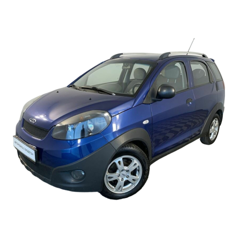
Chery A21 User manual

CHERY A21 SERVICEMANUAL MECHANISMOF2.0NALCENGINE
1
MECHANISMOF2.0NAENGINE
CONTENT
CHAPTER1ENGINEPARAMETERAND SPECIALMAINTENANCETOOLS....2
SECTION 1TECHNOLOGYDATAINSTRUCTION................................................2
SECTION 2SPECIALTOOLS...................................................................................5
SECTION 3ENGINENUMBERPOSITION.............................................................6
SECTION 4COLLATING METHOD OFENGINETIMING.....................................7
CHAPTER2ENGINEBODY........................................................................................9
SECTION 1WHEELTRAIN......................................................................................9
SECTION 2CYLINDERHEAD..............................................................................14
SECTION 3SHORTENGINE..................................................................................26
PDFcreated withpdfFactoryProtrialversion www.pdffactory.com
pouyapadid.com
09120539254

CHERY A21 SERVICEMANUAL MECHANISMOF2.0NALCENGINE
2
CHAPTER1ENGINEPARAMETERAND SPECIALMAINTENANCETOOLS
SECTION1TECHNOLOGYDATAINSTRUCTION
ENGINECHARACTER
EngineModel SQR481H
EngineType
4-Cylinder,WaterCooled, In-lineDouble
OverheadCamshaft, 16 Valve,
ControllableBurning Rate,VariableValve
Timing
CylinderDiameter mm)83.5
PistonStroke(mm) 90
Displacement(L) 1.971
CompressionRatio 10
RatedPower Kw)95
RevatRatedPower r/min)5500
Max.Torque NM)180
RevatMax.Torque r/mim)4000
MinimumFuelConsumptionRate g/Kw.h)
301
CylinderPressure Bar)10±0.2
FuelPressure Bar)4
LowIdleSpeed
800±50r/min)
HighIdleSpeed
2000r/min)
EngineOil
Pressure Bar)
HighSpeed
4000r/min)
HighPressureCircuit 2--3
A/CCircuit
Pressure Bar)
LowPressureCircuit 12---16
PressureReliefValve
ReleasePressureto
Outside)88±14.5
ExpansionTank
Cap kpa)VacuumValve LeadAir
intoTank)-10~~~~-2
StartWorking
Temperature 87Thermostat
Working
Temperature )
FullWorking
Temperature 104
PDFcreated withpdfFactoryProtrialversion www.pdffactory.com
pouyapadid.com
09120539254

CHERY A21 SERVICEMANUAL MECHANISMOF2.0NALCENGINE
3
TECHNOLOGYDATAINSTRUCTION
Item StandardValue
Intakecam 37.15
CamHeight Exhaustcam 37.05
Intakecam
CamshaftDiameter Exhaustcam
Intakecam 0.15--0.20
Camshaft
Axialclearance ofCamshaft Exhaustcam 0.15--0.20
PlaneDegree ofLowerSurface 0.04
WholeHeight 140±0.41
Cylinder
Head SurfaceGrindLimit*TotalGrinding Quantityof
CylinderBlockandHead
IntakeValve 0.3±0.15
FringeThicknessonTopofValve
ExhaustValve 0.3±0.15
IntakeValve 5.98±0.008
ValveStemDiameter ExhaustValve 5.96±0.008
IntakeValve
SealBandwidth ExhaustValve
IntakeValve 0.02
GapBetweenValveStemAndGuide
ExhaustValve 0.04
IntakeValve 65°
TiltAngle ExhaustValve 68°
IntakeValve 107.998
Valve
Height ExhaustValve 106.318
Free Height 47.7
WorkingTensioninAdvance/WorkingHeightKg/mm
620N/32mm
Valve
Spring
VerticalDegree
ValveGuideLength 38±0.25
Valve
Guide InsideDiameter 5.4±0.1
24
040.0
053.0
−
−
24
040.0
053.0
−
−
PDFcreated withpdfFactoryProtrialversion www.pdffactory.com
pouyapadid.com
09120539254

CHERY A21 SERVICEMANUAL MECHANISMOF2.0NALCENGINE
4
OuterDiameter
PressureHeight 16±0.3
ProtrudingPartofValveStem 47.5
Piston PistonSkirtDiameter 83.46±0.009
1st Ring 0.04--0.08
SideClearance
2
n
d
Ring
0.01
--
0.025
1
st
Ring
0.2--0.4
EndPlay
2
nd
Ring
0.4
--
0.6
1st Ring
2nd Ring
Piston
Ring
Height
OilRing
1st Ring
2nd Ring
Ring
Groove Height/Depth
OilRing
2.5
Diameter
Length 60
PistonPin
DiameterofPistonPinHole
AxialClearance 0.076--0.265
RadicalClearance -0.0375
CoaxialDegree 0.05
Cylindricity 0.008
CrankshaftMainshaftDiameter
Roundness
0.005
Cylindricity
Crankshaft
ConnectingRodJournalDiameter
Roundness
WholeHeight 218±0.05
CylinderHoleRoundness/StraightnessAccuracy 0.008 /0.01
Cylinder
UpperSurface Planeness 0.04
RadialClearance ofConnectingRodBearing 0.016--0.051
Connectin
gRod AxialClearance ofBigEnd 0.15--0.4
11
051.0
040.0
+
+
2
.
1
05.0
03.0
+
+
5
.
1
04.0
02.0
+
+
5
.
2
03.0
01.0
+
+
21
0
005.0−
21
008.0
002.0
2
.
1
01.0
03.0
−
−
5
.
1
005.0
030.0
−
−
PDFcreated withpdfFactoryProtrialversion www.pdffactory.com
pouyapadid.com
09120539254

CHERY A21 SERVICEMANUAL MECHANISMOF2.0NALCENGINE
5
SECTION2SPECIALTOOLS
Camshaft TimingTool
CrankshaftTimingTool
FlywheelTool
GuideSleeveofCrankshaftOil
Seal
GuideSleeveofCamshaft Oil
Seal
HydraulicHoist
PDFcreated withpdfFactoryProtrialversion www.pdffactory.com
pouyapadid.com
09120539254

CHERY A21 SERVICEMANUAL MECHANISMOF2.0NALCENGINE
6
FuelPressureGauge
CylinderPressureGauge:whenmeasurethecylinder
pressure,firstlyremovethesparkplug,screwthepipe
endofinstrumentinsteadofit,andoperatetheengineby
starter, thentakethemaximumvalueincylinderpressure
gaugeascylinderpressure.
SECTION3ENGINENUMBERPOSITION
Position ofEngineCylinderBlockNumber
EngineOil Dipstick
PDFcreated withpdfFactoryProtrialversion www.pdffactory.com
pouyapadid.com
09120539254

CHERY A21 SERVICEMANUAL MECHANISMOF2.0NALCENGINE
7
SECTION4COLLATINGMETHODOFENGINETIMING
1.Removetheuppercoverofenginetiming
belt.
2. Removethelowercoverofenginetiming
belt.
3. Loosenthecentralboltoftiming belt
tensionpulleyandremovethetiming
belt.
4. Drawoutthehighvoltageignitioncable.
PDFcreated withpdfFactoryProtrialversion www.pdffactory.com
pouyapadid.com
09120539254

CHERY A21 SERVICEMANUAL MECHANISMOF2.0NALCENGINE
8
5. Loosentheboltofvalvecoverand
removethevalvecover.
6. Rotatethecamshaftinordertoclipthe
camshafttool intotheslotattheendof
camshaft.
7. Loosentheboltsofairintakeandexhaust
camshafttensionpulleyswithtorque
wrench.
Note:Itisnottoremovebutloosen.
8. Revolving thecrankshaft,youmayrotate
inthe crankshafttool soastoitcannot
moveinbothdirection.
Note:Doitwithpatience andcarefulness lest
thecrankshaftshouldbebroken.
CamshaftTool
CrankshaftTool
PDFcreated withpdfFactoryProtrialversion www.pdffactory.com
pouyapadid.com
09120539254

CHERY A21 SERVICEMANUAL MECHANISMOF2.0NALCENGINE
9
9. Mountthetiming beltandrotatetension
pulleywithAllenwrenchinorderto
tensionthebeltandmakethefingerof
tensionerpointtothemiddleofUslot
opening.Fastentheboltoftensionpulley,
thefastening boltsofairintakeand
exhaustcamshafttensionpulleysand
camshaft.
Torque:120±5Nm.
10. Removethespecialtiming tool,and
mountthevalvecover,thehighvoltage
ignitioncableandthetiming beltcover.
CHAPTER2ENGINEBODY
SECTION1WHEELTRAIN
I. STRUCTURALDIAGRAM
PartName Torque valueNm Re-screwangle
1 Bolt–LowerPartOfTiming
FrontCover 8+3
2 Bolt–UpperPartOfTiming Front
Cover 8+3
3 Bolt–UpperPartOfTiming Front
Cover 8+3
4 LowerPartOfTiming Front
Cover
5 UpperPartOfTiming Front
Cover
6 Washer- LowerPartOfTiming
FrontCover
7 Bolt-CrankshaftTimingGear 130+10 65+5
8 Washer- CrankshaftTimingGear
9 CrankshaftTimingGear
10 TimingBelt
11 WaterPump
12 Bolt-Timing GearRearCover 5+1.5
13 TimingGearRearCover
14 CamshaftTiming Gear
15 Bolt-CamshaftTiming Gear 120+5
16 Bolt-Timing Tensioner 27+2.7
17 TimingTensioner
18 Bolt-Timing Idlerwheel 40+5
19 TimingIdlerwheel
20 ContactIdlerwheel
21 Bolt-ContactIdlerwheel 40+5
PDFcreated withpdfFactoryProtrialversion www.pdffactory.com
pouyapadid.com
09120539254

CHERY A21 SERVICEMANUAL MECHANISMOF2.0NALCENGINE
10
II. MAINTENANCE
1. Replace upperandlowercoversoftiming
belt
1.1 Neededtoolsandauxiliarymaterials
Allenwrench,10#,13#sleeve,ratchetwheel
andratchetrod.
1.2 Removal
1) Loosenthefiveboltsontheuppercover
withAllenwrench.
2) Removetheuppercoveroftiming belt.
3) Cliptheflywheelwithflywheeltool.
4) Removethecrankshaftpulleywith13#
sleeve.
FlywheelTool
PDFcreated withpdfFactoryProtrialversion www.pdffactory.com
pouyapadid.com
09120539254

CHERY A21 SERVICEMANUAL MECHANISMOF2.0NALCENGINE
11
5) Removethe5boltsonthelowercover
oftiming beltwith10# sleeve,ratchet
wheelandratchetrod.
6) Removethelowercover.
1.3 Inspection
Observethetiming coverandthetiming belt.
Replace thetiming beltcoveroradjustthe
positionoftiming beltifanytrailfromcrack
orfrictionisfound.
1.4 Installation
Theinstalling stepsarereversetothosefor
removal.
Note:Installthelowercoverfirstandthen
install theupperone.
2.Replace timing belt
2.1Neededtoolsandauxiliarymaterials
Allenwrench,10#,13#sleeve,ratchetwheel
andratchetrod.
2.2Removal
1) Removetheupperandlowercoversof
timing belt(see “replace coversof
PDFcreated withpdfFactoryProtrialversion www.pdffactory.com
pouyapadid.com
09120539254

CHERY A21 SERVICEMANUAL MECHANISMOF2.0NALCENGINE
12
timing belt”fordetails).
2) Loosenthecentralboltoftensionpulley
andremovethetiming belt.
2.3Inspection
Checkthetiming beltcarefully;replace the
partsifanyfollowing situationoccurs.
(1)Chapofback-siderubber
(2)Chapofdedendum,chapofseparated
cordfabric.
(3)Wearing,gearmissing andincomplete
gearofcordfabric.
(4)Abnormalwearingofbeltflank.
Replace thebeltasanyfollowing situationoccurs,eventhoughabrasioncannotbefound
directly.
1)Thewaterpumpleakswaterout, andrequirescontinuing infusion.
2)Ifthebeltisspottedwithmuchoil stains,andtherubbermaybedamageddueto
expansion,youshouldreplace thebelt.
Chap
Chap
Wearing
AbnormalWearing
GearMissing
Belt CoreDesquamation
PDFcreated withpdfFactoryProtrialversion www.pdffactory.com
pouyapadid.com
09120539254

CHERY A21 SERVICEMANUAL MECHANISMOF2.0NALCENGINE
13
2.4 Installation
Theinstalling stepsarereversetothosefor
removal.
Note:Doenginetiming.
3. Replace idlerwheel,tensionerand
contactbeltpulley
3.1 Neededtoolsandauxiliarymaterials
Allenwrench,10#,13#and15# sleeve,
ratchetwheelandratchetrod.
3.2 Removal
1) Removethetiming belt(see “replace
timing belt”fordetails).
2) Removeidlerwheel,tensionpulleyand
contactbeltpulley.
3.3 Inspection
1) Checkfromappearance
Checkidlerwheel,tensionpulleyandcontact
beltpulleycarefullyforanydamages, suchas
sunkentrace andsliding damageetc.
2) Checkperformance
Revolvetensionpulley,idlerwheeland
contactbeltpulleyrespectivelytoinsurethat
theycanrunfreelywithoutstagnancy.
Replace itwiththesparepartifanyabove
problemisfound.
3.4 Installation
1) Theinstalling stepsoftensionpulley,
idlerwheelandcontactbeltpulleyare
reversetothoseforremoval.
2) Mountthetiming beltandcollateengine
timing.
3) Mountotherparts.
PDFcreated withpdfFactoryProtrialversion www.pdffactory.com
pouyapadid.com
09120539254

CHERY A21 SERVICEMANUAL MECHANISMOF2.0NALCENGINE
14
SECTION2CYLINDERHEAD
I. STRUCTURALDIAGRAM
1. Gasket—IntakeManifold
2. IntakeManifoldAssembly
3. HexagonalFlangeBolt
4.ThrottleValveBodyAssembly
5. Gasket—ThrottleValveBodyAssembly
6. OilinjectorAssembly
7. FuelDistributionPipeAssembly
8. Bracket
4
7
6
2 1
3
5
8
PDFcreated withpdfFactoryProtrialversion www.pdffactory.com
pouyapadid.com
09120539254

CHERY A21 SERVICEMANUAL MECHANISMOF2.0NALCENGINE
15
1. IntakeValve
2.ValveOil Seal
3.ValveSpringSeat
4.ValveSpring
5.ValveSpringRetainer
6. Keeper
7. ExhaustValve
8. IntakeCamshaftAssembly
9. BearingCapAssembly
10. ControlValve-CamshaftPhaserAssembly
11. FirstBearingCapAssembly
12. FrontCamshaftOilSeal
13. ExhaustCamshaftAssembly
14. RockerArmAssembly
15. HydraulicTappetAssembly
16. StudBolt(9Bars)
17. CylinderHeadGasket
18.TemperatureSensor
19. EngineHanger
20. CylinderHeadBolt
21. CylinderHeadAssembly
11
15
14
13
8910
17 7
18
1
5
4
3
2
6
12
16
19
20
21
PDFcreated withpdfFactoryProtrialversion www.pdffactory.com
pouyapadid.com
09120539254

CHERY A21 SERVICEMANUAL MECHANISMOF2.0NALCENGINE
16
II. MAINTENANCE
2.1 Replace intakemanifold,deliverypipe
andoilinjector
2.1.1 Neededtoolsandauxiliarymaterials
Ratchetwheel,ratchetrod,10#sleeveand
crossheadscrewdriver
2.1.2 Process ofremoval
1) PuttheignitionkeyattheOFF position.
2) Loosentheplug ofoilinjector.
3) Removetheconnectingboltbetween
engineoildipstickandintakemanifold.
4) Removetheclampbetweenintakehose
andthrottlevalvebody.
5) Removetheconnectingboltofthrottle
valvebody,andtakeoutthrottlevalve
body.
Note:Becausethisthrottlevalvebodyis
electronic,donotforce themiddlevanes
turningmanuallyorwithotherobjects.
6) Loosenthejointofoil intakepipe.
7) Removethefastening nutofintake
manifoldandtakeouttheintake
manifold.
PDFcreated withpdfFactoryProtrialversion www.pdffactory.com
pouyapadid.com
09120539254

CHERY A21 SERVICEMANUAL MECHANISMOF2.0NALCENGINE
17
2.1.3 Installationsteps
Theinstalling stepsarereversetothosefor
removal.
2.2 Replace camshaft,bearingbushings,
valveandvalveoilseal.
2.2.1 Neededtoolsandauxiliarymaterials
Specialtoolsforvalveoil seal,engine
transmissionoil,asetofsleevetools,an
adjustablespanner,specialtoolsfortiming
andasetofAllenwrenches
2.2.2 Removal
1) Removethedynamobelt(see “removal
ofdynamobelt”fordetails).
2) Removethetiming belt(see
“replacementofenginetiming beltand
timing calibration”fordetails).
3) Removethecoverofenginevalve
chamber.
4) Clampthetiming specialtoolinto
camshaftslotandfastenthebolt.
CamshaftTool
PDFcreated withpdfFactoryProtrialversion www.pdffactory.com
pouyapadid.com
09120539254

CHERY A21 SERVICEMANUAL MECHANISMOF2.0NALCENGINE
18
5) Dismantlethebeltpulleyofairintake
andexhaustcamshaftswithtorque
wrench.
6) Removethebackcoveroftiming belt.
7) Dismantlethebearingcapsofairintake
andexhaustcamshaftrespectivelyand
putthemdowninthesequence.
Note:Thesecond,third,fourthandfifth
camshaftbearingcapsaremarkedwithI1, I2,
I3,I4(E1,E2,E3,E4),whichstandsforthe
correspondingbearingcapof1,2,3,4
cylinderrespectively.(“I”referstointake
camshaft, “E”referstoexhaustcamshaft).
Torque:
PDFcreated withpdfFactoryProtrialversion www.pdffactory.com
pouyapadid.com
09120539254

CHERY A21 SERVICEMANUAL MECHANISMOF2.0NALCENGINE
19
See thefollowing pictureforremovalsequence ofintakeandexhaustcamshaft-bearing caps:
8)Takeoutthecamshaftandthehydraulictappet.
9)Removethevalvespringwithspecialtools. (Pictureisunavailable)
10)Removetheusedvalveoil sealwithspecialtools. (Pictureisunavailable)
2.2.3 Inspection
1) Checkthevalvespring.
Measurethefree length,theverticalityand
thelengthunderspecialpressurewithcaliper.
Standard
Value(mm)
Free length 47.7
Lengthof
620N 32
Replace withthenewvalvespringifthe
measuredvalueexceedsthelimitvalue.
PDFcreated withpdfFactoryProtrialversion www.pdffactory.com
pouyapadid.com
09120539254

CHERY A21 SERVICEMANUAL MECHANISMOF2.0NALCENGINE
20
2)Checkcamshaft
Measurethe camshaft diameterwith
micrometercaliper.
StandardValue
mm)LimitValue
(mm)
Diameter
¢24-0.053-0.040
Replace withthenewcamshaftifthe
measuredvalueexceedsthelimitvalue.
3)Examinecamshaft
Measurethehighofcamwithmicrometer
caliper.
StandardValue
mm)
limitvalue
mm)
Intake
Cam 37.15
Exhaust
Cam 37.05
Replace withthenewcamshaftifthe
measuredvalueexceedsthelimitvalue.
4) Examinediameterofvalvestem
a: Measurethediameterofvalvestemwith
micrometercaliper.
See thepictureformeasuringpoints:theyare
26,52,and78 mmfrommeasurepositionsto
bottomofvalve.
Valve
Guide
ExternalDiameter
OfValveStem
InternalDiameter
OfValveGuide
MeasuringPoint
PDFcreated withpdfFactoryProtrialversion www.pdffactory.com
pouyapadid.com
09120539254
Table of contents
Other Chery Automobile manuals
Chery
Chery SQR7240T User manual
Chery
Chery V5 User manual

Chery
Chery RIICH 2 series User manual
Chery
Chery A1 2009 User manual

Chery
Chery A113 User manual
Chery
Chery Automobile User manual

Chery
Chery A5 2007 Service manual

Chery
Chery Tiggo 2009 User manual

Chery
Chery M16 Arrizo 7 2014 User manual

Chery
Chery A21 2005 User manual
