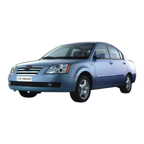
Chery A11 2003 Operating instructions

CIRCUIT
FOREWORD
New style wiring harness is designed upon chery sedan wiring harness-updating plan
approved by Chery Auto Co., LTD in July 2001. According to updated plan, concentrated control
in central electrical box is replaced with a nearby control method in design, enhancing circuit
performance, avoiding internal resistance and heat sources interference between electrical
devices and increasing the whole vehicle wiring harness reliability and endurance.
During updating, some structures and features on home and abroad famous brand name
vehicles are used for reference or equivalently taken as follows:
1. Adding whole vehicle electrical devices problem automatic safety-protect unit, which
ensure whole circuit system being cut off when sudden accident occurs to avoid possible fire
hazard or other injury from short problem.
2. Selecting a new central electrical box mainly used for whole vehicle control circuit, in
which there are 6 built-in mini relays, 24 type fuses, 3 intensive safety protect units and 58
external connecting points.
3. High current and power electrical devices are nearby controlled, such as fan and A/C
control circuit are directly completed at front compartment harness, shortening the current path.
Comparing with old wiring harness, main changes in wiring harness and electrical devices
are as follows:
Interior harness, front compartment harness, I/P (instrument panel) harness, battery positive
harness, central electrical box, two front and rear fog light switches instead of one switch on old
vehicle, and also relevant changes in ABS harness connector.
But control theory and whole vehicle harness routing mainly keep unchanged.
Only whole vehicle electrical devices theory illustrations are available in this manual and
there exists difference with actual electrical devices circuit. For convenience of compiling and
printing, some big circuits page are divided into several small pages, which will take
inconveniences when reading and therefore will require the user have a good command of
circuits on SQR710 sedan.
For compilers’ knowledge and time limits as well as rapid technology updating, some
errors and oversights are hard to avoid and kindly appreciate for users’ pointing out with the idea
of improving together. Electrical system are rapidly updated, therefore some new circuit are not
compiled on this manual on the time of publishing and will be supplemented timely.
This manual is compiled by Chang Yongjiu, Yao Shen and reference books are supplied by
product department.
Written by compilers
November 2002

CIRCUIT
TOTAL CONTENT
No.1 Central Electrical Box Fuse And Relay Position (2 Pages)
No.2 Central Electrical Box Connector Position And Function (3 Pages)
No.3 CircuitManualExplanation (2Pages)
No.4 Circuit (23Pages)
No.5 ETVehicleCircuit (25Pages)

No.1 CIRCUIT CentralElectricalBoxPosition(InCabin,UnderSteeringWheel)
A/C Clutch Sunroof Cab License Plate Lamp
Ceiling Light Luggage
Compartment Light Sound
Headlight
Switch Rear Window
Heater
Gauge Wiper A/C
Horn Fog light
Brake Light Thermo Switch Glass Lifte
r
Central Locking
Cigar Lighter Emergency
Warning Indicato
r
Gauge
Anti-Theft Unit Power Mirror Back Light
Milea
g
e Senso
r
ABS Fuse
ABS Fuse
Wiper Relay
Emergency
Warning Relay
Central Electrical Box Position
(
In Cabin
,
Under Steerin
g
Wheel
)
—1 —

CIRCUIT Relay, Fuse Layout, Central Electrical Box Fuse Position (In cabin, Under Steering Wheel)
Central Electrical Box Fuse position
(In Cabin, Under Steering Wheel)
Sunroof Cab License Plate Lamp
Back Light
Milea
g
e Senso
r
Rear Window
Heate
r
Glass Lift
Gauge
A/C
Emergency
Warnin
g
Indicato
r
Thermo Switch
Glass Lift Anti-Theft Unit
Headlight
Switch
Fog Light
Wipe
r
Ceiling lamp Luggage
Compartment Lamp Sound
Brake Light
Cigar Lighte
r
A/C Clutch
Horn
Gauge
Re
l
ay B
l
oc
k
Fuses Pos
i
t
i
on(II)At Right side of Front Compartment
Radiator Fan Control
Relay, Fuse Position (I) Beside Washing Reservoir
High Spee
d
Low Speed
Headlight
Low–High
Beam Relay
A/C Relay
N
OTE: 50A fuse is used when two fans works.
High Speed
Relay
30Right High Beam Fuse
29 Left Low Beam Fuse
28Left Position Light Fuse
27Left High Beam Fuse
32Right Low Beam Light
31Right Position Light Fuse
Low Speed
Relay
—2 —

CIRCUIT Central Electrical Box Connector Position
Central Electrical Box Connector Position
( FRONT SIDE VIEW )
( BACK SIDE VIEW )
—
1 —

CIRCUIT Central Electrical Box Connector Position
Central Electrical Box Connector, Pin and Function
Connector Connector Pin Function Circuit
No.
A
01.Sunroof, Cab Freight Calculator (+15)
02.ECUA/C Signal Input
03.——
04.Luggage Compartment Lamp, Radio, Ceiling Lamp
05.——
06.——
07.——
08.——
09.Rear Window Preheat Switch, Rear Mirror Defrost
Switch
10.——
11.Lamp Switch Illumination, ABS Diagnostic Power
(+15)
12.——
13.Combination Instrument Power Positive (+30)
14. Brake Switch
—
138
—
247
—
—
—
—
134
—
132
—
114
192
B
01.——
02.——
03.——
04.A/C Relay, Blower, Interior Circulate Solenoid
Switch
—
—
—
51
C
01.Horn Switch
02.Fog Lamp Relay (Positive)
03.Fog Lamp Switch
04.Horn Relay Signal (30)
05.Dual Pitch Horn
06.Wiper Motor (Positive)
07.Panel Indicator, Switch Illumination Light, Light Switch
Variable Resistor
08.Back Light Switch
09.——
10.——
11.——
12.Fog Lamp Relay (Positive)
13.——
14.——
15.Thermo Switch,A/C High Pressure Switch
16.Central Electrical Box Power Positive (+30)
142
219
220
140
141
154
209
83
152
—
—
215
—
—
47
6
—
2 —

CIRCUIT Central Electrical Box Connector Position
CIRCUIT__Central Electrical Box Connector, Pin and Function
Connector Connector Pin Function Circuit
No.
C
17.——
18.Wiper Intermittent Relay
19.Lincense Plate Lamp
20.Mileage Gauge Sensor
—
149
210
81
D
01.——
02.Cigar Lighter
03.Turn Light Switch, Headlight Adjustment
Switch
04.——
05.Combination Instrument Positive (+15)
06.Sunroof, Cab Freight Calculator (+30)
07.Ground
08.——
09.Rear View Mirror、Lifter Module、 Position Select
Box (+15)
10.Ignition Switch (+15)
11.Central Locking Controller, Glass Lifter Module
(+30)
12.Ignition Switch, Wiper Switch (+15)
13.Central Electrical Box Power Positive (+30)
14.——
15.——
16.——
—
129
175
—
116
—
53
—
272
14
260
8
10
—
—
248
E
01.——
02.——
03.——
04.A/C Compressor Magnetic Clutch
05.——
06.——
07.——
08.Central Electrical Power Positive (+30)
09.Ignition Switch (+15)
10.Lamp Switch
11.——
12.Horn Relay
13.——
14.——
—
—
—
137
—
—
—
5
9
207
—
139
—
—
—
3 —

No.3 CIRCUIT
CIRCUIT MANUAL EXPLANATION
—1 —

CIRCUIT
Compiling Explanation
1. Central Electrical Box Main Circuit Board Circuit No.
30:No Fuse, Positive Goes Directly From Battery
15:No Fuse, Positive Goes To Ignition----Start Switch
X:No Fuse, Positive Goes To Ignition ----Start Switch,And Being Cut Off During Starting
31:Fictitious Ground, This wire actually exists or does not actually exist.
Example: 30(E8) defines these 30 hot wires are directly from battery, and come from central
electrical box socket E pin No. 8.
30(C16)、15(D10)、X(D12)…are similar as 30 (E8)
2. Central Electrical Box Main Circuit Board Block
This block on main circuit board includes fuse, relay and connection interface.
3. Wire routes as follows:
——coming from right side on previous page
——going to left side on next page
4. Central Electrical Box Main Circuit Board Pins No.
It will be helpful for locating main circuit board circuit, such as E/8 indicates the 8th pin on central
electrical box socket E.
5. Wire colors and cross-area, square millimeter
6. Connection Symbol
This symbol is signed on component.
7. Parts or components name (illustrated on left bottom of each page).
8. symbol for wire continuing
Number in square form indicates wire number or appropriate extending wire no.
9. Internal wire
Used for locating internal wire. This wire may actually exist or does not exist.
10. Ground point
Indicated by number in circle, and the point is also indicated on circuit.
11. Circuit number
Used to locating component and interrupted wire connecting point.
12. Multi-hole connector connecting points
Socket terminal numbers are given.
—2 —

CIRCUIT
CONTENT
——Battery,Alternator, Starter Motor, Ignition Switch 01·········································································
···········································································································
·····················································································
······················································································
·········································
····················································································································································
·····················································································································
·····································································································
······································································
····························
··········································································································
·················································································
·······················································
··································································································
··································································································································
···········································································································
·························································································································
·············································································································
·····························································································································
·································································································································
···············································································································································
····································································································
································································································
——SPI EI System (MARELLI) 02
——MPI EI(Electronic Injection) (MARELLI) 02
——A/C Unit, Control Head, Cooling System 03
——A/C Switch, Interior Circulate Solenoid, High & Low Pressure Switch 04
——Oil Pressure Switch, Coolant Temperature Sensor, Manual Brake Indicator Switch, Mileage Gauge
Sensor 05
——Radio and 6 Speakers 06
——IP (Instrument Panel) and MFA 07
——Front Fog Light, Cigar Lighter, A/C Panel Indicator 08
——Rear Window Heating System, Dual Pitch Horn, Compressor Magnetic Clutch 09
——Wiper, Horn Button, Washer 10
——Headlight, Front Position Light, Light Relay 11
——Turn Light, Parking Light Switch, Emergency Warning Relay 12
——Taillight, Side Light, Brake Light 13
——Light Switch 14
——Back Light, Rear Fog Light 15
——Headlight Adjuster 16
——Front & Rear Interior Light, Luggage Compartment Illumination Light, Sun Visor Light, License
Plate Light, Door Touch Switch 17
——Central Locking 18
——Power Mirror 19
——ABS 20
——Power Glass Lifter Control Unit 21
——Power Glass Lifter Control Switch 22

CIRCUIT
Battery,Alternator, Starter Motor, Ignition Switch
○
1G round, At Ground Carrier Beside Central Electrical Box
○
2Body Ground, Near Battery
○
3Engine Ground Point, Located Beside Transmission
TQ4 2 Holes Match Connector
A Battery
B Starter Motor
C Alternator
C1 Voltage Regulator
D Ignition Switch
B=White
N=Black
R=Red
M=Brown
V=Green
A=Blue
H=Grey
Z=Purple
G=Yellow
—1 —

SPI Electronic Injection (Marelli)
B=White
N
=Black
R=Red
M=Brown
V=Green
A=Blue
H=Grey
Z=Purple
G=Yellow
J=Orange
F=Pink
J200 SPI controller unit
G42 Air Intake Temperature Sensor
G62 Water Temperature Sensor
G69 Throttle Position Sensor
G19 Air Intake Pressure Sensor
N
30 Active Carbon Canister Solenoid
G28 Crankshaft Position Sensor
G39 Oxygen Sensor
G35 System Fuse
S36 Oil Pump Fuse
A+ Battery Positive
J176 ECU Relay
J17 Power Relay
N
1 Cylinder 1—4 Ignition Coil
N
2 Cylinder 2---3 Ignition Coil
Q Spark Plug
N
80 Fuel Injecto
r
G Fluid Level Sensor
G6 Fuel Pump
TK Diagnostic Socket
(4) Ground On Engine
Ground point
-2a-

Blue yellow
red
black
-2a-

CIRCUIT
MPI Electronic Injection (Marelli)
B=White
N
=Black
R=Red
M=Brown
V=Green
A=Blue
H=Grey
Z=Purple
G=Yellow
J=Orange
F=Pink
J300 MPI Controller Unit
S81 Air Intake Pressure Sensor
G69 Air Intake Temperature Sensor
JS14 Water Temperature Sensor
S42 Knock Sensor
S12 Crankshaft Position Sensor
L99 Power Relay
FS 35 System Fuse
FS 36 ECU Power Fuse
FS 37 Oxygen Sensor Fuse
A+ Battery Positive
L01-04 Fuel Injector
L05 Ignition Coil
Q SparkPlug
S71 Oxygen Sensor
L07 Carbon Canister Solenoid
TK Diagnostic Connector
M27 Idle Step Motor
G Fuel Level Sensor
G6 FuelPump
○
4Ground on Engine
TSPI Connector
TP Connector
TD Connector
N
ote: ECU CONNECTOR 1-(1-52 PIN)
ECU CONNECTOR 2-
(
53-80 PIN)
1
-2b-

CIRCUIT
2
-2b-

CIRCUIT
A/C Unit, Control Head, Cooling System
B=White
N
=Black
R=Red
M=Brown
V=Green
A=Blue
H=Grey
Z=Purple
G=Yellow
A+ battery positive
E9 blower switch
F18 thermo switch
N
23 blower in-line speed
regulator resistance
V2 blower
V7 fan motor
J32 A/C relay
J69 Cooling fan high speed relay
J70 Coolin
g
fan low s
p
eed rela
y
J5 A/C blower relay (in electrical box)
J6 Rear Window preheat relay
○
5 ground, in wiring harness in boot I
○
6 ground, on ground carrier beside central electrical box
3

CIRCUIT
A/C UNIT SWITCH, INTERIOR CIRCULATION SOLENOID, HIGH & LOW PRESSURE
SWITCH
B=White
N
=Black
R=Red
M=Brown
V=Green
A=Blue
H=Grey
Z=Purple
G=Yellow
E35 A/Cunitswitch
E36 Interiorcirculationswitch
K84 A/C operating illumination switch ○
7○
8 Main circuit ground
N
63 Interior circulation solenoid TK 5 holes connecto
r
F38 Outside temperature switch
F23 High pressure switch
F73 Low pressure switch
4

CIRCUIT
OIL PRESSURE SWITCH, COOLANT TEMPERATURE SENSOR, MANUAL BRAKE
INDICATOR SWITCH, ODOMETER SENSOR
B=WHITE
N
=BLAC
K
R=RED
M=BROWN
V=GREEN
A=BLUE
H=GREY
Z=PURPLE
G=YELLOW
G2 Coolanttemperaturesensor ○
9 ground, on engine cylinder
F22 Oil pressure switch (low pressure) ○
10 ground connection, in headlight wiring harness
F9 Manual brake indicator switch TQ1 10 holes connector
F34 Brake fluid level warning switch TS2 10 holes match connector
G40 odometer sensor
5

CIRCUIT
RADIO AND 6 SPEAKERS
B=WHITE
N
=BLAC
K
R=RED
M=BROWN
V=GREEN
A=BLUE
H=GREY
Z=PURPLE
G=YELLO
Rradio
R2 front left speaker T8 8 holes connector
R3 front right speaker T1 single hole connector
R4 right rear speaker
R5 left rear speaker
R6 left front speaker
R7 right front speaker
R1 antenna
6

CIRCUIT
INSTRUMENT PANELAND MFA
B=WHITE
N
=BLAC
K
R=RED
M=BROWN
V=GREEN
A=BLUE
H=GREY
Z=PURPLE
G=YELLOW
F10 multi way converter K3 right turn indicator Y1 digital cloc
k
F15 voltagestabilizer K4 enginechargingindicator T1 singleholeconnector
G20fuelsensor K5 manualbrakewarninglight
G25 coolant temperature sensor K6 engine self-check indicator
G30RPMsensor K7oilpressurewarninglight
G35 preset fluid level compare meter K8 engine overheat warning light
J114 control unit K9/K10/K11/K12 instrument panel illumination light
J119 multi function display K13 low beam headlight, position warning light
K1 ABS warning indicator K14 high beam warning light
K2leftturnindicator K15fuelwarninglight
7
Table of contents
Other Chery Automobile manuals
Chery
Chery A5 2007 Service manual

Chery
Chery Tiggo 2009 User manual
Chery
Chery T21 2014 User manual

Chery
Chery Tiggo 5 T21 User manual
Chery
Chery S18D User manual

Chery
Chery V5 User manual

Chery
Chery TIGGO User manual
Chery
Chery QQ3 User manual
Chery
Chery RIICH 2 series User manual

Chery
Chery M16 Arrizo 7 2014 User manual

