CHESTER Super Lux Mill User manual


2
Warning: Failure to follow these rules may result in serious personal injury!
As with all machine there are certain hazards involved with the operation and use of the
machine. Using the machine with respect and caution will considerably lessen the
possibility of personal injury, if normal safety procedures are overlooked or ignored, the
operator could be injured or the machine may be damaged.
This machine was designed for certain applications only. We strongly recommend that
this machine is not modified and/or used for any other operation other than for which it was
designed.
Safety Rules
1. For your own safety, read this instruction manual carefully before operating the
machine, learn the machine application and limitations as well as the specific hazards
particular to this type of machine.
2. Keep guards in place and in working order.
3. Make sure that the machine is correctly grounded. If the machine is with a three
pronged plug, it should be plugged into a three prong socket. If an adaptor is used to
accommodate a two-prong socket, the adaptor lug must be attached to a known ground.
Never remove the third prong.
4. Remove any adjusting keys and wrenches, form a habit of checking to see that keys
and adjusting wrenches are removed from the machine before turning it on.
5. Keep the work area clean. Cluttered areas and benches invite accidents.
6. Do not use this machine in dangerous environments, do not used this machine in damp
or wet locations or expose it to rain. Keep the work area well lit.
7. Children and visitors should be kept away from the machine and a safe distance from
the work area.
8. Make the workshop “childproof” with padlocks, master switches or by removing starter
switches.
9. Do not force a tool or an attachment to perform a task for which it was not designed.
10. Wear proper safety apparel, loose clothing, gloves, neckties, rings, bracelets and other
jewellery to ensure that they do not get caught in moving parts. Non-slip footwear is
recommended as is protective hair coverings to contain long hair.
11. Always wear eye protection such as goggles or glasses. Always use a face mask if
machining materials that create dust.
12. Make sure that the workpiece is securely clamped, use a vice or suitable clamps.
Never use hands to hold a workpiece.
13. Don’t overreach, keep a proper footing and balance at all times.
14. Keep tools in top condition, keep tools sharp and clean for the best and safest
performance and follow instructions for lubricating and changing accessories.
15. Disconnect the power before carrying out any maintenance or changing accessories
such as blades, bits and cutters etc.
16. Only use recommended accessories, the use of improper accessories may cause

3
injuries to the operator or damage to the machine.
17. Make sure the power switch is in the off position before plugging in the power supply.
18. Never stand on the machine, the machine could tip over or injuries can be caused if the
cutting tool is contacted.
19. Check for any damaged parts before using the machine, check the guards and other
parts to see that they are functioning correctly. Check the alignment of moving parts
and any mounted parts and any other condition that may affect the machines operation.
Any damaged components should be removed and either repaired or replaced before
starting the machine.
20. Only feed the workpiece into a blade or cutter against the direction of rotation of the
blade or cutter.
21. Never leave the tool running unattended, make sure that the machine has come to a
complete stop and the power has been turned off before leaving the machine.
22. Do not operate this machine whilst under the influence of alcohol, drug or medication.
23. Make sure that the power supply is disconnected while the motor is being mounted,
connected or reconnected.
Additional Safety Rules for Mills
1. Be sure that the drill bit or cutting tool is securely locked in the chuck.
2. Be sure that the chuck key is removed from the chuck before turning on the power.
3. Adjust the table or depth stop to avoid drilling into the table.
4. Shut off the power, remove the cutting tool and clean the table before leaving the
machine.
5. Use clamps or a vice to secure the workpiece, do not use your hands as the workpiece
can rotate with the drill bit or cutting tool.
6. Do not use gloves when operating a mill to prevent being caught in the rotating parts.

4
Specification
Max. drilling capacity
32mm
Max. face milling capacity
80mm
Max. end milling capacity
32mm
Table size
240 x 800mm
Cross travel
190mm
Longitudinal travel
560mm
Spindle taper
R8
Spindle stroke
120mm
T-slot size
14mm
Spindle speeds
96-1600rpm
Headstock tilt
±90º
Motor
1kW (1.5hp)
Net weight
300kg
Dimensions (LxWxH)
880 x 780 x 1150mm
5
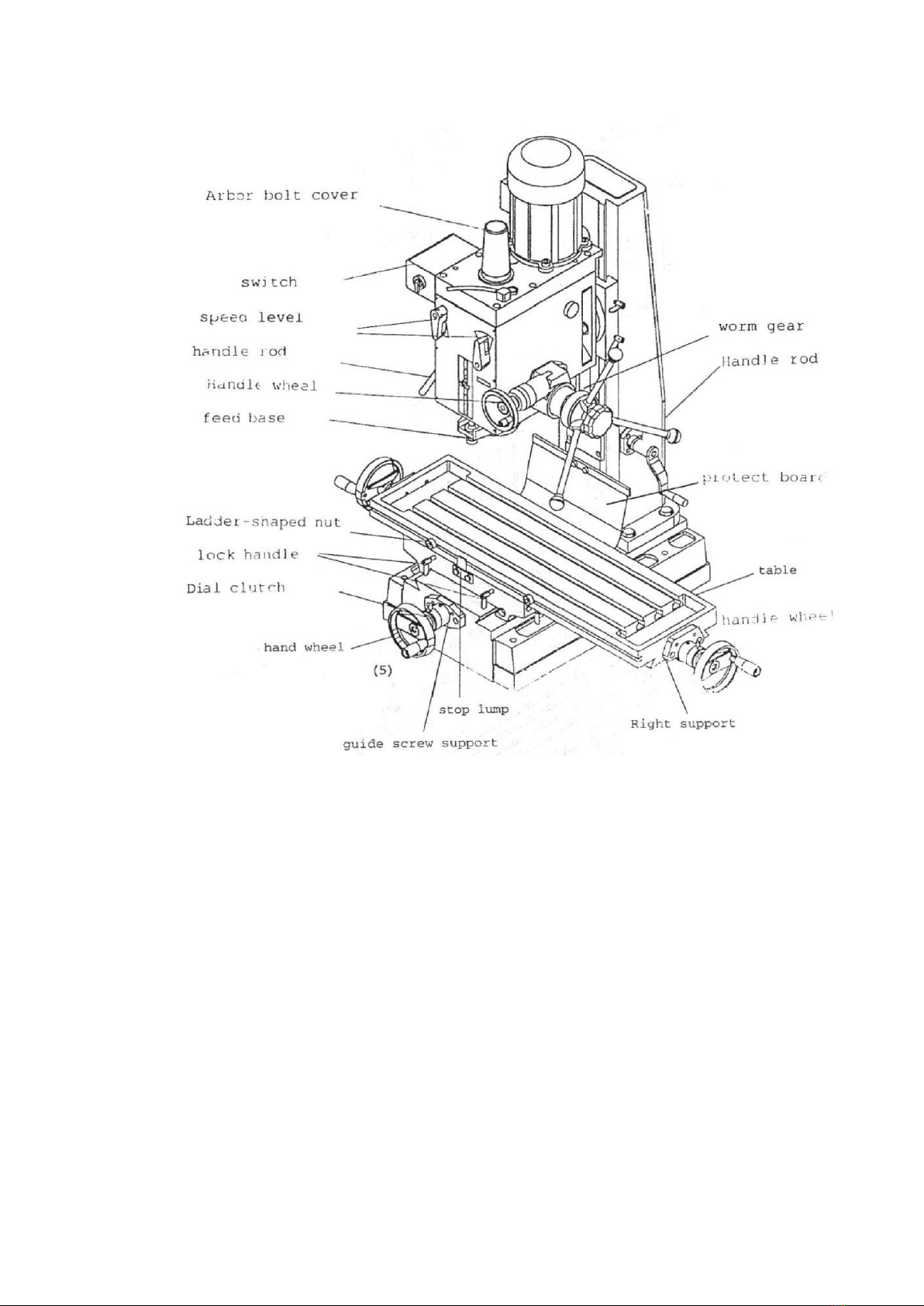
Fig.1
Speed change
The main driving route of the machine is as follows: Motor – three groups of gears – splined
sleeve – spindle, when using a motor with 1400rpm as power, six spindle speeds from
120rpm to 1970rpm can be achieved by shifting the position of the sliding gears. Make
sure that the spindle has come to a complete stop before changing the spindle speeds, turn
off the power and turn the speed change handle to the required position.
There are two forms of spindle feed available on this machine, one is the direct feed form:
the spindle feed is performed by the drilling handle on the gear shaft directly. Under this
condition, the spindle feeds 88mm as the gear shaft turns once. The other form is the
micro feed, when the hand feed wheel drives the worm gear through the cone clutch to
drive the gear shaft to feed the spindle. The spindle will feed 2.5mm when the micro feed
handwheel is turned once.

6
Cleaning
1. This machine has been coated with a heavy grease to protect it when it is delivered, this
coating should be completely removed before operating the machine. Commercial
degreaser, kerosene or similar solvent may be used to remove the grease from the
machine but avoid getting solvent on belts or other rubber parts.
2. After cleaning, coat all bright work with a light lubrication, lubricate all points with a
medium consistency machine oil.
Lubrication
All ball bearings in your mill/drill are sealed for life, requiring no lubrication. Points requiring
lubrication are:
1. Internal spline drives assembly. Keep this area well lubricated with good grade
non-hardening grease. Insert grease in the hole at the top of spindle pulley spline driver.
Lube twice yearly.
2. A light film of oil applied to the quill and column will reduce wear, prevent rust, and
assure ease of operation.
3. Quill return spring should receive oil (SAE 20) once yearly. Remove cover plate and
apply oil with squirt can or small brush.
4. IMPORTANT: The gear box should be oiled with a lubricant such as SAE 68 oil in level.
CHANGE OIL EVERY ONE YEAR.
Change the gear oil:
Tilt the head stock over as shown in Fig 2. Open the oil drain plug to allow the oil to drain
from the opening completely. Then lock the oil drain plug and turn the head to be upright
position. Remove the oil filler plug fill the oil to the gear box until the oil lever reach the
middle of oil fluid lever indicator. Then lock the plug.
5. Apply Lubricant to quill pinion every 90 days.
6.
Note: use extreme care when performing this operation and keep hands clear of pinch
points. When using paraffin bar, do this only by turning the sheaves by hand. Do not apply
with motor running.

7
Precaution for operation
Check all parts for proper condition before operation; if normal safety precautions are
noticed carefully, this machine can provide you with standing of accurate service.
1.Before operation
a) Fill the lubricant.
b) In order to keep the accurate precision, the table must be free from dust and oil
deposits.
c) Check to see that the tools are correctly set and the work-piece is set firmly.
d) Be sure the speed is not set too fast.
e) Be sure everything is ready before use.
2. After operation
a) Turn off the electric switch.
b) Turn down the tools.
c) Clean the machine and coat it with lubricant.
d) Cover the machine with cloth to keep out the dust.
3. Adjustment of head
a) Head may be rotated 360°by loosening the two heavy duty head lock nuts. Adjust the
head to the desired angle, and then fix the heavy duty head lock nuts. It is tighten the
same time to fix the head if drilling too much.
b) Unscrew nuts while the work-piece needs to be bevel drilling turn to the degrees you
wish on the scale, and then screw the nuts.
Fig.2
4.Preparing for drilling (see Fig.3).
Turn off the knob make loose the taper body of worm gear and spring base. Then we
decide spindle stroke setting the positive depth stop gauge for drilling blind hole or Free
State for pass hole.
5. Preparing for milling (see FIG.3)
a) Adjust the positive depth stop gauge to highest point position.
B) Turn tight of the knob is use to taper friction force coupling the worm gear and
spring base. Then turning the handle wheel by micro set the spindle of work piece
machining height.

8
C) Lock the rack sleeve at the desired height with fixed bolt.
Fig.3
Quill returns spring adjustment
Spring tension for return of spindle, after hole drilling, has been pre-set at the factory. No
further adjustment should be attempted unless absolutely necessary. Adjustment will
probably be required if a multiple spindle drilling or tapping head is used. If adjustment is
necessary, loosen lock screw while holding quill spring housing. Do not allow the housing
to turn in your hand, or spring will unwind. Turn entire housing assembly clockwise the
number of turns necessary to cause the quill to return to its up position. (Note: The flat of
the spring housing pilot is lined up with the spring loading hole on the body of the spring
housing.)
Reset lock screw make sure point of screw mates to flat on the housing journal.
Adjusting table slack and compensate for wear (see fig.4)
1. Your machine is equipped with jib strip adjustment to compensate for wear and excess
slack on cross and longitudinal travel.
2. Clockwise rotation the job strip bolt with a big screw for excess slack otherwise a little
counter clockwise if too tight.
3. Adjust the jib strip bolt until feel a slight drag when shifting the table.
Clamping, table base, and machine base (see fig.4)
1. When milling longitudinal feed, it is advisable to lock the cross feed table travel to insure
the accuracy of your work. To do this, tighten the small leaf screw on the right side of the
table base.
2. To tighten the longitudinal feed travel of the table for cross feed milling, tighten the two
small leaf screw on the front of the table base.
3. Adjustable travel stops are provided on the front of the table for control of cross travel
and the desired milling length.

9
Fig.4
To change tool
1. Removing face mill or drill chuck arbor.
Loosen the arbor bolt at the top of the spindle shaft approximately 2 turns with a wrench.
Rap the top of the arbor bolt with a mallet.
After taper has been broken loose, holding chuck arbor on hand and turn detach the
arbor bolt with the other hand.
2. To install face mill or cutter arbor.
Insert cutter and cutter arbor into the taper of spindle. Tighten arbor bolt detach securely,
but do not over-tighten.
3. Removing taper drills.
a) Turn down the arbor bolt insert the taper drill into the spindle shaft.
b) Turn the rapid down handle rod down until the oblong hole in the rack sleeve
appears. Line up this hole with the hole in the spindle. Insert key punch key through
holes and strike lightly with a mallet. This will force the taper drill out.

10
Electric system

11
Trouble Shooting
Problem
Cause
Solution
Excessive vibration
•Motor out-of-balance
•Bad Motor
•Balance or replace problem motor
•Replace motor
Motor stalls
•Over feeding
•Dull drill
•Motor not building up or
running to speed
•Bad motor
•Reduce feed rate
•Sharpen drill
•Replace or repair motor. Check
fuses in all three legs on three
phase motors if necessary
•Replace motor
Noisy operation
•Excessive vibration
•Improper quill adjustment
•Noisy spline
•Noisy motor
•Check remedy under excessive
vibration
•Adjust quill
•Lubricate spine
•Check motor bearings or for loose
motor fan
Drill or tool heats up or
burns work
•Excessive speed
•Chips not clearing
•Dull tool
•Feed rotate too slow
•Incorrect rotation of drill
•Failure to use cutting oil or
coolant (on steel)
•Reduce speed
•Use pecking operation to clear
chips
•Sharpen tool or replace
•Increase feed to clear chips
•Reverse motor rotation
•Use cutting oil or coolant on steel
Drill leads off
•No drill spot
•Cutting lips on drill off center
•Quill loose in head
•Bearing play
•Center punch or center drill work
piece
•Regrind drill
•Tighten quill
•Check bearings and repeat or
replace if necessary
Excessive drill runout or
wobble
•Bent drill
•Bearing play
•Drill not seated properly in
chucks
•Replace drill .do not attempt to
straighten
•Replace or reseat bearings
•Loose, reseat and tighten chuck
Work or fixture
comes loose or spins
•Failure to clamp work-piece or
work holding device to table
•Clamp work-piece or work holding
device to table surface

12

13
Head Body
1 lock nut 41 separating ring 81 arbor bolt cover base
2 lock washer 42 worm shaft 82 arbor bolt cover
3 ball bearing 43 worm cover 83 cap
3(1) washer 44 screw 84 retaining ring
4 sleeve 45 screw 85 ball bearing
5 fixed bolt 46 graduation plate 86 gear
6 scale-board 47 handle wheel 87 key
7 screw 47(1) screw 88 steel ball
8 pin 48 screw 89 spring
9 graduated rod 49 worm gear 90 key
10 feed base 50 spring 91 shaft III
11 nut 51 handle rod 92 gear
12 washer 52 handle ball 93 gear
13 screw 53 handle body 94 gear
14 nut 54 big ripple handle 95 retaining ring
15 support 55 fixed tight collar 96 gear
16 pin 56 oil cover 97 key
17 knob 57 oil pointer 98 key
18 ball bearing 58 head body 99 shaft II
19 bearing cup 59 fixed nut 100 gear
20 spindle 60 fixed tight collar 101 retaining ring
21 electric box 61 handle rod 102 separating ring
22 screw 62 nut 103 motor
23 speed lever 63 screw 104 key
24 name plate 64 pin 105 gear
25 oil seal 65 spring base 106 motor
26 retaining ring 66 washer 107 screw
27 lever shaft (left) 67 spring plate 108 key
28 lever (left) 68 spring cap 109 oil seal
29 screw 69 washer 110 head body cover
30 nut 70 washer 111 pin
31 pin 71 small ripple handle 112 screw
32 lever bracket 72 airtight ring 113 pipe radiator
33 lever shaft(right) 73 airtight base 114 oil seal
34 lever(right) 74 washer 115 retaining ring
35 pin 75 screw 116 retaining ring
36 screw 76 oil seal 117 oil cap
37 pinion shaft 77 gear 118 degree-meter
38 key 78 key 119 screw
39 feed cover 79 gear 120 screw
40 ball bearing 80 ball bearing

14
BASE PARTS

15
Base Parts
NO.
NAME
NO.
NAME
1
Base
18
Lock handle
2
Screw
19
Screw
3
Guide screw nut
20
Stop lump
4
Protect board
21
Gib screw nut
5
Ball bearing
22
Bolt
6
Guide screw support
23
Gib strip
7
Oil cup
24
Screw
8
Pin
25
Right support
9
Screw
26
Guide screw nut
10
Graduation plate
27
Guide screw
11
Screw
28
Table
12
Pin
29
Ladder-shaped nut
13
Dial clutch
30
Stop lump
14
Hand wheel
31
Screw
15
Screw
32
Oil cup
16
Slip saddle
33
Gib strip screw
17
Steel ball

16
Column and support

17
Column and support parts
NO.
NAME
NO.
NAME
1
Protect board slice
19
Gear
2
Bolt
20
Ball bearing
3
Protect board
21
Retainer ring
4
Bolt
22
Key
5
Protect board fixed
23
Guide screw
6
Column
24
Column nut
7
Gear shaft
25
Antirust plate
8
Ball bearing
26
Screw
9
Head raise bracket
27
Nut
10
Oil cup
28
Washer
11
Screw
29
Bit
12
Washer
30
Toruise and lower
13
Bolt
31
Screw
14
Round nut
32
Lock handle
15
Tab washer for round nut
33
Steel ball
16
Head raise bracket
34
Column nut
17
Screw
35
Gib strip
18
Ball bearing
Table of contents
Other CHESTER Power Tools manuals


