CHESTER 830VS User manual


Warning: Failure to follow these rules may result in serious injury.
1. For your own safety, carefully read this instruction manual before operating the
machine, learn the machines application and limitations as well as the specific
hazards associated with this type of machine.
2. Always keep the guards in place and in working order.
3. Always wear eye protection, normal glasses only have impact resistant lenses and
are not suitable as safety glasses, also use a face or dust mask if the cutting
operation is dusty.
4. Remove any adjusting keys and wrenches before operating the machine.
5. Keep the work area clean and clear of any obstacles.
6. Do not use the machine in a dangerous environment, do not expose the machine
to rain or use the machine in damp or wet conditions. Keep the work area well
lighted.
7. Keep children and other visitors away from the machine and the work area.
8. Make the workshop childproof by using padlocks, master switches or by removing
any starter keys.
9. Do not force a machine to do a job for which it was not designed and only use the
machine at a rate for which it was designed.
10.Only use an extension cord that is in good condition and that is suitable for the
current that this machine will draw. An undersized cord will cause a drop in the
line voltage which will result in a loss of power and overheating. If in doubt, use a
larger than necessary cable for this machine.
11.Wear the appropriate safety clothing and do not wear loose clothing, gloves,
neckties, rings, bracelets or other jewellery that can get caught in the moving parts
of the machine. The use of non-slip footwear is recommended as is wearing a
protective hat or a hairnet to contain long hair.
12.Make sure that the workpiece is secured in a vice or with the appropriate clamps,
do not attempt to hold the workpiece by hand.
13.Do not overreach, maintain a proper footing at all times.
14.Keep the tooling sharp and clean for the best and safest performance, follow the
instructions for lubricating and changing accessories.
15.When performing any maintenance or changing accessories such as cutting tools
etc. make sure that the machine has been turned off.
16.Make sure that the switches are in the off position before starting the machine to
reduce the risk of accidents due to unintentional starting.
17.Only ever use the recommended accessories, the use of improper accessories
may cause injury or damage the machine.
18.Never stand on the machine, it could tip or the cutting tool could be unintentionally
caught causing injury to the user.
19.Before starting the machine, check for any damaged parts such as guards or
covers and that they can be safely operated and that they will perform their
intended function. Check the alignment of the moving parts, for any binding of the
moving parts, any broken parts and the mounting of any parts that may affect the
machines operation. A guard or other part that is damaged should be repaired
correctly or replaced.
20.Only feed work into the cutting tool against the direction of rotation of the spindle.
21.Never leave a machine running unattended, make sure that the machine is
disconnected from the power supply and has come to a complete stop before
leaving it.
22.Make sure that the machine is disconnected fromthe power supply while the motor
is mounted, connected or disconnected.
Grounding Instructions
In the event of a malfunction or a breakdown, grounding provides a path of least
resistance for the electrical current to reduce the risk of electric shock. This machine
has been equipped with an electric cable with an equipment-grounding conductor and
a grounding plug.
The plug must be plugged into a matching outlet that has been correctly installed and
grounded in accordance with the local laws and regulations.
Do not modify the plug provided, if it will not fit the outlet, have the correct outlet
installed by a qualified electrician.
Improper connection of the grounding conductor can result in a risk of electric shock.
The conductor has been insulated with a green and yellow stripe jacket, if repair or
replacement of the cable is required, do not connect the earthing cable to a live
terminal.
Only ever use 3 core cables and three prong grounding plugs when using this machine
and repair or replace the plug or cable if they are damaged immediately.
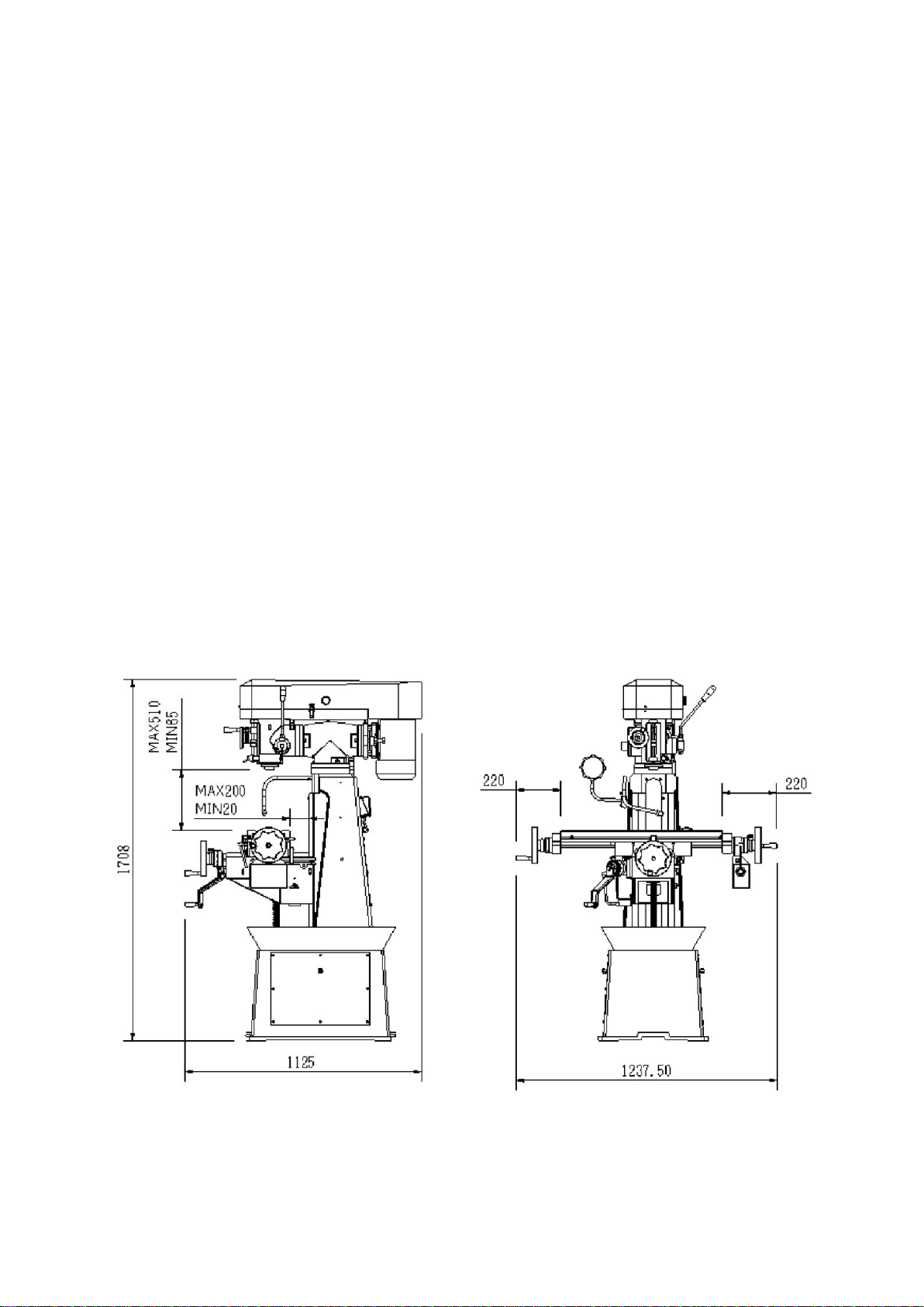
Machine Dimensions

Specifications
Spindle Taper
R8
Spindle Travel
88.9mm
Spindle Speed
200-2250rpm
Distance Spindle to Table Surface
57-510mm
Size of Worktable
205x760mm
Size of T-Slots
14mm
Number of T-Slots
3
Maximum Longitudinal Travel of Table
470mm
Maximum Cross Travel of Table
200mm
Vertical Travel of Table
455mm
Leadscrew for Drill Chuck
3mm Pitch
Vertical Head Tilt Angle
±90°
Head Swivelling Angle
360°
Motor
1.13kW (1.5Hp)
Net Weight
450Kg
Size
1100x1100x1900mm
Features
1. This machine is a vertical milling machine and has been designed to be easy to
use and to provide convenient operation with dual table handwheels.
2. This machine is practical for technical schools, small parts production, tool rooms,
R&D work and maintenance shops.
3. This machine is suitable for many operations including conventional milling,
compound angle milling, engraving, drilling and jig boring.
4. The castings are a high strength material that have been aged for several months
before normalizing and tempering to minimize deformation.
Note:
1. Remove the case carefully to prevent damaging the machines paintwork, in the
event that the machine is damaged in transit, contact the dealer immediately.
2. The machine has been carefully inspected and tested before it leaves our factory,
contact the dealer if any defects are found on delivery.
3. Read the manual carefully and become familiar with the location of all of the parts
to ensure the continued safe operation of this machine, it is important that the
location of the emergency stop button is noted before use in the event of an
emergency.

Installation
Install this machine on a solid, level foundation, ensure that space is provided around
the machine to allow for the movement of the head in the horizontal axis and to allow
for maintenance to the electrical system.
Cleaning and Lubricating the Machine
Once the machine is in position, thoroughly clean the machine with kerosene or other
non-flammable cleaning solutions. Once all of the anti-rust grease has been removed,
apply a thin layer of lubricating oil on the surface of the guideways, make sure that the
machine is correctly lubricated prior to operating.
Levelling the Machine
Set the machines level prior to operating by placing an engineers level on the
worktable in both the longitudinal and cross directions.
Isolation Switch
The isolation switch is located on the left side of the column and turns the machine on
and off.
Adjustment of the Table Feed Travel
The longitudinal and cross feed can be setfor any travel distance by adjusting the stop
set screws that are located in front of the table and at the right side of the knee.
Adjustment of the Gibs
The table is provided with a full length tapered gib in the saddle which has been fitted
with an adjustment screw on each end. To adjust the gib, tighten the two screws until
a slight drag is felt when moving the table. If the table is not tight enough, loosen the
adjusting screw on the small end and tighten the adjusting screw on the big end, if the
gib is too tight, reverse the procedure. The procedure is the same on the saddle and
knee gibs.
Clamping Table, Saddle and Knee
When milling with the longitudinal table feed only, it is advisable to clamp the knee
with the column and the saddle with the knee to add rigidity to these parts and be able
to make heavier cuts with the minimum amount of vibration. The saddle locking lever
is located on the left-hand side of the saddle, ensure that the clamping pressure is
adequate to hold the saddle securely.

The table clamping levers are located in front of the saddle and should always be
clamped when longitudinal movement is required.
The knee clamping lever is located on the left side of the knee, leave the knee clamped
at all times unless the knee is in operation.
Motor Mounting and Shifting Belts for Speed
The motor is mounted on a plate that is secured on the pulley housing. Release the
belt set unit by turning the handle at the side of the motor then shift the belts to the
desired speed before tightening the belt set unit. A speed chart is attached inside the
pulley cover.
Quill Lock and Vertical Feed
The handle at the right lower corner of the head is the quill lock, when the vertical feed
is not in use, set the handle to lock the quill and make the head more stable.
Open the pulley cover to locates a vertical oil cup in front of the pulley, open the cup
and fill with oil a couple of times a day, this will lubricate the whole vertical spindle
system from the top to the bottom.
The micrometer depth stop is graduated in millimeters, by using these graduations it
is possible to accurately work to different depths. A lock nut can be found under the
micrometer nut to ensure that the micrometer nut is secure.
Quill Clutch
The vertical feed is controlled by a handwheel at the front of the head and a handle at
the right-hand side of the head. When the handwheel is in use, tighten the clutch lock
nut by hand or loosen it for hand operation. Use the handwheel for fine feed and the
handle for higher feed rates.
Vertical Head and Tee Adaptor
The vertical milling head can be tilted 90° in either direction by loosening the four
locking bolts on the tee adaptor.
Loosen the two sets of bolts on the adaptor, the vertical milling head can then be
swiveled 120°, tighten the bolts after the movement is complete. The motor and milling
head must tilt together for the motor and head are suspended on the same pulley
housing.
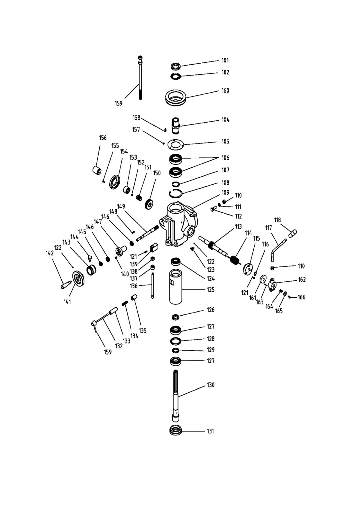

Part
Description
Part
Description
101
Nut
132
Lock Knob Shaft
102
Washer
133
Lock Block (L)
103
****
134
Spring
104
Spline Shaft
135
Lock Blocks (S)
105
Bearing Cover
136
Screw
106
Bearing 6209ZZ
137
Lock Nut
107
S-Ring 45
138
Height Nut
108
C-Ring 85
139
Block
109
Head Casting
140
M5-15 Pan Head Screw
110
1/2" Nut
141
Handwheel
111
1/2" Lock Washer
142
Handle
112
1/2" - 1½" Screw
143
Stepped Sleeve
113
Gear Shaft
144
Dial Positioning Screw
114
Spring
145
9/16" Nut
115
Flange Cover
146
Bearing 51102
116
S-Ring 19
147
Sleeve
117
Handle Lever
148
5x5x20 Key
118
Knob
149
Worm Shaft
119
M8-25 Cap Screw
150
Coupling Worm Gear
120
Handle Base
151
Spring
121
M5-16 Cap Screw
152
6x6x15 Key
122
M6-8 Set Screw
153
Coupling
123
Oil Cup
154
Plate
124
Bearing 6206ZZ
155
M5-10 Pan Head Screw
125
Spindle Quill
156
Knob
126
Nut
157
M5-8 Pan Head Screw
127
Bearing 7207
158
Key
128
Bearing Washer (B)
159
Lock Handle
129
Bearing Washer (S)
160
Spindle Pulley
130
Spindle
161
Space
131
Spindle Nut


Part
Description
Part
Description
201
5x5x40 Key
221
****
202
****
222
****
203
M6-8 Set Screw
223
****
204
****
224
****
205
M8x-20 Cap Screw
225
Lower Belt Cover
206
M8 Washer
226
M6-35 Screw
207
Motor
227
M6 Washer
208
M16-75 Screw
228
Latch
209
M16 Nut
229
M3-8 Pan Head Screw
210
Bracket
230
M5-8 Pan Head Screw
211
1/2" - 1½" Screw
231
M5 Nut
212
1/2" Lock Washer
232
Cover Supporting Arm
213
1/2" Nut
233
M5-10 Pan Head Screw
214
1/2"- 1¾" Screw
234
Cover Hinge
215
Mounting Plate
235
****
216
Pivot
236
****
217
Vertical Head Adaptor
237
****
218
Upper Belt Cover
238
Belt B-59
219
Knob
239
Motor Pulley
220
****
240
M5 Washer


Part
Description
Part
Description
301
Handle
326
M5-30 Pan Head Screw
302
5/8" Nut
327
Adjsuting Screw
303
M6-8 Set Screw
328
Handle Bar
304
Handle
329
Table Locking Screw
305
Dial
330
M6-16 Cap Screw
306
Dial Positioning Screw
331
M5 Nut
307
M6-25 Cap Screw
332
M5-10 Ppan Head Screw
308
Spacer
333
Rubber Sheet
309
S-Ring 20
334
Gib
310
Bearing 6004ZZ
335
M5-25 Cap Screw
311
M6-45 Cap Screw
336
Limit Seat
312
Lead Screw Bracket (R)
337
Cross Nut
313
5x5x20 Key
338
M8-25 Cap Screw
314
Long Leadscrew
339
Saddle
315
M6-8 Pan Head Screw
340
Stop Block
316
Rubber Sheet
341
M5-20 Pan Head Screw
317
Rubber Sheet Holder
342
Longitudinal Nut
318
Table
343
M6 Washer
319
Star Washer
320
Bearing 6004ZZ
321
M10-30 Screw
322
Adjsuting Screw Sleeve
323
M10 Nut
324
Gib
325
Limit Block


Part
Description
Part
Description
401
****
434
Bearing Housing
402
****
435
Cross Leadscrew
403
Column
436
Bearing 6204zz
404
Lamp Assembly
437
Leadscrew
405
M6-8 Cap Screw
438
Pedestal
406
Gib
439
Cover
407
Lock Screw
440
Holder
408
Oil Joint
441
Machine Base
409
Knee
442
Cover
410
Knee Cover
443
Limit Block
411
M3-6 Pan Head Screw
444
Limit Track
412
Handle Bar
445
M10-30 Screw
413
Oil Pump
446
Sleeve
414
M5-15 Pan Head Screw
447
M10 Nut
415
Nut
448
M6-30 Screw
416
Tab Washer
449
1/2" - 2" Screw
417
Bevel Gear
450
1/2" Lock Washer
418
Bearing 6004ZZ
451
10x20 Pin
419
Gear Shaft Sleeve
452
****
420
M6-16 Cap Screw
453
3/16" - 1/2" Pan Head Screw
421
5x5x20 Key
454
Column Cover
422
Gear Shaft
455
M6-8 Pan Head Screw
423
S-Ring 20
456
Cable
424
Coupling
457
Strain Relief
425
M6-8 Set Screw
458
3/16" - 3/4" Pan Head Screw
426
Dial Positioning Screw
459
Cable (3)
427
Dial
460
3/16" Nut
428
Crank Arm
461
Contactor
429
S-Ring 18
462
Cable (4)
430
Handle Bar
463
Bus Bar
431
Handwheel
464
Mounting Track
432
Dial
465
AC Motor Controller
433
Bearing 51104


Part
Description
Part
Description
P01
Set Nut
501
M5-15 Pan Head Screw
P02
Dial
502
Nozzle Hose
P03
M6-25 Cap Screw
503
Pipe Union
P04
Power Feed
504
Hose
P05
3x3x30 Key
505
Splash pan
P06
Stop W/Plunger Assembly
506
M6-8 Pan Head Screw
P07
Auto Stop Switch
507
M6-15 Pan Head Screw
P08
M6-16 Pan Head Screw
508
M6 Washer
P09
M6 Washer
509
Pump Motor
P10
Transformer
510
Pump Cord
511
Kettle
512
Switch


Table of contents
Other CHESTER Power Tools manuals


Popular Power Tools manuals by other brands

TOOLCRAFT
TOOLCRAFT T-HLP 2000 W operating instructions

HIKOKI
HIKOKI CV 12DA Handling instructions

Black & Decker
Black & Decker SZ360T instruction manual

Bosch
Bosch GST 25 Metal Professional Original instructions

Electronica Technologies
Electronica Technologies EL700 manual

Mafell
Mafell DD40G Original operating instructions


Parkside
Parkside PDSP 1000 E6 Translation of the original instructions

Euro Shatal
Euro Shatal RP3014E-50 Operating instructions and spare parts list

Makita
Makita DSC163ZK instruction manual

Makita
Makita DJV140 instruction manual

Porter-Cable
Porter-Cable 7539 instruction manual

ABB
ABB ACS560 Hardware manual