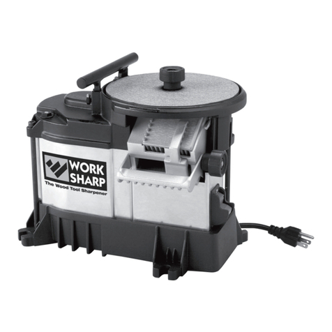
Work Sharp WS3000 User manual

GUÍA DEL USUARIO MODE D'EMPLOI
Fast, Precise, Versatile Wood Tool Sharpening
Afilado rápido, preciso y versátil de herramientas para madera
Affûtage d’outils à bois rapide, précis et polyvalent

A Message from the President of DAREX
DAREX, LLC
DAREX,
I am equally proud of the great people
at DAREX, LLC who are dedicated to designing, marketing, and manu-
facturing great products.

www.worksharptools.com 3
!IMPORTANT
Safety Warnings & Precautions
For your own safety, please read this User’s Guide before operating
WORK SHARP®The Wood Tool Sharpener
Installation / Assembly
• Carefully unpack WORK SHARP®The Wood Tool Sharpener and set it
on a table or workbench. Check to see that no damage has occurred
in shipment. Check all packing material to be sure that all parts are
present. See User’s Guide page 6 for part identification diagram.
• The WORK SHARP®unit needs to be placed on a flat stable tabletop
to complete assembly.
• Connect to properly wired outlet, or electrical shock may occur.
Precautions
FIRE CAN CAUSE DEATH, INJURY AND PROPERTY DAMAGE!
Reduce the risk of death, injury or property damage from fire. Read,
understand and follow these safety instructions. Make certain that any-
one else who uses this sharpener or who is a bystander in the sharp-
ening area understands and follows these safety instructions as well.
Remember, sharpening produces sparks and hot metal debris that can
start fires, burn skin and damage eyes.
ELECTRIC SHOCK CAN KILL! Reduce the risk of death or serious
injury from shock. Read, understand and follow these safety instruc-
tions. Make certain that anyone else who uses this sharpener or who
is a bystander in the sharpening area understands and follows these
safety instructions as well.
SHARPENING DEBRIS CAN INJURE EYES AND BURN SKIN! Re-
duce the risk of injury from sharpening debris. Read, understand and
follow these safety instructions. Make certain that anyone else who
uses this sharpener or who is a bystander in the sharpening area un-
derstands and follows these safety instructions as well.
ELECTRIC SHOCK
WARNING Electric Shock Can Kill! Read, understand and follow ALL
Safety instructions.
• AVOID BODY CONTACT WITH EARTHED OR GROUNDED
SURFACES (e.g., pipes, radiators, ranges, refrigerators).
• DO NOT ABUSE THE CORD. Never yank the cord to disconnect it
from the socket. Keep the cord away from heat, oil and sharp edges.
Do not modify the electrical plug provided—if it will not fit the out-
let, have the proper outlet installed by a qualified electrician.
• USE PROPER EXTENSION CORD. Use only 3-wire extension cords
that have 3-prong grounding plugs and 3-pole receptacles that ac-
cept the tool’s plug. Make sure your extension cord is in good condi-
tion. When using an extension cord, be sure to use one heavy enough
to carry the current your product will draw. Please refer to the fol-
lowing table for minimum cord size requirements:
• DISCONNECT TOOLS. Always disconnect WORK SHARP®unit
when cleaning, inspecting, and changing accessories. When not in
use, disconnect from the power supply. Never touch internal parts of
the sharpener when it is turned on or plugged in.
Ampere Rating Volts
More Not More
Than Than 120v 25 ft. 50 ft. 100 ft. 150 ft.
AWG
0 6 18 16 16 14
18" minimum
flammable
materials
FIRE PREVENTION
Sharpening operations create hot sparks
and sharpening debris:
1. The work area must be kept clean and free from all
flammable material.
2. The workbench should be protected with an appropriate
heat resistant cover to prevent fire or scorching of surfaces.
3. Keep an approved fire extinguisher of the proper size
and type in the work area. Inspect it regularly to ensure
that it is in proper working order. Know how to use the
fire extinguisher.
4. WARNING: NEVER perform sharpening operations in
the presence of flammable liquids or gasses.

4www.worksharptools.com4www.worksharptools.com
• GROUNDING INSTRUCTIONS: In the event of a malfunctions or
breakdown, grounding provides a path of least resistance for electric
current to reduce risk of electric shock. This tool is equipped with an
electric cord having an equipment-grounding conductor and ground-
ing plug. The plug must be plugged into a matching outlet that is
properly installed and grounded in accordance with all local codes
and ordinances. Improper connection of the equipment-grounding
conductor can result in a risk of electric shock. The conductor with
insulation having an outer surface that is green with or without yel-
low stripes is the equipment-grounding conductor. If repair or re-
placement of the electric cord or plug is necessary, do not connect
the equipment-grounding conductor to a live terminal. Check with
a qualified electrician or service personnel if the grounding instruc-
tions are not completely understood, or if in doubt as to whether the
tool is properly grounded. Repair or replace damaged or worn cord
immediately
• THIS TOOL IS INTENDED FOR USE ON A CIRCUIT THAT HAS AN
OUTLET THAT LOOKS LIKE THE ONE ILLUSTRATED IN FIGURE
A. The tool has a grounding plug that looks like the plug illustrated
in figure A. A temporary adapter, which looks like the adapter il-
lustrated in figures B and C, may be used to connect this plug to a
2-pole receptacle as shown in figure B if a properly grounded outlet
is not available. The temporary adapter should be used only until a
properly grounded outlet can be installed by a qualified electrician.
The green-colored rigid ear, lug, and the like, extending from the
adaptor must be connected to a permanent ground such as a properly
grounded outlet box.
PERSONAL PROTECTION
Sharpening operations can create hot sparks and metal debris, loud
noises and dust.
• ALWAYS USE SAFETY GLASSES. Everyday eyeglasses only have
impact resistant lenses, they are NOT safety glasses.
• USE EAR PROTECTION DURING USE. WORK SHARP®unit can
generate in excess of 85 dB(A) noise emissions under certain load
conditions.
• Use face or dust mask if working operations create dust.
• WEAR CLOSED, NON FLAMMABLE PROTECTIVE CLOTHING. Do
not wear loose clothing, gloves, neckties, rings, bracelets, or other
jewelry which may get caught in moving parts. Wear protective hair
covering to contain long hair
•KEEP WORK AREA CLEAN. Cluttered areas and work benches in-
vite accidents.
•FREQUENTLY CLEAN SHARPENING DEBRIS FROM UNIT AND
WORK AREA.
•DO NOT USE IN DANGEROUS ENVIRONMENT. Do not use in damp
or wet locations, avoid exposure to rain. Keep work area well lit. Do
not use tools in the presence of flammable liquids or gases.
•KEEP CHILDREN AWAY. All visitors should be kept safe distance
from work area, do not let persons not involved in the work touch the
tool or power cord.
•MAKE WORKSHOP KID PROOF with padlocks, master switches, or
by removing starter keys.
•SECURE WORK. Use clamps or a vise to hold work when practical.
It’s safer than using your hand and it frees both hands to operate the
tool.
•DO NOT FORCE THE TOOL. It will do the job better and safer at the
rate for which it was intended.
•USE THE RIGHT TOOL. Don’t force tool or attachment to do a job
for which it was not designed. Don’t force small tools to do the job of
a heavy duty tool. Do not use the tool for purposes not intended.
•NON-SLIP FOOTWEAR IS RECOMMENDED.
•NEVER LEAVE TOOL RUNNING UNATTENDED. Ensure tool has
come to a complete stop before leaving work area.
•MAINTAIN TOOL WITH CARE. Keep WORK SHARP®unit clean for
best and safest performance. Follow instructions for maintenance
and changing accessories. Inspect cords periodically and if damaged
have them repaired by an authorized service facility. Inspect exten-
sion cords periodically and replace if damaged. Keep unit dry, clean
and free from oil and grease.
•STORE IDLE TOOLS. When not in use, tools should be stored in a
dry, locked-up place out of the reach of children.
•AVOID UNINTENTIONAL STARTING. Make sure switch is in the
“OFF” position before plugging in.
•STAY ALERT. Watch what you are doing, use common sense and do
not operate the tool when you are tired or impaired.
•DON’T OVERREACH. Keep proper footing and balance at all times.
•NEVER STAND ON TOOL. Serious injury could occur if the tool is
tipped or if the cutting tool is unintentionally contacted.
Fig. A
Fig. B
Fig. C

techsupport2@darex.com
DAREX, LLC

6www.worksharptools.com6www.worksharptools.com
1Getting to Know
Your Tool
WORK SHARP®
The Wood Tool Sharpener & Hone
2" Sharpening Port
and Heat Sink
T-Slots for mounting
accessories
Top Knob
6' Power Cord
Motor
1⁄5horsepower induction
Wheel Speed
580 RPM (gear reduced)
Wheel Material
150mm tempered float glass
Tool Construction
Cast-aluminum top; sheet-metal housing; impact and vibration-resistant, tool-grade plastic base
Cooling System
Heat sink with routed airflow
Power Connection
Industrial grade switch with safety lockout; grounded 6' power cord
Abrasives
150mm and 2" premium, durable PSA (Pressure Sensitive Adhesive) ceramic oxide and aluminum oxide
abrasives (Also accepts standard 6" abrasives. Trimming is required to fit 150mm tempered glass wheel.)
Honing
150mm Micro-Mesh™ 3600 cushioned abrasive (6 µ micron)
(Leather disk and honing compound accessory available.)
Tool Specs
Hub
Angle Indicator
Wheel Shroud
T-Slots for mounting
accessories
Locking
Power Switch
Bevel Angle
Selection Lever
Skew Cam
Adjustment Lever
Fence Adjustment
Knob
Wheel Direction
Indicator
Sharpening
Port Fence
Bench Mounting
Tabs
Bench Mounting
Tabs
Tempered Glass
Wheel
Underside Port
Tool Rest
OFF-LOCKED OUTOFF
ON
To lock out power switch, remove the lock-out key. The machine
can now be turned off, but not on.
To turn the machine on, insert lock-out key in the front of the
power switch. Machine may now be turned on or off.

www.worksharptools.com 7
WORK SHARP®Wood Tool Sharpener Component Checklist
PSA Abrasive Kit includes:
150 mm PSA Abrasive to be adhered to
the tempered Glass Wheels:
•P120 (127µ) Ceramic Oxide
•P400 (35µ) Aluminum Oxide
•P1000 (18µ) Aluminum Oxide
•Micro Mesh 3600
2"×2" PSA Abrasive for the
heat sink/lapping surface:
• 400x (35µ) Ceramic Oxide
Standard Kit includes:
Top Knob
Top Tool Rest
and Hardware (2
thumbscrews)
2 tempered Glass
Wheels
User’s Guide
Additional Abrasives
Edge-Vision™ Slotted Wheel
Crepe Stick
USER’S GUIDE
Fast, Precise, Versatile Wood Tool Sharpening
ENGLISH ESPAÑOL FRANÇAIS
Micro-Mesh™ 3600
cushioned honing abrasive,
equivalent to 6µ (micron)
PSA (Pressure Sensitive Adhesive)
Abrasive Kit
2Available
Accessories
Edge-Vision™ Slotted Wheel
#WSSA0002029
Tempered Glass Wheel
#WSSA0002023
Leather Honing Wheel with Compound
#WSSA0002001
150mm leather disk adhered to a 150mm tempered glass
wheel (Chromium oxide honing compound included)
Abrasives Kit: Slotted
#WSSA0002002
1 pc. P80 slotted, 2 pcs. P400 slotted, 2 pcs. P1200
slotted, 1 pc. 150mm Micro-Mesh™ 3600 slotted
Abrasives Kit: Coarse
#WSSA0002005
2 pcs. 150mm P80, 2 pcs. 150mm P120,
3 pcs. 150mm P220, 2 pcs. 2" P400
Abrasives Kit: Micro-Mesh™ Honing Kit
#WSSA0002044
1 pc. 150mm 3600 Micro-Mesh™,
1 pc. 150mm 6000 Micro-Mesh™
Abrasives Kit: Fine
#WSSA0002043
4 pcs. 150mm P400, 6 pcs. 150mm P1000,
2 pcs. 2" P400

8www.worksharptools.com8www.worksharptools.com
3Assembling
Your Tool
1. Carefully remove the tool and the accessories kit from the box.
2. Refer to Component Checklist (page 7) to ensure that you have
received all the components, including Abrasives.
3. Remove all packing materials and store in case you ever need to
return the unit for servicing.
4. Visually inspect your tool for potential damage incurred during
shipment. If there is damage, call 800-597-6170 to speak to a Cus-
tomer Service Representative.
5. Apply PSA Abrasive. A clean work environment is critical during
the adhesion of the PSA Abrasive. Unpack and clean the tempered
Glass Wheels with isopropyl alcohol, paint thinner or acetone to en-
sure a clean surface to adhere the PSA Abrasives. Mineral spirits is
not recommended since it leaves an oily residue.
The 2 tempered glass wheels provided are intended to have a dif-
ferent abrasive grit on each surface. This allows you to have a coarse
grinding wheel for shaping and sharpening and a fine grinding wheel
for honing.
To apply the chosen 150 mm Abrasive to a Glass Wheel surface,
simply peel the backing off the abrasive disk. Handle the Abrasive
disc by the outer edges, being careful not to get any contaminants
on the PSA backing as they will produce lumps under the paper and
decrease sharpening performance. Flex the paper into a “U” shape so
the center of the Abrasive is centered on the Glass Wheel. See fig.
3-1. Slowly flatten out the Abrasive from the center working toward
the outer edge of the Glass Wheel. For best results, roll a dowel
over the Glass Wheel after adhering the Abrasive to remove any air
bubbles that have formed. If air bubbles remain under the PSA Abra-
sive after rolling, pierce them with a needle or fine knife point and
then press them firmly to remove the air.
Your WORK SHARP®also includes an Edge-Vision™Slotted
Wheel for see-through sharpening of radius tools using the Under-
side Sharpening Port. The corresponding slotted Abrasive is specifi-
cally designed for this Wheel. Make sure all the slots in the abrasive
properly align with the slots in the wheel surface. This will ensure
proper performance of the Edge-Vision™Slotted Wheel during use.
Sharpening Port PSA Abrasive adhered to the heat sink.
The 2" × 2" P400 PSA Abrasive is adhered to the heat sink at the
manufacturer. The abrasive in the
Sharpening Port laps the back of a
tool during sharpening. This signifi-
cantly decreases the burr, or wire,
during sharpening and dramatically
reduces sharpening time.
An extra piece of this abrasive
has been provided for you. To re-
place this Abrasive to the heat sink,
the Fence must first be moved all the way to the left of the Sharpen-
ing Port, and the wheel must be removed. To traverse the Fence to
the left, simply roll the Fence Alignment Knob toward yourself. Keep
traversing the Fence to the left side of the Sharpening Port until it
passes the notched wall on the left side and stops. Do not force the
Fence Alignment Knob or Fence. Once the Fence is completely on
the left side of the Sharpening Port, (See fig. 3-2.) peel the backing
off the 2" × 2" P400 PSA abrasive. Handle the Abrasive by the outer
edges, being careful not to get any contaminants on the PSA backing
as they will produce lumps under the paper and decrease sharpening
performance. You will have to slide the Abrasive under the Wheel
Shroud. Be sure that the Abrasive fits squarely on the heat sink
and that the upper edge of the Abrasive (closest to the center of the
Wheel Hub) fits right to the edge of the heat sink. See fig. 3-3.
6. Place the tempered Glass Wheel with coarse abrasives onto the
Wheel Hub. Mount the Wheel so the coarser side of the Glass Wheel
is facing up. Secure the Wheel with the provided Top Knob. Do not
over-tighten the Top Knob; it only needs to be finger tight.
7. Install the Top Tool Rest. To install your Top Tool Rest, first re-
move it from the packaging and locate the 2 provided thumbscrews
to mount the Tool Rest. Simply slide the Top Tool Rest into the T-
Slots on the top of the unit. See fig. 3-4. Thread the provided fas-
teners into the tapped holes in the Tool Rest. Ensure the Tool Rest
is level by placing a level on top of the Tool Rest surface. Once you
have located the height and level of the Tool Rest you wish, tighten
the 2 thumbscrews to secure the Tool Rest. Do not over-tighten these
2 thumbscrews, as you can potentially stress and/or damage the T-
Slots in the top casting.
Fig. 3-1
Fig. 3-2
Fig. 3-3
Fig. 3-4

www.worksharptools.com 9
4Quick Start
Guide
This is intended as a brief introduction or refresher on the use of your
tool, please read the following sections in their entirety before first use
of the WORK SHARP®The Wood Tool Sharpener.
STEP 1
Determine tool type and desired sharpening angle: 20°, 25°, 30°
or 35°.
•Chisels and plane irons up to 2" are sharpened in the Sharpening
Port.
•Wider tools are sharpened freehand on top of wheel surface using
the Top Tool Rest.
•Carving and lathe tools are sharpened using the Edge-VisionTM
Slotted Wheel.
STEP 2
Set the angle of the Sharpening Port to the desired angle.
To change Sharpening Port angles, place your thumb on the heat sink,
while grasping the Bevel Angle Adjustment Lever with your fingers.
See fig. 4-1. Squeeze thumb and fingers together to release spring
loaded tooth engagement. Move Port up or down to change angles.
Look on the right side of Sharpening Port next to the Fence Alignment
Knob to reference the angle selected.
STEP 3
Assure that you have the proper grit selected and installed on the
Sharpener. Please refer to “Selecting the Right Abrasive for the Job”
(p. 10) for more information concerning grit selection.
STEP 4
Flatten tool back on top of wheel using a two-handed, freehand
method. IMPORTANT: Lay tool onto Abrasive heel first. Do not grind or
round off the cutting edge! See fig. 4-2.
STEP 5
Place tool to be sharpened back down (bevel facing up) in the
Sharpening Port onto the lapping Abrasive.
STEP 6
Move Fence lightly against tool using the Fence Alignment Knob
on right side of port. Leave Fence loose enough for tool to slide be-
tween Fence and guide rail. See fig. 4-3.
STEP 7
Slide tool (bevel up) into Sharpening Port between Fence and guide
rail. See fig. 4-4. Contact Wheel for 1–2 seconds (no longer), then pull
tool away from the Wheel, being sure to keep the back of the tool flat
on the lapping Abrasive. It is important to pull the cutting edge at least
halfway down the lapping Abrasive to remove any burr that may have
been created. Repeat this plunge and pull process approximately 10
times until damage to the cutting edge has been removed and a consis-
tent finish is attained.
STEP 8
Repeat this plunge and pull process using finer grit selections until
the tool has reached desired finish or sharpness. For optimum finish
use all grits provided. Final hone and micro bevel if desired.
Plunge Pull
Fig. 4-1
Fig. 4-2
Fig.4- 3
Fig. 4-4

10 www.worksharptools.com10 www.worksharptools.com
5Selecting the Right
Abrasive for the Job
About WORK SHARP™Abrasive Technology
Finish
•Coated abrasive disks start flat and stay flat. (Bonded abrasives used
in stones and most power systems require frequent dressing to keep
the wheel flat.)
•Heat treated aluminum oxide and ceramic abrasives provide a pol-
ished finish superior to oil and water stones without the mess.
•Premium P-graded Abrasives provide more consistent cutter height
and smoother surface finish than traditional bonded and plated abra-
sives. (As bonded wheels wear they tend to round the edges/corner
of the tool. As the abrasive particles wear, the bond breaks down,
exposing new particles but always at a different depth.)
•The grit size is engineered to provide optimal sharpness and surface
finish at each stage of sharpening. (Users who are interested in a
“utility sharp” edge will find exceptional edge performance on the
faster coarse grits without the need to hone.)
Speed
•The abrasive selection is integrated with design of the WORK
SHARP®drive train and cooling system to provide the fastest materi-
al removal rate while minimizing the risk of overheating tool steels.
•The sharpening port includes a lapping abrasive that provides supe-
rior burr control and allows for 1-step re-sharpening.
•Two-sided wheel and off-the-shelf abrasive makes it easy to switch
between coarse and fine abrasives. (Doesn’t require re-grading the
wheel just to switch between coarse and fine Abrasives. Doesn’t re-
quire an expensive selection of custom wheels or disks.)
Simplicity
•Accepts standard 150 mm or 6" PSA-backed adhesive that is read-
ily available. (No custom adhesives or expensive custom wheels re-
quired. Coarse grits are available at most hardware/woodworking
stores. Fine grits are readily available at any automotive paint sup-
ply store.)
•Abrasive disk life can be extended significantly by regular cleaning
using the supplied disk cleaner (Crepe Stick). Simply rub the Crepe
Stick across the surface of the Wheel to remove any loading or build-
up on the Abrasive.
CAMI (USA)
Individual Mesh
FEPA (Europe)
“P”
Micro Mesh Micron
µ
80 P80 197
100 141
120 P120 127
P150 97
150 93
180 P180 78
220 66
P220 65
P240 58
240 53
P280 52
P320 46
280 44
P360 40
320 36
P400 35
P500 30
360 28
P600 25
400 1500 23
P800 21
500 P1000 18
600 1800 16
P1200 15
800 P1500 12
2400 11
P2000 10
1000 9
P2500 8.5
1200 3200 6.5
1350 3600 6
1500 4000 3
6000 2
8000 1.2
P120 equivalent to 127 µ (micron) for use with damaged or chipped
tools
P400 equivalent to 35 µ (micron) for use with nearly sharp tools
which only require a touch-up
P1000 equivalent to 18 µ (micron) for use when fine sharpening the
tool
Micro-
Mesh™
3600
equivalent to 6 µ (micron) for use when honing the tool
Ceramic Aluminum
Oxide Benefits Oxide Benefits
•Fastest cut rate •Fast cut rate
•Cool cutting •Consistent finish
•Longest life •Increased life
•Maximum load resistance •Reduced loading

www.worksharptools.com 11
6Sharpening
Straight-Edged Tools
☛ Master Tip: Sharpen even new tools
It is imperative to sharpen a new tool before use. Most manu-
facturers only rough grind a tool and do not properly flatten
the back or hone the primary bevel angle. The entire back does
not need to be flat, only the third of the chisel back from the
cutting edge to the handle needs to be flat. See fig. 6-2. Once
this is done to a new tool, it does not need to be done again, un-
less the tool has become damaged or you have sharpened past
the third of the back you have already flattened. For best tool
performance and ease of use, a new tool must be sharpened to
achieve a flat back and keen bevel edge. New tools often come
coated in lacquer, or some type of hardened protective coat-
ing. For best results, remove this coating with paint or lacquer
thinner before sharpening. This will keep your Abrasives from
loading up and needing premature replacement.
☛ Master Tip
Be sure to lay the tool down heel first and not cutting edge
first on the right side of the wheel. This will ensure that you do
not grind material away from the tool back at the cutting edge,
which makes it very difficult to sharpen to a keen edge. If you
do accidentally remove material from the chisel back at the
cutting edge, you must continue to grind the tool back flat until
the damage is removed. It may take a long time to perform this
task, but it is crucial to achieving a keen cutting edge.
STEP 1 •Flatten the tool back
Mount your coarse
Abrasive Wheel with
P120 face up to flatten
the chisel or plane iron
back. Turn on the unit
and use the freehand
method to flatten the
tool back by carefully
placing the tool back
onto the right side of
the wheel (so the wheel
is spinning away from
you). See fig. 6-1.
STEP 2 •Sharpen the primary bevel
The WORK SHARP®unit has the ability to sharpen precise and repeat-
able bevel angles of 20°, 25°, 30° and 35°. To change Sharpening Port
angles, place your thumb on the heat sink while grasping the Bevel
Angle Selection Lever with your fingers. Squeeze thumb and fingers
together to release spring-loaded tooth engagement. See fig. 6-3. Pull
Sharpening Port all the way up to get a 20° bevel angle, move down
one click for a 25° bevel angle. Move down two clicks for a 30° bevel
angle, and all the way down to the bottom for a 35° bevel angle. Re-
lease thumb and finger squeeze to engage teeth to hold selected angle.
Look through the Bevel Angle Se-
lection Window on the right side of
Sharpening Port next to the Fence
Alignment Knob to reference the
angle selected.
Once you have selected the
desired Sharpening Port angle,
you can proceed to fit the tool into
the Sharpening Port. To do so, lay
the tool to be sharpened into the
Sharpening Port back down (bevel
up) so that it lies flat on the heat
sink surface. The Sharpening Port
offers a guide rail on each side and
also an Adjustable Fence to ensure
a square bevel grind.
Tools under ½" wide can be sharpened on the left side of Port,
while tools wider than ½" should be sharpened on the right side of
the Port. See fig. 6-4. This is due to the varying Wheel speed at differ-
ent surface points. The center of the Wheel has a slower surface speed
and is less likely to overheat a smaller tool.
Once the tool is placed on the proper side of the Port, move the
Fence lightly against tool using the Fence Alignment Knob. See fig.
6-5. Leave the Fence just loose enough for the tool to slide between
the Fence and guide rail. Slide tool (bevel up) into the Sharpening Port
between the Fence and guide rail and contact the Abrasive Wheel for
1–2 seconds (longer will only produce more heat and a large burr wire).
Pull the tool away from the Wheel no less than one inch, while keep-
Unlapped
Lapped
Fig. 6-1
Fig. 6-2
Fig. 6-3
Fig. 6-4
Fig. 6-5

12 www.worksharptools.com12 www.worksharptools.com
ing it flat and square on the lapping Abrasive in the Sharpening Port.
This is a critical step since the lapping Abrasive on the heat sink
removes the burr wire. The best sharpening method is to repeatedly
‘plunge and pull’ the tool in the Sharpening Port. See fig. 6-6. This
not only minimizes heat build up in the tool being sharpened, but also
assists in removing the burr wire edge when you pull the tool back
across the lapping Abrasive in the Sharpening Port. Using this plunge
and pull method will yield a keen sharp edge the fastest. Once the tool
back and primary bevel have been completely sharpened (the entire
surface has an even grind finish), turn unit off and change Abrasive
Wheel to a finer grit. Repeat same sharpening steps on finer grits to
remove scratches from previous coarser grit grinding. Continue sharp-
ening all the way up to the finest grit to achieve sharpest results.
☛ Master Tip: Create a micro bevel
If you desire, you can now sharpen your tool to have a micro
bevel. See fig. 6-7. Generally, a micro bevel is sharpened onto
a cutting tool to minimize the amount of time
it takes to re-hone the cutting edge after use,
and to provide a stronger cutting edge. As an
additional benefit, a micro bevel will extend
the life of your Abrasives since you will be
re-sharpening a much smaller area each time.
Use the following micro bevel angle guide to
create a micro bevel quickly and easily:
•Use your P1000 Abrasive Wheel surface
face down to sharpen the micro bevel
•You only have to contact the wheel very
briefly to create the micro bevel
•If you sharpened to 20°, micro bevel in the
Sharpening Port at 25°
•If you sharpened to 25°, micro bevel in the
Sharpening Port at 30°
•If you sharpened to 30°, micro bevel in the
Sharpening Port at 35°
STEP 3 •Re-sharpening a tool
The steps to re-sharpen a tool are fundamentally the
same as the instructions outlined above for a new
tool. The differences are that you may not need to flatten the tool back
again, depending on the damage, and you will not need to start your
sharpening on the coarse grits. If the tool is not visibly chipped or dam-
aged, start with the fine Abrasive Wheel. Or, if you have sharpened a 5°
micro bevel on your tool as outlined above, you only need to re-sharpen
the micro bevel on the P1000 abrasive surface. If the tool is chipped or
damaged, start sharpening with a coarser grit for fastest results.
STEP 4 •Honing the Tool
Honing chisels, plane irons, etc.
Micro-Mesh™ 3600 is a cushioned silicone carbide abrasive that pro-
vides a superior finish to tool steel. The provided Micro-Mesh™ honing
disk is the equivalent of 6µ (micron). For best results, sharpen your
tool with the provided abrasives of at least P400 and then P1000 and
ensure that the surface finish is clean, even and smooth after sharpen-
ing on the P1000 disk.
To hone the bevel of your tool, mount the Micro-Mesh™ honing disk
face down and turn the tool on. Repeatedly plunge and pull the tool to
the desired angle in the Sharpening Port. Continue bevel honing until a
consistent finish is achieved.
To hone the back of your tool, mount the Micro-Mesh™ honing disk
face up on the WORK SHARP®The Wood Tool Sharpener. Firmly grasp
the tool to be honed and place the back of the tool (heel first) onto the
right side of honing surface so the wheel is turning away from you.
Briefly contact the honing surface with your tool back and check for
finish. Continue honing until desired finish is achieved.
Honing carving and lathe tools
Sharpen your carving and lathe tools using the slotted see through
wheel and underside sharpening port. To sharpen a carving or lathe
tool, mount the slotted wheel with the abrasive side face down. Turn
the unit on and place the tool to be sharpened under the wheel in the
underside sharpening port on the back side of the unit. As the wheel
spins, look down through the wheel to see the tool to be sharpened.
Slowly and carefully bring the tool to be sharpened up to the wheel
surface. You should now be able to see the exact point of contact where
the abrasive disk is contacting the tool. Sharpen the entire heel of the
tool until a consistent finish is achieved. Now move the tool so the point
of sharpening contact is at the cutting edge. Continue sharpening or
honing until desired finish or sharpness is attained.
Optional Honing Accessories for
your WORK SHARP®sharpener
•The WORK SHARP®Leather Hone Accessory Kit comes with a
150mm premium leather disk attached to a tempered glass wheel
and Chromium Oxide honing compound.
•The WORK SHARP®Honing Media Accessory Kit comes with PSA-
backed Micro-Mesh™ 3600 (6µ micron) and Micro-Mesh™ 6000 (2µ
micron).
•The WORK SHARP®Slotted Media Accessory Kit comes with a
slotted piece of Micro-Mesh™ 6000 that will fit directly onto your
Slotted Wheel. This will allow you to hone your tools to a mirror fin-
ish using the see-through Slotted Wheel.
Plunge Pull
Fig. 6-6
Fig. 6-7

www.worksharptools.com 13
STEP 1 •Mount Top Tool Rest
Mount the Top Tool Rest as shown on pages 7–8.
STEP 2 •Select Top Tool Rest height to
determine angle
The height of the Tool Rest above the wheel and the tool projection off
the Tool Rest determine the bevel angle sharpened. Lay the tool to be
sharpened across the Tool Rest and onto the Abrasive Wheel surface.
Be sure that the bevel is laying flat on the Abrasive Wheel surface.
Raise or lower the Top Tool Rest to find the proper bevel angle desired.
See fig. 7-1. Check the
Tool Rest for level by using
a common level. Once you
have located the desired
height and level of the tool,
tighten the 2 thumbscrews
to secure the Tool Rest. Do
not over-tighten.
STEP 3 •Sharpening
Once proper Tool Rest height and tool projection are determined, sim-
ply lay the tool on the right side of the Tool Rest and contact the Wheel
surface while the unit is turned on. Similar to the bevel grinding in-
structions for the Sharpening Port, start with a coarse grit Abrasive
Wheel for damaged tools or tools that need to be ground to new angles.
For tools that need to be sharpened, start with a finer grit Abrasive.
Please refer to “Selecting the Right Abrasive for the Job” (p. 10) for
more information concerning grit selection. Working on the right side
of the Tool Rest allows you to sharpen with the Wheel turning away
from you. This is the best position on the Tool Rest for optimum control
during sharpening. Sharpening in this manner also draws a burr wire
onto the edge of the tool, so you may need to touch the back of the tool
being sharpened onto the Abrasive Wheel surface to remove the burr
wire.
☛ Master Tip
Be careful not to grind too aggressively as it will generate heat
in the tool being sharpened. If the tool being sharpened is get-
ting warm to the touch, simply stop sharpening for a moment
until the tool cools down. This will help ensure against damag-
ing the tool steel.
7Freehand
Topside Sharpening
8
Underside Sharpening with
Edge-Vision
™
Slotted Wheel
The following instructions explain how to use the Edge-Vision™Slot-
ted Wheel to sharpen carving and lathe tools.
STEP 1 •Select the proper Abrasive
For carving tools
These tools should be sharpened using the provided Edge-Vision™
Slotted Wheel and abrasives, then final honed using the provided Mi-
cro-Mesh™ Hone Wheel. Caution: using too coarse of an Abrasive on
smaller tools may cause the tool to overheat. If a carving tool has dam-
age on the cutting edge or needs to be shaped to meet your needs, start
with a coarser abrasive wheel and sharpen until damage is removed or
desired geometry is achieved. Then proceed to a finer grit slotted media
to refine the cutting edge and surface finish. Use the Micro-Mesh™
hone to polish tool until desired finish is achieved.
For lathe tools
Lathe tools are more tolerant to coarse grinding and do not need to be
honed to a mirror finish. For these types of tools you can achieve work-
able sharp results using the coarser slotted Abrasives.
STEP 2 •Apply Slotted Abrasive to
Edge-Vision™ Slotted Wheel
If you have not already applied the Slotted Abrasive to the Edge-Vi-
sion™ Slotted Wheel, refer to the instructions on page 8. Standard 6"
abrasives can be used on the Edge-Vision™Slotted Wheel. Trimming
will be required.
STEP 3 •Mount the Edge-Vision™
Slotted Wheel
The Edge-Vision™Slotted Wheel mounts to the unit the same as the
tempered Glass Wheels. Always mount the PSA Abrasive face down.
With the slotted wheel safely mounted and the unit turned on, you
should be able to see through the slotted wheel clearly for sharpen-
ing carving and lathe tools underneath the wheel. A standard shop light
or spot light can also be used to shine on top of the slotted wheel during
use to aid in the visibility of the cutting edge.
STEP 4 •Freehand sharpening of radius
tools with the Edge-Vision™ Slotted Wheel
With the Edge-Vision™Slotted Wheel properly mounted, you can begin
sharpening your radius carving and lathe tools. Orient the machine so
that the back of the machine is facing you and turn the WORK SHARP®
unit power switch to the on position. Slowly and carefully approach
the WORK SHARP®unit with your tool to be sharpened and position
the tool. Looking down through the Edge-Vision™Slotted Wheel, you
should be able to see the tool to be sharpened. See fig. 8-1. Slowly
approach the wheel with the tool to be sharpened and place the heel of
the tool onto the abrasive surface. You should be able to see the exact
point of contact between the wheel and tool being sharpened as you
look down through the Edge-Vision™Slotted Wheel. Slowly and
carefully move the tool being sharpened on the abrasive so the entire
bevel heel is sharpened. Now carefully roll the surface being sharpened
up to the cutting edge.
Continue until the entire
cutting edge is sharp.
See fig. 8-2. Once the
tool has an edge you
are satisfied with, you
can stop sharpening.
You can also mount the
Micro-Mesh™ wheel to
hone a mirror polish on
your tools if you desire.
Fig. 7-1
Fig. 8-1
Fig. 8-2

14 www.worksharptools.com14 www.worksharptools.com
☛ Master Tip
Use a permanent marker to mark the edge of the tool you wish
to sharpen. As you sharpen, you will be able to see the marker
ink being removed by the Abrasive. When the ink is gone, your
tool is sharp.
STEP 5 •Honing the inner edge of
the bevel
After sharpening the beveled side of the radius tool, you will want to
remove the burr created on the inside edge of the tool. To do so you
can use either a very fine cone-shaped slip stone (available from any
woodworking supply store or catalog) or a dowel wrapped with a very
fine abrasive of at least P1000.
9WORK SHARP®
Wood Tool
Sharpener Maintenance
After sharpening only a few tools, sharpening debris will accumulate
on your workbench and also under the Glass Wheel. Grinding particles
will promote wear in the Sharpening Port and can potentially contami-
nate your finer grit Abrasives, so cleaning on a consistent basis can
add life to your machine and Abrasives. Before any maintenance or
cleaning is performed, be sure to unplug your WORK SHARP®Wood
Tool Sharpener.
Cleaning your WORK SHARP®Wood Tool
Sharpener
With the WORK SHARP®Wood Tool Sharpener unplugged, remove
the Glass Wheel to expose the top of the unit and Sharpening Port.
Brush the accumulated sharpening debris from the Wheel and Sharpen-
ing Port area into a disposable container. Remove dust particles with a
small, dry brush. Dispose of the container and grinding dust in a safe
and environmentally approved manner. With a dry cloth or soft brush,
clean the Sharpening Port area to remove any sharpening debris that
may have accumulated.
▲ Important Safety Tip
BE SURE GRIT IS NOT HOT OR GLOWING,
AS IT MAY START A FIRE!
Cleaning your PSA Abrasive during or after
sharpening
With the WORK SHARP®Wood Tool Sharpener plugged in and turned
on, use the provided Crepe Block to clean the Abrasive. Start in the cen-
ter of the Wheel on the right side (with the Wheel turning away from
you) and apply the Crepe Block with light pressure. Keeping constant
light pressure on the Wheel with the Crepe
Block, slowly pull the Crepe
Block to the outer edge
of the Wheel. See
fig. 9-1. Clean-
ing the Abrasive
frequently will not
only enable it to cut
faster and last lon-
ger, it will also keep
your work environ-
ment cleaner.
Determining if replacing the 150mm or 2"
Abrasive is required
The provided selection of Abrasives with the WORK SHARP®unit is
designed to give you the best sharpening performance available. We
have included long-lasting and cool-grinding ceramic oxide and alumi-
num oxide Abrasives that will provide you with long-lasting results.
However, it will wear out eventually. It may need to be changed if:
•When sharpening a tool, it takes noticeably longer to achieve sharp
results
•Abrasive is ‘loading up’ and is not able to be cleaned further
•There is a tear, wrinkle, or hole in the Abrasive
•Cross contamination has occurred from a coarser grit
•There is a bubble or lump under the Abrasive on the Glass Wheel
For best results, use the WORK SHARP®replacement abrasives kits.
WORK SHARP®recommends the type of ceramic and aluminum oxide
Abrasives we provide because they create a finish superior to oil and
water stones—without the mess. In addition, the grit size is engineered
to provide optimal sharpness and finish at each stage of sharpening.
However, if you choose, you can also use any standard 6" PSA
abrasive available at your local hardware store or tool distributor. Trim-
ming of standard 6” abrasives will be required to fit the 150mm tem-
pered glass wheels. Or, you can also use a standard 8" x 11" sheet of
your preferred sandpaper, and cut it to size. First spray the Abrasive
backing with a spray tack adhesive, then place the Glass Wheel onto
the paper. Trace and cut the wheel shape out of the sheet of sandpa-
per.
Contact the store or dealer where you purchased the WORK
SHARP®The Wood Tool Sharpener, or contact WORK SHARP®di-
rectly at www.worksharptools.com, to purchase replacement abra-
sive kits.
10 Troubleshooting
FAQ
Problem
Bevel edge not square
Solution
The bevel edge of the tool is skewed. You can
adjust the Skew Cam to compensate.
The WORK SHARP®unit has the ability to
fine tune the amount of skew sharpened onto
a tool at the bevel edge. The unit is factory set
to provide you with a square tool edge. If the
Square Skewed
Skew Cam
Adjustment Lever
Skew Cam
Set Screw
Fig. 9-1

www.worksharptools.com 15
Problem
Not sharpening entire bevel face
Solutions
• Not sharpening to the same bevel angle previously sharpened onto
tool.
• Sharpening not complete yet. Use coarse grit for fast material re-
moval.
• Tool being sharpened is not completely flat on the heat sink during
sharpening.
• Sharpening port fence is not snug against tool, which allows tool to
skew in port.
Problem
Excessive heat build-up
Solutions
• Leaving tool in sharpening port against abrasive disk too long.
• Applying too much load pressure against abrasive disk during sharp-
ening.
• Abrasive needs to be cleaned or replaced.
• Smaller tools should be sharpened on the left side of port using light
pressure and less sharpening time.
Lever Up
Raises the right side of Port
Lever Down
Lowers the right side of Port
Problem
Micro bevel on heel of bevel, not cutting edge
Solution
Wrong angle selected for micro bevel. You must micro bevel to a steeper
(larger) angle than your primary bevel to achieve a micro bevel. Ex-
ample, if you sharpened your chisel to a 25° bevel and attempted to
micro bevel at 20°, you will grind the heel of the bevel edge, not the
cutting edge. Reference micro bevel detail on page 12.
Problem
Sharpening Port fence feels too tight
Solution
The sharpening port fence is tight by design to prevent fence deflection.
However, sharpening debris may contaminate the port fence thread
surface and create excessive friction during use. Clean the exposed
thread surface with a soft brush to remove any grit or contamination.
If excessive friction still occurs, use only a small amount of oil or syn-
thetic lubricant spray to lubricate the thread surface. Do not over apply
any lubricant since it will only collect more sharpening debris and can
lead to premature thread wear.
Problem
Cannot get sharpening grit pattern removed from tool
Solutions
• You have skipped an abrasive grit in the sharpening process. Use
each grit provided for best results.
• You have not spent enough time on each grit during sharpening. En-
sure all grind marks from previous grit have been removed before
proceeding to the next finer grit.
• Abrasive needs to be cleaned or replaced.
Problem
Sharpening takes excessively long time
Solutions
• PSA Abrasive needs to be cleaned with the Crepe Stick or replaced.
• Tool being sharpened is excessively damaged and should be re-
ground or re-shaped using P120 Abrasive.
Problem
Excessive vibration
Solutions
• Glass wheel is damaged. STOP IMMEDIATELY and inspect glass
wheel for damage.
• WORK SHARP®unit not placed stably on work bench or work area.
Clamp to work bench with mounting tabs for best performance and
stability.
• If excessive vibration continues, call a customer service agent for
direction.
cutting edge on your tool is not perfectly square after sharpening, you
can adjust the Skew Cam on the Sharpening Port to return the Port to
square. (NOTE: The Skew Cam adjustment is not designed to create
or restore a skew chisel bevel edge. It is designed to allow adjustment
of the Sharpening Port to ensure square bevel edges.) To do so, follow
these simple steps:
STEP 1. Remove Glass Wheel from unit.
STEP 2. Locate Skew Cam Adjustment Lever and Screw Cam Set
Screw on right side of Sharpening Port.
STEP 3. Loosen Skew Cam Set Screw, do not remove.
STEP 4. Adjust Skew Cam Adjustment Lever according to amount of
skew desired.
STEP 5. Carefully hand tighten the Skew Cam Set Screw. Do not over-
tighten, as you may damage the thread surface in the top housing
casting.
STEP 6. Sharpen your tool and measure for squareness. Adjust again
as desired.

16 www.worksharptools.com16 www.worksharptools.com
Problem
Sharpening Port jumps down under pressure
Solutions
• Sharpening Port engagement teeth are not properly aligned. See
Angle Selection View Port on right side of tool near Fence Knob to
ensure the proper angle selected is fully engaged.
• You are applying too much downward force during sharpening. Do
not use excessive force.
• If condition persists, please call a customer service agent for direc-
tion.
Problem
Tool is not sharp
Solutions
• Back of tool is not flat at the cutting edge.
• Bevel has not been sharpened all the way to the cutting edge.
• Burr has been created at cutting edge. Follow repeated ‘plunge and
pull’ method for best results.
• Marks from previous (coarser) grit have not yet been removed. Fol-
low grit selection criteria.
Problem
Tool will not stay sharp
Solutions
• Tool was sharpened to too small of an angle for application. Try a
larger (stronger) bevel angle.
• The burr at the cutting edge was not removed. Follow repeated
‘plunge and pull’ method for best results.
• Try micro beveling your tool for a stronger, more durable cutting
edge.
• Tools made of softer steels do not hold an edge as long and may need
to be sharpened more often.
For Technical Support
1-800-418-1439 (toll-free USA and Canada only)
1-541-552-1301
Please call 6:00 AM–3:30 PM Pacific Time.
Warranty
2-year warranty on all WORK SHARP®components;
excludes Glass Wheel, crepe, and abrasives
Your WORK SHARP®is warranted to be free of defects due to
workmanship or design for 2 years from the purchase date. If
your WORK SHARP®fails to operate, or if any operating prob-
lem occurs, contact WORK SHARP®Technical Service at:
1-800-418-1439
(toll-free USA and Canada only)
1-541-552-1301
Please call 6:00 AM–3:30 PM Pacific Time.
Do not return this product to the store where you purchased
it. Do not attempt any service or repairs other than those sug-
gested by a WORK SHARP®Technical Service Representative
(TSR). During the period of warranty, WORK SHARP®will, at
our discretion, repair or replace this product free of charge and
will refund Standard Ground UPS postage or shipping charges
providing that the following conditions are met:
1. A copy of the proof of purchase is provided.
2. The product has been operated for the purpose intended
as described in the operating instructions and has not
been abused or mishandled in any way.
3. The product has not been dismantled and no service or re-
pairs have been attempted other than those suggested
by a WORK SHARP®TSR.
4. The Return Goods Authorization number (RGA #) (as-
signed by the WORK SHARP®TSR) is written on the
shipping label.
Please make certain to package items in such a way as to elim-
inate further damage during shipping. Ship via a traceable car-
rier and properly insure the package. No CODs are accepted.
Unapproved shipping charges are nonrefundable.
Complete and mail back the Warranty Registration & Custom-
er Survey in the WORK SHARP®box, or register online at:
www.worksharptools.com
Please Fill in the Following for Your Records.
WORK SHARP®Serial Number:
__________ __________ __________
Date of Purchase:
_____ / _____ / _______
Purchased from:
___________________________________

Hank O’Dougherty
Mensaje del Presidente de DAREX
DAREX, LLC
DAREX
DAREX, LLC que está dedicado al diseño
promoción y fabricación de excelentes productos.

18 www.worksharptools.com18 www.worksharptools.com
Por su propia seguridad le rogamos que lea esta Guía del usuario antes
de poner a funcionar su afilador de herramientas de carpintería WORK
SHARP®.
Instalación / Ensamblaje
•Desempaque con cuidado el afilador de herramientas de carpintería
WORK SHARP®y colóquelo en una mesa o banco de trabajo. Veri-
fique que no hayan ocurrido daños durante el despacho. Revise todos
los materiales del empaque para asegurarse de que estén todas las
piezas. Consulte la Guía del usuario página 22 para ver el diagrama
de identificación de piezas.
•A fin de completar el ensamblaje, el afilador de herramientas de
carpintería WORK SHARP®debe colocarse en una superficie plana
y estable.
•Conecte a tomas de corriente debidamente instaladas; de lo con-
trario, pueden ocurrir choques eléctricos.
Precauciones
¡UN INCENDIO PUEDE CAUSAR LA MUERTE, LESIONES Y DAÑOS
A LA PROPIEDAD! Reduzca el riesgo de muerte, lesiones o daños a la
propiedad por un incendio. Lea, comprenda y siga estas instrucciones
de seguridad. Asegúrese de que cualquiera que utilice este afilador o
se encuentre como espectador dentro del área donde se está afilando
también comprenda y siga estas instrucciones de seguridad. Recuerde,
que cuando se afila se producen chispas y residuos de metal que pue-
den iniciar incendios, quemar la piel y dañar los ojos.
¡UNA DESCARGA ELÉCTRICA PUEDE SER MORTAL! Disminuya el
riesgo de muerte o lesiones graves que puede ocasionar una descarga
eléctrica. Lea, comprenda y siga estas instrucciones sobre seguridad.
Constate que cualquier otra persona que use este afilador o que se
encuentre en el área donde se afila comprenda y siga también estas
instrucciones sobre seguridad.
¡LOS DESECHOS PROVENIENTES DEL AFILADO PUEDEN LESIO-
NAR LOS OJOS Y QUEMAR LA PIEL! Disminuya el riesgo de lesiones
por causa de los desechos provenientes del uso del afilador. Lea, com-
prenda y siga estas instrucciones sobre seguridad. Constate que cual-
quier otra persona que use este afilador o que se encuentre en el área
donde se esté afilando comprenda y siga también estas instrucciones
sobre seguridad.
DESCARGA ELÉCTRICA
ADVERTENCIA ¡Una descarga eléctrica puede ser mortal! Lea, com-
prenda y siga TODAS las instrucciones sobre seguridad.
•EVITE EL CONTACTO DEL CUERPO CON SUPERFICIES CONECTA-
DAS A TIERRA (es decir, tubos, radiadores, estufas, refrige-
radores).
•NO MALTRATE EL CABLE. No tire del cable para desconectarlo
del tomacorriente. Mantenga el cable alejado del calor, de aceites y
bordes filosos. No modifique el enchufe eléctrico suministrado. Si no
calza en el tomacorriente haga que un electricista calificado instale
el tomacorriente apropiado
•UTILICE UN CABLE DE EXTENSIÓN ADECUADO. Utilice sola-
mente cables de extensión de 3 alambres que tengan enchufes de 3
clavijas con conexión a tierra y receptáculos de 3 polos que acepten
el enchufe de la herramienta. Compruebe que el cable de extensión
se encuentre en buenas condiciones. Cuando utilice un cable de ex-
tensión, cerciórese de utilizar uno suficientemente fuerte que per-
mita conducir la corriente eléctrica que utilizará su producto. Por
favor refiérase a la siguiente tabla para los requerimientos mínimos
de tamaño de cable:
!IMPORTANTE Advertencias
y precauciones sobre
seguridad
Capacidad nominal
en amperios Voltios
Más de No
más de 120v 7,6 m 15,2 m 30,5 m 45,7 m
AWG
0 6 18 16 16 14
PREVENCIÓN DE INCENDIOS
El funcionamiento del afilador crea chispas
calientes y residuos del afilado:
1. El área de trabajo debe mantenerse limpia y libre de todo
material inflamable.
2. La mesa de trabajo debe ser protegida con una cubierta
adecuada resistente al calor para evitar que la superficie se
incendie o se queme.
3. Mantenga un extintor de incendios aprobado del tipo y tamaño
adecuado dentro del área de trabajo. Inspecciónelo con
regularidad para asegurarse de que esté funcionando de forma
adecuada. Aprenda como utilizar el extintor de incendios.
4. ADVERTENCIA: NUNCA opere el afilador en presencia de
líquidos o gases inflamables.
Mínimo de 18 in. (45,7 cm)
materiales
inflamables

www.worksharptools.com 19
•DESCONECTE LAS HERRAMIENTAS. Siempre desconecte el afila-
dor de herramientas WORK SHARP®cuando limpie, inspeccione o
cambie accesorios. Cuando no esté en uso, desconéctelo de la fuente
de energía. Nunca toque las partes internas del afilador cuando esté
activado o enchufado.
•INSTRUCCIONES PARA LA CONEXIÓN A TIERRA: En caso de una
falla o avería, la conexión a tierra proporciona el camino de menor
resistencia para que la corriente eléctrica disminuya el riesgo de des-
carga eléctrica. Esta herramienta está equipada con un cable eléc-
trico que tiene un conductor para conexión a tierra del equipo y un
enchufe a tierra. El enchufe debe conectarse en un tomacorriente
que esté adecuadamente instalado y conectado a tierra de acuerdo
con la normativa y ordenanzas locales. La inadecuada conexión del
conductor de conexión a tierra del equipo puede representar riesgo
de descarga eléctrica. El conductor con aislamiento que tiene una su-
perficie exterior verde con o sin listas amarillas es el conductor para
conexión a tierra del equipo. Si es necesario realizar la reparación o
el cambio del cable eléctrico o del enchufe, no conecte el conductor
para conexión a tierra del equipo a un terminal activo. Si no com-
prende completamente las instrucciones para conexión a tierra o si
tiene dudas sobre si la herramienta está adecuadamente conectada a
tierra, consulte con un electricista calificado o personal de servicio.
Repare o cambie el cable dañado o gastado inmediatamente.
•ESTA HERRAMIENTA ESTÁ DESTINADA PARA USO EN UN CIR-
CUITO QUE TENGA UN TOMACORRIENTE QUE SEA SIMILAR
AL QUE SE ILUSTRA EN LA FIGURA A. La herramienta tiene un
enchufe a tierra que es similar al que se ilustra en la figura A. En
caso de que no esté a disposición un tomacorriente con conexión
a tierra, podrá utilizarse un adaptador temporal que se parezca al
que se ilustra en las figuras B y C para conectar este enchufe a un
receptáculo bipolar como se muestra en la figura B. El adaptador
temporal deberá utilizarse solamente hasta que un electricista cali-
ficado instale un tomacorriente adecuadamente conectado a tierra.
La orejeta rígida de color verde, lengüeta o similar que se extiende
desde el adaptador deberá conectarse a una tierra permanente tal
como un cajetín adecuadamente conectado a tierra.
PROTECCIÓN PERSONAL
La tarea de afilar puede crear chispas calientes y partículas de metal,
ruido estridente y polvo.
•SIEMPRE USE GAFAS DE SEGURIDAD. Los anteojos de uso diario
solamente tienen lentes resistentes a impactos, NO son gafas de se-
guridad.
•UTILICE PROTECCIÓN PARA LOS OÍDOS MIENTRAS ESTÉ RE-
ALIZANDO LA TAREA. El afilador de herramientas WORK SHARP®
puede generar emisiones de sonido superiores a 85 dB(A) bajo cier-
tas condiciones de carga.
•UTILICE UNA MÁSCARA PARA LA CARA O PARA EL POLVO SI
EL TRABAJO A REALIZAR CREA POLVO.
•UTILICE ROPA PROTECTORA CERRADA, INCOMBUSTIBLE. No
use ropa suelta, guantes, corbatas, anillos, brazaletes u otro tipo
de artículos o prendas que puedan quedar atrapados en las partes
móviles. Utilice cubierta protectora para contener el pelo largo
•MANTENGA LIMPIA EL ÁREA DE TRABAJO. Las áreas y bancos
de trabajo desordenados son una invitación a los accidentes.
•LIMPIE CON FRECUENCIA LOS RESIDUOS PRODUCTO DEL AFI-
LADO QUE SE ENCUENTREN EN LA UNIDAD Y EN EL ÁREA DE
TRABAJO.
•NO UTILICE EN AMBIENTES PELIGROSOS. No utilice en lugares
húmedos o mojados; evite la exposición a la lluvia. Mantenga bien
iluminada el área de trabajo. No utilice herramientas en presencia de
líquidos o gases inflamables.
•HAGA QUE EL TALLER SEA A PRUEBA DE NIÑOS con el uso
de candados, interruptores maestros o retirando las llaves de acti-
vación.
•MANTENGA ALEJADOS A LOS NIÑOS. Todos los visitantes deberán
mantenerse a una distancia prudencial del área de trabajo. No per-
mita que las personas que no estén involucradas en el trabajo toquen
la herramienta o el cable.
•SUJETE SU TRABAJO. Utilice abrazaderas o prensas para sujetar
su trabajo, cuando sea práctico. Resulta más seguro que utilizar las
manos y las libera de operar la herramienta.
•NO FUERCE LA HERRAMIENTA. Hará un mejor trabajo y de mane-
ra más segura, si funciona a la velocidad para la cual está diseñada.
•UTILICE LA HERRAMIENTA ADECUADA. No fuerce la herramienta
o los accesorios a realizar un trabajo para el cual no fueron diseña-
dos. No fuerce herramientas pequeñas a realizar la labor de herra-
mientas para trabajo pesado. No utilice la herramienta para fines
para los que no está destinada.
•SE RECOMIENDA EL USO DE CALZADO ANTI-RESBALANTE.
•NUNCA DEJE UNA HERRAMIENTA DESATENDIDA CUANDO ESTÉ
EN FUNCIONAMIENTO. Compruebe que la herramienta se haya de-
tenido por completo antes de retirarse del área de trabajo.
•CUIDE Y MANTENGA LA HERRAMIENTA. Mantenga limpio el afi-
lador de herramientas de carpintería WORK SHARP®para lograr un
desempeño óptimo y más seguro. Siga las instrucciones de manten-
imiento y cambio de accesorios. Inspeccione los cables periódica-
mente y si han sufrido daños, haga que una compañía de servicio
autorizada los repare. Inspeccione las extensiones eléctricas periódi-
camente y reemplácelas si están dañadas. Mantenga la unidad seca,
limpia y libre de aceite y grasa.
•GUARDE LAS HERRAMIENTAS QUE NO ESTÉ USANDO. Cuando
no esté utilizándolas, deberá guardar las herramientas en un lugar
seco y cerrado bajo llave, fuera del alcance de los niños.
•EVITE ENCENDERLO ACCIDENTALMENTE. Asegúrese de que el
interruptor se encuentre en la posición de apagado “OFF” antes de
enchufarlo.
Fig. A
Fig. B
Fig. C

DAREX, LLC
DAREX, LLC
techsupport2@darex.com
Other manuals for WS3000
2
Table of contents
Languages:
Other Work Sharp Power Tools manuals

Work Sharp
Work Sharp WS3000 User manual

Work Sharp
Work Sharp WSKTS User manual

Work Sharp
Work Sharp KNIFE & TOOL SHARPENER User manual

Work Sharp
Work Sharp Ken Onion User manual

Work Sharp
Work Sharp WS2000 User manual

Work Sharp
Work Sharp WSKTS2 User manual

Work Sharp
Work Sharp KNIFE & TOOL SHARPENER User manual

Work Sharp
Work Sharp Ken Onion User manual

Work Sharp
Work Sharp Ken Onion WSKTS-KO User manual