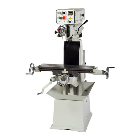
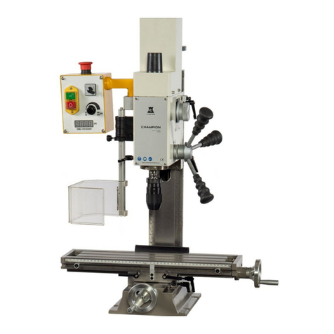
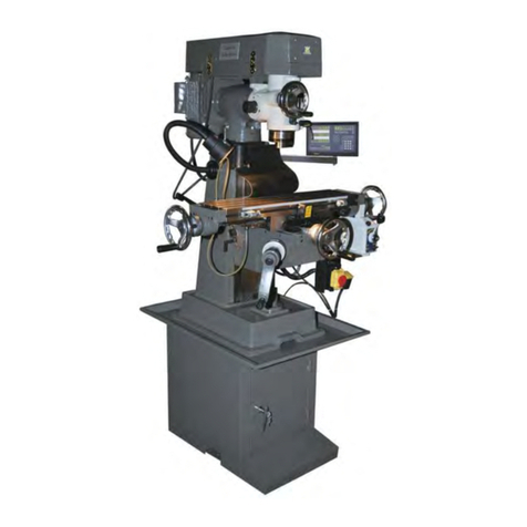
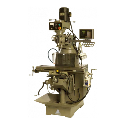
CHESTER T Mill User manual

Contents
1. Warnings
2. Usage
3. Use and Maintenance
4. Main Parameters
5. Transmission System and Change of Speed
6. Machine Lubrications and Roller Bearings
7. Electrical System
8. Transport and Attentions
9. Troubleshooting
10. Parts List and Diagrams

1. Warnings
1. Make sure that the operators read and understand the entire operation manual
before starting to use this machine.
2. Always wear approved safety glasses/face shields whilst using this machine.
3. Before starting the machine, make sure that it has been properly grounded.
4. Do not wear ties, rings, watches or other jewellery and roll up sleeves above the
elbow. Remove all loose clothing and tie back long hair. Do no wear gloves whilst
operating this machine.
5. Keep the floor around the machine clean and free from scrap material, oil and
grease.
6. Keep all of the machine guards in place at all times when the machine is in use, if
they need to be removed for maintenance purposes, use extreme caution and
replace the guards immediately after maintenance has been completed.
7. Do not over reach, maintain a balanced stance at all times so that you do not fall
or lean against cutting tools or other moving parts.
8. Only ever make adjustments or carry out any maintenance after the machine has
disconnected from the power supply.
9. Use the right tool for the task at hand, so not force a tool or attachment to do a job
which it was not designed for.
10.Make sure that the motor switches are in the off position before connecting the
machine to the power supply.
11.Keep visitors a safe distance from the work area.
12.Never attempt any operation or adjustment if the procedure is not known or
understood.
13.Keep hands and fingers away from all of the rotating parts and cutting tools whilst
the machine is in use.
14.Do not attempt to adjust or remove tools during operation.
15.Always keep cutting tools sharp.
16.Keep away from the turning handwheel, especially when operating at high speeds.
17.Only ever pour the correct amount of machine oil into the gearbox and the power
feed, do not over fill.
18.Failure to comply with these warnings may cause serious injury.
Attention
Please carefully check the machine when opening the package and make sure that
no parts are missing.
Please read the operation manual carefully before installing or adjusting the machine.
When the installation is complete, check all of the handles, switches etc. and carry out
a trial run of the machine before putting it into operation.
Be aware of the safety measures for the electrical system and the operation
procedure.
Work Environment
1. The elevation of the workshop should be below 2000m.
2. Do not operate this machine in areas prone to conductive dust.
3. Do not install this machine close to explosive materials.

4. Keep the work area free from corrosive gas or steam which may corrode the metal
or damage the insulation.
5. Keep this machine away from large sources of impact or vibration.
Operating Instructions
1. Before starting the machine, carefully read the operation manual and be fully
acquainted with the features and functions of this machine.
2. The operator should be familiar with all of the safety rules and points for attention
for running and maintaining this machine.
3. Remove all of the anti-rust oil or grease from the machine, fill the machine with
lubricant and cover the bare metal surfaces with a thin layer of machine oil to
protect from rust. Run the machine from low to high speeds and check that the
function is normal.
4. Check that the grounding is reliable and has been properly connected before
operating this machine.
Lubrication
Lubricate the sliding and rotating parts before the trial run.
Pour No.40 machine oil into the gearbox and power feed until the level of oil reached
the line in the oil sight glass before completing an overall check on the machine.
Lubrication Diagram

2. Usage
This machine is used for cutting metals and non-metals. It is suitable for drilling,
boring, milling and is used for instrument making, machining and repairing on single
parts or batch production.
3. Use and Maintenance
Fig 1
1. The user must read this operation manual carefully, they must know the structure
and function of every handle and switch, the transmission system and the
lubrication requirements well.
2. Before operating the machine, inspect the normal conditions of the column locking
handle, the spindle sleeve and the electrical components. Make sure that the
machine has been correctly grounded.
3. When the position of the spindle box to the table needs to be adjusted, two
clamping levers (1) on the right side of the knee must be loosened, the table can
then be raised by using the knee handle. Lock the table in position once the table
is at the required height.
4. This machine has been fitted with a micro feed function, to use this function, turn
the locking bolt (3) located on the right side of the head to engage the micro feed
gear. Use the handwheel (4) located on the front of the head to micro feed the
spindle. The spindle can reverse for tapping using the switch equipped on the left
side of the head (this function is only available on the 3 phase model).
5. The spindle feed lever (5) must be disengaged from the micro feed gear during
drilling and tapping. When the drilling and tapping job is finished, release the
spindle feed lever to allow the lever to reset automatically. The elastic force can
be adjusted after the loosening the screw located in the bottom of the spindle box,
the spring can be turned to a new position. When milling, the spindle sleeve

clamping lever (6) should be tightened to lock the spindle. To obtain the best
machining finish, choose the correct cutting tool and bring the table with the
workpiece up to meet the cutting tool.
6. The boring function of this machine can be realized after the correct tools have
been equipped. For ease of use and for the best results, we recommend using the
micro feed function.
7. The spindle box can be turned ±90° in the vertical plane. When turning the spindle
box, loosen the three nuts connecting the spindle box to the ram and turn the
spindle by using the micro worm (8) before retightening into position. The head
can also be turned ±45° in the vertical plane.
8. The spindle box can also be moved forwards and backwards by moving the ram.
Loosen the two clamping bolts (9) located on the right side of the ram and turn the
gear shaft (10) to move the ram and spindle box. Tighten the clamping bolts when
they are in position.
9. The spindle box can be turned 360° around the column in the horizontal plane.
Loosen the 4 clamping nuts (11) under the ram, the ram can then be turned into
the correct position before re-tightening the 4 clamping nuts.
10.The spindle canbe started by using the switch located on the right side of the knee.
11.The horizontal milling spindle can be realized by turning the vertical spindle box
90°. To use the tool shaft and jack supplied, the spindle box will need to be turned
180°.
12.If the machine does not operate correctly or creates an irregular noise, turn the
machine off immediately and do not restart until the malfunction has been resolved.

4. Main Parameters
Drilling Capacity
25mm
End Mill Capacity
25mm
Face Mill Capacity
100mm
Table Size
240 x 1000mm
Cross Travel
230mm
Vertical Travel
600mm
Longitudinal Travel
780mm
Spindle Taper
ISO30
Spindle Stroke
130mm
T-slot Size
14mm
Spindle Speeds
38-1350rpm
Headstock Tilt
±90º
Quill Travel
120mm
Horizontal Spindle Taper
ISO30
Number of Speeds
Variable 2 Speeds
Cross Feed Rate
Manual
Vertical Feed Rate
Manual
Rapid Cross Feed Rate
Manual
Vertical Cross Feed Rate
Manual
Motor
1.5kW (2hp)
Overall Dimensions
2200 x 1250 x 1450mm
Net Weight
850Kg

5. Transmission System and Change of Speed
1. The transmission of power from the motor to the spindle is provided through two v-
belts.
2. Power is transmitted through the gears on the motor and sliding gears on the
spindle, when changing the speed, stop the machine and move the position of the
handles. Fine adjustment of the speed is then available by using the potentiometer
on the side of the vertical head.
6. Lubrication and Roller Bearings
1. Each roller bearing to be lubricated is shown in the table below,the bearings should
be lubricated with #2 grease.
2. The spindle,sleeve, column and table etc. should be lubricated as per Fig 1. At the
correct intervals.
Position
No.
Location
Bearing
Model
Qty
1
Spindle and Belt Pulley
Single Dust Defence
Radial Ball Bearing
60109/p6
2
2
Spindle Sleeve
Single Dust Defence
Radial Ball Bearing
60109/p6
1
3
Spindle Sleeve
Single Tapered Roller
Bearing
2007110/p6
1
4
Middle Wheel
Single Dust Defence
Radial Ball Bearing
60103
4
5
Spindle
Single Tapered Roller
Bearing
2007111/p6
1
6
Spindle
Single Tapered Roller
Bearing
7308E/p6
1
7
Wheel Shaft
Single Dust Defence
Radial Ball Bearing
60105
2
8
I, II, III
Single Dust Defence
Radial Ball Bearing
60204/p6
6

Fig 2 Roller Bearing Position
7. Electrical System
The electrical control system has been installed on the left side of the machine head,
the electrical system of the horizontal spindle has been equipped under the right front.
The electrical system supplied has been specked to make machining easy and safe
to operate.
8. Transport
When transporting the machine, it must be moved and positioned carefully. Do not
knock the machine when lifting or lowering.
9. Troubleshooting
1. If the motor does not run, inspect the connection to the machine or check the power
source.
2. If the radial run out of the spindle is too large and is noisy and producing excessive
heat, check to see if the spindle is loose. If the spindle is loose, adjust the nut on
the spindle assembly.
3. If the machine wobbles, check the motor mounts, the levers, nuts, screws and the
machine head support on the spindle, if these are loose adjust and lock into
position.
4. If the spindle does not lower or raise easily, inspect the machine to see if there is

any scrap material between the spindle sleeve and gear shaft or fatigue in the
spindle. Clean these parts and apply oil and readjust the spring.
5. If the knee does not lift steadily or it is noisy, check the gib strips, if they are loose,
clean and adjust the gib to the correct position.
6. If the gearbox is noisy, stop the machine immediately and check the condition of
the oil.
7. Make sure that the machine is removed from the power supply before carrying out
any maintenance.
Notice:
The spindle box can be swiveled to ±45°, when operating, please loosen the three
retaining nuts and pay attention, these nuts only need to be released by 1 pitch, the
swivel screw lever can then be moved with a socket wrench to incline the spindle box
to the required angle. Turning the nut clockwise will turn the head counter-clockwise
and vice versa. When turning the head, pay attention to the following:
1. When turning the head from the horizontal to vertical positions, you can help the
movement by pushing the upper spindle box and twist the head.
2. When turning the spindle box from the vertical to horizontal positions, you can help
by pushing on the upper spindle box to twist the head.

10. Parts List and Diagram
Column Parts

No.
Name
Qty
A1
Base
1
2
Column
1
3
Elevating Screw Housing
1
4
Screw
4
5
Washer
4
6
Connect Tube
1
7
Screw
2
8
Bolt
6
9
Washer
6
10
Collar
1
11
Screw
4
12
Hold Support
1
13
Screw
6
14
Around Bracket
1
15
Feed Shaft
1
16
Collar
1
17
Clamp Bolt
2
18
Clamp Block
2
19
Bevel Iron
1
20
Screw
1
21
Overarm
1
22
Cover
1
23
Screw
4
24
Cover
1
25
Screw
4
26
Hold Bracket
1
27
Gear
1
28
Screw
4
29
Bolt
2
30
Nozzle
1
31
Oil Cup
2
32
Screw
2
33
Bolt
1
34
Connect Tube
1
35
Hold Bracket
1
36
Nut
4
37
Washer
4
38
T-Bolt
4
39
Bolt
4
40
Electric Pump
1
41
Bolt
4
42
Support
1
43
Dust Cover
1
44
Screw
2
45
Bevel Iron
1

46
Adjust Screw
1
47
Screw
2
48
Wiper Plate
1
49
Wiper Plate
1
50
Wiper Plate
2
51
Knee
1
52
Clamp Block
2
53
Clamp Bolt
2
54
Vertical Leadscrew
1
55
Circular Nut
2
56
Conical Gear
1
57
Key
1
58
Ball Bearing
1
59
Adjust Washer
1
60
Collar
1
61
Ball Bearing
1
62
Nut
1

Head

No.
Name
Qty
C1
Spindle Box
1
2
Motor base
1
3
Left Cover
1
4
Right Cover
1
5
Pulley Cover
1
6
Screw
4
7
Screw
4
8
Bolt
6
9
Washer
6
10
Cover
1
11
Screw
4
12
Bolt
2
13
Washer
1
14
Cover
1
15
Screw
1
16
Bolt
2
17
Washer
1
18
Motor
1
19
Headless seat screw
1
20
Worm Gear
1
21
Pin
1
22
T-Bolt
3
23
Nut
1
24
Feed Shaft
1
25
Key
1
26
Worm Box
1
27
Screw
3
28
Bevel Gear
1
29
Retaining Ring
1
30
Spring
1
31
Scale Ring
1
32
Handle Bracket
1
33
Cover
1
34
Bolt
1
35
Handle Bar
3
36
Knob
3
37
Handle
1
38
Handle Collar
1
39
Scale
1
40
Rivet
2
41
Worm Gear
1
42
Ball Bearing
1
43
Small Cover
1
44
Screw
3
45
Ball Bearing
1

46
Collar
1
47
Scale Ring
1
48
Handwheel
1
49
Handle Collar
1
50
Handle
1
51
Nut
1
52
Key
1
53
Clamp Block
1
54
Clamp Block
1
55
Clamp Handle
1
56
Screw
1
57
Spring Seat
1
58
Screw
1
59
Screw
1
60
Spring Plate
1
61
Spring cap
1
62
Screw
2
63
V Belt
1
64
Nut
1
65
Spindle Pulley
1
66
Spring Sleeve
1
67
Collar
1
68
Screw
3
69
Retaining Ring
3
70
Ball Bearing
1
71
Collar
1
72
Ball Bearing
1
73
Retaining Ring
1
74
Retaining Ring
1
75
Pulley Nut
1
76
Washer
1
77
Ball Bearing
1
78
Sleeve
1
79
Ball Bearing
1
80
Dust Cover
1
81
Spindle
1
82
Spindle Bar
1
83
Drill Chuck
1
84
Wedge Shifter
1

Horizontal Spindle

No.
Name
Qty
D1
Screw
4
2
Key
2
3
Screw
4
4
Oil Cup
1
5
Cover
1
6
Spindle
1
7
Ball bearing
1
8
Collar
1
9
Ball bearing
1
10
Washer
1
11
Washer
1
12
Nut
1
13
Cover
1
14
Screw
4
15
Oil Cup
1
16
Spindle Pulley
2
17
Key
1
18
Retaining Ring
1
19
V Belt
2
20
Key
1
21
Retaining Ring
1
22
Wheel
1
23
Ball bearing
1
24
Ball bearing
1
25
Ball bearing
1
26
Collar
1
27
Ball bearing
1
28
Small Shaft
1
29
Collar
1
30
Support
1
31
Screw
2
32
Bolt
1
33
Nut
1
34
Retaining Ring
1
35
Retaining Ring
1
36
Nut
2
37
Retaining Ring
1
38
Pulley
1
39
Retaining Ring
1
40
Key
1
41
Motor base
1
42
Screw
6
43
Nut
1
44
Washer
1
45
Washer
1

46
Small Shaft
1
47
Connect
1
48
Retaining Ring
1
49
Ball bearing
1
50
Collar
1
51
Ball bearing
1
52
Retaining Ring
1
53
Retaining Ring
1
54
Pulley
1
55
V Belt
1
56
Adjust Screw
1
57
Support
1
58
Screw
1
59
Nut
1
60
Motor
1
61
Washer
4
62
Bolt
4
63
Motor Wheel
1
64
Screw
1
65
Key
1
66
V Belt
1

Gearbox
Table of contents
Other CHESTER Power Tools manuals
Popular Power Tools manuals by other brands

Bosch
Bosch Professional GOP 18V-34 Original instructions

Matco Tools
Matco Tools DT4B operating instructions

Würth
Würth 1952 003 133 Translation of the original operating instructions

Singer
Singer Intelligent Pro Steam Press instruction manual
abc
abc K 3782/4 instructions
Cleco
Cleco 400PTHFC206 instruction manual

