CHESTER Conquest Super Mill User manual


Contents
1. Specification
1.1 Machine Specification
2. Machine Installation
2.1 Fundamental Location of the Machine
2.2 Preparation before Operation
3. Prevention and Maintenance
3.1 Prevention and Maintenance
3.2 Maintenance of the Cutter and Taper Shank
3.3 Mechanics Lubrication
4. Machine Structure
4.1 External Features
4.2 Assembly and Parts
5. Mechanism Adjustment
5.1 Installation and Removal of the Taper Shank
5.2 Travel Adjustment
5.3 Adjust Tip Angle of Head
6. Operation and Notices for Use
6.1 Method of Operation
6.2 Operation Safety Notes
7. General Safety Instructions
8. Power Connections and Electrical Drawings
8.1 Power Connection/Disconnection & Operation
8.2 Electrical Circuit Diagram
2

Some Safety Features of this Machine
Purpose of this Machine:
This machine has been designed for drilling, deep milling and face milling of small workpieces
with a size limitof 300mm x 200mm x 200mm. If the operator intends to use this machine beyond
its design, please contact the manufacturer or dealer before starting the operation
The Following Should be Obeyed before Operating
Do not operate this machine before reading this manual thoroughly.
Do not use this machine without professional training of drilling and milling operations.
Do not operate this machine outside of its design parameters without first consulting the
manufacturer or dealer.
When operating this machine, make sure that every safety precaution is followed as indicated in
this manual.
Some Important Safety Information
The noise level during the operation of this machine is between 70-75dB(A).
The temperature range suitable for the operation and storage of this machine is between -20°C
to +40°C.
Special Warnings for this Machine
Warning! There is a risk of the machine accidentally restarting after a power failure, make sure
that all of the operation switches are in the off or neutral positions if the power is interrupted.
Warning! Always wear approved eye protection when operating this machine.
Correct Handling of this Machine
The net weight of this machine is approximately 58Kg, we recommend using the correct lifting
equipment when moving this machine.
If the operator has to handle the machine without lifting apparatus, make sure that you can
comfortably lift this weight. Handle the machine with care and be aware of your surroundings to
prevent accidents.
3

1. Specifications
This is a mini vertical milling machine with multiple functions to be able to either face mill or drill
etc. As such there are various sizes and types of cutting tools available for this machine that are
easy to purchase, these can ensure that you work more accurately and efficiently as you change
the cutter upon your work demands.
1.1 Machine Specifications
Max Table Travel 300mm (12”)
Max Cross Slide 100mm (5”)
Max Spindle Travel 180mm (7”)
Spindle Angle Rotation ±45°
Spindle Speed 100-2500rpm
Taper Hole in Spindle MT3
Drilling Capacity 13mm
End Mill Capacity 16mm
Face Milling Capacity 30mm
Machine Weight 50 -58kg
T-Slot Specification
4

2. Machine Installation
2.1 Fundamental Location of the Machine
This machine should be fixed on to the worktable with four hexagon bolts. Please install the
machine in a suitable location in order to ensure the precision if the machine.
Selecting a Suitable Location for Installing the Machine
1. The worktable should be flat.
2. Avoid locations in direct sunlight, damp or dusty conditions, these will all have an effect on the
machine’s accuracy and life span.
Method of Installation
1. Drill 4 holes on the worktable the same size asthe holes in the
machine base. Note: consider the position of the Y axis
handwheel when selecting the machines’ location.
2. Adjust the machines level and secure the machine to the
worktable with 4 M10 Bolts and Nuts.
2.2 Preparation Before Installation
1. Remove all the fixing equipment and clean around the machine once located in place.
2. Ensure that the supplied voltage is suitable for the machine.
3. Remove any obstacles from around the machine.
4. Clean all the anti-rust protection off from the machine.
5. Check the angle of the pillar and adjust the bolts (tighten if loose).
6. Check the chuck, chuck holder and fixing pin on the spindle to ensure that they are not loaded.
7. Check the high-low speed on the spindle, to ensure it sets on the right speed.
8. Turn on the machine and check the spindle is rotating clockwise.
9. Operate the longitudinal axis (working table), cross axis (saddle seat) and the vertical axis
(fuselage) to check the workings are correct.
10. Whilst operating, be careful to watch the machine when manipulating your work. If the
machine starts to behave abnormally, stop operating and investigate.
5

3. Prevention and Maintenance
3.1 Prevention and Maintenance
Daily Maintenance
1. Inspect each operating part to ensure lubrication.
2. Examine the machine to ensure all the parts are fixed securely.
3. Clean and remove any obstacles around the machine, in order to ensure safety and prevent
damage.
4. After daily use lubricate all the moving parts in order to prevent rust and damage.
5. Whilst operating, be careful to watch the machine when manipulating your work. If the
machine starts to behave abnormally, stop operating and investigate.
Monthly Maintenance
1. Use clean cotton wool or soft gauze to clean the machine.
2. Check the motion of the head of the machine to check whether it is smooth or loose.
3. Check the over swing in the spindle.
4. Check all the bolts and nuts for looseness.
5. Examine the overall circuit (contact points, conductor plugs and switches...etc) for faults.
Yearly Maintenance
1. After maintenance, make a record.
2. Before replacing any faulty parts, stop the machine.
3. Maintenance and repair should be done on a regular basis. If the machine starts to operate
unusually, stop and investigate.
4. If the fault on the machine is beyond your own ability to repair, contact Chester UK or a local
service engineer.
3.2 Maintenance of the Cutter and Taper Shank
1. When not in use keep the cutter packed away, in order to maintain the sharpness and quality
of the blade.
2. Check the rotation of the cutter, rotation in the wrong direction might split the blade and
accelerate the cutter to exhaustion. If you have difficulty in identifying the blade direction, whilst
in high speed mill the working piece.
3. Sharpen the cutter after use, a dull blade makes milling allot harder to accomplish.
4. Keep the taper shank and cutter clean.
5. The draw bar and chuck have their own wrenches. Keep the wrenches near the machine and
never operate with inappropriate tools.
6

3.3 Mechanics Lubrication
In order to ensure the precision of the machine it would be well advised to lubricate all the
moving parts.
The following parts on the machine need the following applied to ensure lubrication:
After you have finished your work, clean the worktable and lubricate accordingly.
7
USE LUBRICATING OIL
USE LUBRICATING GREASE
1. Basement and saddle seat slide face.
1. X-Axis feeding screw (saddle seat).
2. Saddle seat and working table slide face.
2. Y-Axis feeding screw (working table).
3. Fuselage sear and connecting strut slide face.
3. Z-Axis feeding gear rack (fuselage).
4. Fuselage and spindle box slide face.

4. Machine Structure
4.1 External Feature:
8
A. Motor
B. Headstock housing & spindle
C. Chuck
D. Longitudinal feed handle wheel
E. Working table
F. Saddle
G. Cross feed hand wheel
H. Base
I. Connecting strut
J. Controller
K. Fuselage
L. Limit block
M. Cushioning cylinder
N. Fine feeding wheel
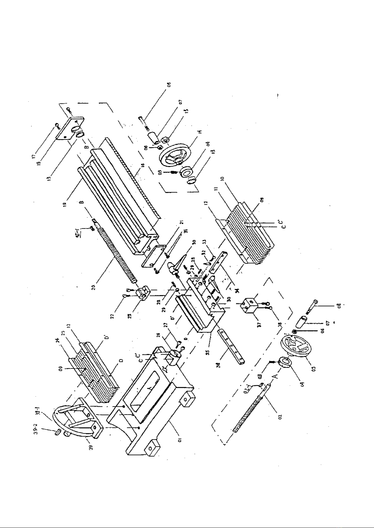
4.2 Assembly and Parts
LONGITUDINAL (Y) AXIS, CROSS (X) AXIS
9
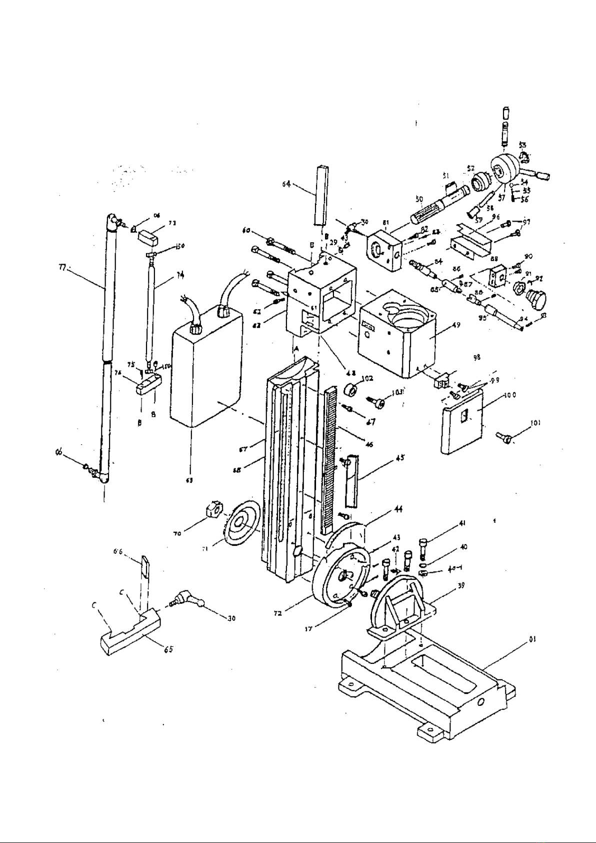
VERTICAL (Z) AXIS
10
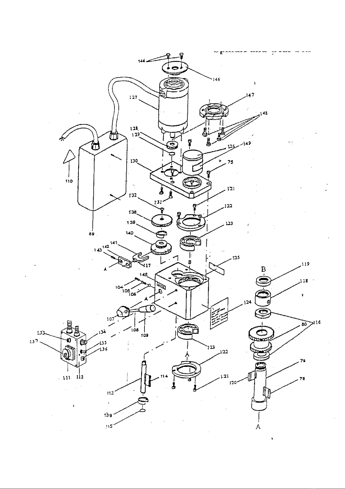
SPINDLE & GEAR BOX
11

PARTS LIST
ITEM No.
DECRIPTION
Q'TY
ITEM No.
DECRIPTION
Q'TY
241-S-1
Base
1
241-S-38
Cap screw M6 X 25
2
241-S-2
X-axis feeding screw
1
241-S-39
Fuselage seat
1
241-S-2-1
Key 4 X 16
2
241-S-39-1
Shaft
1
241-S-3
Spring
2
241-S-39-2
Key 8 X 12
1
241-S-4
Graduated collar
2
241-S-40-1
Washer 10
3
241-S-5
Hand wheel
1
241-S-41
Cap screw M10 X 30
3
241-S-6
Nut M8
4
241-S-42
Guide finger
2
241-S-7
Knob
2
241-S-43
Set screw M6 X 16
7
241-S-8
Screw M8 X 55
2
241-S-44
Ruler
1
241-S-9
Cap screw M6 X 8
8
241-S-45
Wedge
1
241-S-10
Holding plate 1
1
241-S-46
Gear rack
1
241-S-11
Dust guard cover
1
241-S-47
Cap screw M6 X 16
4
241-S-12
Holding plate 2
2
241-S-48
Name plate
1
241-S-13
Ball bearing 8200
2
241-S-49
Spindle box
1
241-S-14
Hand wheel
1
241-S-50
Pinion
1
241-S-15
Nut M8
8
241-S-51
Key 4 X 25
1
241-S-16
Y-axis ruler
1
241-S-52
Bevel gear
1
241-S-17
Cap screw M6 X 16
6
241-S-53
Retaining ring 12
1
241-S-18
Y-axis bearing seat
1
241-S-54
Ball Ǿ 5.0
1
241-S-19
Working table
1
241-S-55
Spring 0.8 X 0.8 X 10
1
241-S-20
Y-axis feeding screw
1
241-S-56
Screw M6 X 8
1
241-S-21
End cover
1
241-S-57
Handle stock
1
241-S-22
Cap screw M6 X 10
2
241-S-58
Operating lever
3
241-S-23
Y-axis screw nut
1
241-S-59
Lever cap
3
241-S-24
Holding plate 3
1
241-S-60
Cap screw M8 X 25
4
241-S-25
Dust guard cover
1
241-S-61
Guide finger
1
241-S-26
Screw seat
1
241-S-62
Cap screw M6 X 25
1
241-S-27
Cap screw M6 X 16
2
241-S-63
Spindle box seat
1
241-S-28
Set screw M6 X 22
6
241-S-64
Wedge
1
241-S-29
Nut M6
13
241-S-65
Limit block
1
241-S-30
Handle
3
241-S-66
Wedge
1
241-S-31
Screw M6 X 10
2
241-S-67
Ruler
1
241-S-32
Guide finger
1
241-S-68
Fuselage
1
241-S-33
Screw M6 X 8
1
241-S-69
Electric box
1
241-S-34
X-axis wedge
1
241-S-70
Lock nut M24
1
241-S-35
Saddle
1
241-S-71
Big washer
1
241-S-36
Y-axis wedge
1
241-S-72
Connecting strut
1
241-S-37
X-axis screw nut
1
241-S-73
Connecting board
1
12

ITEM No.
DECRIPTION
Q'TY
ITEM No.
DECRIPTION
Q'TY
241-S-74
Pitman shaft
1
241-S-114
Double round head key 4 X 4 X 45
1
241-S-75
Cap screw M6 X 20
2
241-S-115
Internal ring Ǿ 12
1
241-S-76
Connecting block
1
241-S-116
Spacing ring
2
241-S-77
Cushioning cylinder
1
241-S-117
Small shaft
2
241-S-78
Key 5 X 5 X 40
1
241-S-118
Spacing ring
1
241-S-79
Spindle
1
241-S-119
Spindle nut
1
241-S-80
Transmission gear
1
241-S-120
Double round head key 5 X 5 X 30
1
241-S-81
Support block
1
241-S-121
Cap screw M5 X 8
1
241-S-82
Screw M5 X 20
2
241-S-122
Bearing cover
6
241-S-83
Pin 4 X 15
1
241-S-123
Ball bearing 6206ZZ
2
241-S-84
Worm
1
241-S-124
Name plate
2
241-S-85
Sleeve
1
241-S-125
Fine feeding label
1
241-S-86
Pin 3 X 12
1
241-S-126
Protecting cover
1
241-S-87
Pin 3 X 12
2
241-S-127
Motor
1
241-S-88
Adjustable union
1
241-S-128
Motor gear
1
241-S-89
Bracket
1
241-S-129
Intering ring 9.0
1
241-S-90
Screw M5 X 25
1
241-S-130
Motor seat
1
241-S-91
Dial
1
241-S-131
Flat screw M5 X 8
1
241-S-92
Spring steel 1.0
1
241-S-132
Round screw M5 X 8
1
241-S-93
Small hand wheel
1
241-S-133
Lamp
1
241-S-94
Screw M4 X 14
1
241-S-134
Speed control knob
1
241-S-95
Small shaft
1
241-S-135
Switch
1
241-S-96
Cover
1
241-S-136
Fuse box
1
241-S-97
Screw M4 X 6
2
241-S-137
Emergency stop switch
1
241-S-98
Support of dust cover
1
241-S-138
Gear
1
241-S-99
Screw M5 X 16
2
241-S-139
Ball bearing 80101
2
241-S-100
Dust guard
1
241-S-140
Transmission gear
1
241-S-101
Clamp bolt M6 X 12
1
241-S-141
Bar
1
241-S-102
Upper end washer
1
241-S-142
Linking board
1
241-S-103
Upper end screw M6 X 16
1
241-S-143
Set screw M5 X 8
1
241-S-104
Set screw M6 X 6
1
241-S-144
Self-tapping screw ST 2.9 X 8
2
241-S-105
Spring 0.8 X 4.8 X 10
1
241-S-145
H / L label
1
241-S-106
Ball Ǿ 5.0
1
241-S-146
Motor cover
1
241-S-107
Handle seat
1
241-S-147
Motor connecting flange
4
241-S-108
Double head bolt M8 X 70
1
241-S-148
Screw M6 X 10
1
241-S-109
Knob
1
241-S-149
Warning label
1
241-S-110
Warning label
1
PC board
1
241-S-111
Controller
1
Potentiometer
1
241-S-112
Label on controller
1
Fuse
1
241-S-113
Shaft 1
1
241-S-150
Nut M10
2
13

5. Mechanism Adjustment
5.1 Installation and Removal of the Taper Shank
Installation
1. Turn off the main power source before you replace the cutter.
2. Pull out the protective cover (a).
3. Wipe the spindle sleeve and taper shank.
4. Put the taper shank (g) into the spindle sleeve. The cutter should be matted with an oil cloth.
5. Insert the fixing pin (d) on the spindle sleeve.
6. Use #14 open end wrench (c) to tight (clockwise) spindle draw bar (b) for fixing the taper
shank.
7. Pull out the fixing pin.
8. Install the protective cover (a).
Removal
1. Turn off the main power before you replace the cutter.
2. Pull out the protective cover (a).
3. Insert the fixing pin (d) right on spindle sleeve.
4. Use the #14 open end wrench (c) to loosen.
5. Knock the taper shank (g) gently.
6. Cutter should be matted with an oil cloth.
7. Install the protective cover (a).
14

5.2 Travel Adjustment
Using the limit block can control the travelling of the spindle box.
1. Loosen the handle (a) at the side of the limit block.
2. Adjust the limit block (b) in position.
3. Tighten the handle.
4. Travel position can refer to the ruler on the fuselage rotary.
5.3 Adjust Tip Angle of Head
1. Disconnect the machine from the main power source before you make any adjusts to the
machine.
2. Secure the machine.
3. Loosen the locked nut (a) with a wrench (b).
4. Adjust the fuselage dip angle to your required angle (Max is 45˚, in either direction).
5. Tighten the nut after adjustments have been made.
15

6. Operation and Notices for Use
6.1 Method of Operation
Drilling or Deep Milling
1. Referring to pages 15 & 16, replacement of the chuck and tool. Adjust appropriately and
tighten.
2. Select a speed at which to operate the machine. (NB: When engaging the spindle don’t
change the high / low speed!)
3. Use the press cake or fixture to set the workpiece on the worktable.
4. Adjust the worktable (Longitudinal Axis (Y)) and the saddle seat (Cross Axis (X)) in position.
5. Loosen the limit block handle, adjust the blocks in position. Note: Don’t let the tool meet the
workpiece.
6. Put the adjusting tools in order and proceed to clear the work area.
7. Turn on the main power, and then adjust to an appropriate spindle speed for drilling or deep
milling.
8. Refer to the ruler on the fuselage to confirm drilling or milling depth.
9. When you have finished your work on the machine return the spindle to the upper position.
10. Clean the machine.
Face Milling
1. Referring to pages 14 & 15 concerning the replacement of chuck + tool. Adjust appropriately
and tighten.
2. Select the appropriate speed. (NB: When engaging the spindle don’t change the high /
low speed!)
3. Use the press cake or fixture, to set the workpiece on the working table.
4. Adjust the working table (Longitudinal Axis (Y)) and saddle seat (Cross Axis (X)) in position.
5. Release the limit block on the fuselage, adjust the depth of cut and then fix.
6. Put your work tools away.
7. Turn the hand wheel of the working table (Y-axis), and then adjust the saddle seat (X-axis) to
engage face milling.
8. When you have completed your work, turn off the power and return the spindle to the upper
position.
9. Clean the machine.
Drilling or Milling Speed
Before any operation, set the spindle to a correct running speed. The operating speed range for
working is 0 to 2500rpm.
To find the correct speed of running you will have to consider the size of the working face and
which material you are working with. Generally, you can use higher speeds for softer materials
or small holes, and vice versa for harder materials.
Refrain from operating above 2300rpm, when working with wood. For metal you can operate the
machine from 0 to 2500rpm.
16

6.2 Operation Safety Notes
Notice Before Operating the Machine
Before operating, check off the following to ensure a safe operation of the machine.
Inspection Before Operation
1. Before you turn on the power, check the tool chuck is in the correct position and tighten.
2. Inspect the machine for parts that are not secure.
3. Adjust the speed to the required setting and then check it against the chart to see if correct.
4. Fix the workpiece with the press cake or fixture.
5. Clean and then remove all the obstacles around the machine.
During Operation
1. Consuming alcohol, drugs or operating the machine whilst on strong medicines is not
recommended.
2. The wearing of loose clothing whilst working on the machine is not recommended.
3. Attach the appropriate cutter and tighten.
4. The Chester Conquest Mill will not operate safely if you attempt the following:
a. The depth of the cut is too deep.
b. The feeding speed is too fast.
c. The rotation speed is too fast.
d. The machine and stock plane are not firmly fixed.
e. The vice and the workpiece are not firmly fixed.
Protection and Maintenance
1. Disconnect the machine from the power source.
2. Maintain the machine and make a record of the work carried out.
3. Inform Chester UK on: 01244 531631 should the machine start to malfunction.
17

7. General Safety Instructions
Warning! When using electric tools basic safety precautions should always be adhered to. This
will help to reduce accidents whilst working on the machine. Below is a brief guide:
1. Keep your area clean.
- Cluttered areas increase the risk of an accident.
2. Review your area of work.
- Don’t expose the machine or parts to rain.
3. Keep the area of work well lit.
- A poorly lit workplace increases the risk of an accident happening.
4. Guard against electric shock.
-Avoid body contact with an earthed or grounded surface (e.g. pipes, radiators, ranges,
refrigerators...etc)
5. Keep children away from the machine.
-Children can possibly harm themselves on heavy machinery, so it would be best to keep
them away from any possible danger that may occur.
6. Store idle tools.
-When not in use your tools should be stored in a out of the way storage area, that is kept dry.
7. Use the right tools.
-You will accomplish your job at a better and safer rate.
8. Don’t force the tools.
- It will do the job better and safer at the rate for which it was intended.
9. Dress properly.
- Don’t wear loose clothing or jewellery, as they can be caught in moving parts. Rubber gloves
and non-skid footwear are recommended when working outdoors. Wear protective hair covering
to contain long hair.
10. Use safety glasses.
- It would be wise to also use a facemask, if the work being done is dusty.
11. Connect dust extraction equipment.
- If devices are provided for the connection of extraction and collection equipment, ensure that
they are properly connected and used.
12. Do not abuse the cord.
- Never carry a tool by the cord or yank the cord, as it will disconnect it from the socket. Keep
the cord away from heat, oil and sharp edges.
13. Secure work.
- Use a clamp or a vice to hold the work. You can then start using your hands.
18

14. Do not overreach.
-Try to keep a proper footing and balance at all times.
15. Maintain the tools with care.
- Keep the cutting tool sharp and clean for a better / safer performance. Follow the instructions
for lubricating and changing accessories. Inspect the tool cord periodically and replace if
damaged. Try to keep the handle dry & clean, free from oil & grease.
16. Disconnect the tools.
- When not in use, before servicing and when changing accessories, such as the blade, bits &
cutters etc.
17. Remove the adjusting keys and wrenches.
- Form the habit of periodically checking to see that the keys and adjusting wrenches are
removed from the machine before turning it on.
18. Avoid unintentionally starting machine.
- Don’t carry a plugged in tool, whilst your finger is placed on the switch. Check to see if the
machine is switched off, before you plug it in.
19. Using outdoor extension leads.
- When you use your machine outdoors, ensure to check that that the cables are intended for
outdoor use.
20. Check for damaged parts.
- Before any further use of the tool, guard or part of the machine, should be firstly checked to
see if it has sustained any damage. Check the alignment of the moving parts, free running
moving parts, breakage of parts, mounting and any other conditions that may affect its
operation. A guard or other part that has been damaged, should be repaired or replaced
accordingly. Defective switches should only be replaced by Chester UK or a qualified engineer /
electrician. Do not use the machine on/off switch does not function.
21. Stay alert.
- Watch what you are doing. Use common sense. Don’t try to operate the machine when tired.
22. Warning.
- The use of any accessory or attachment, other than those recommended in this instruction
manual, may present a risk to health.
23. Have your tool repaired by a qualified person.
- This electric tool is in accordance with the relevant safety requirements. Repairs should only
be carried out by Chester UK or a qualified engineer / electrician, using original spare parts.
19

8. Power Connections and Electrical Drawings
8.1 Power Connection/Disconnection & Operation
1. The connection, disconnection and grounding, is carried through the plug and equipped on
the machine. For safety reasons, don’t exchange the type of plug for any other.
2. For the protection of the control device, we recommend the operator to supply a fuse with the
current rating and total length between the fuse and the connection terminal shall be according
to the following chart (see below).
Extension Lead Chart
3. The exact power source is 110V or 230V single phase 50 / 60Hz (see label in front of the
machine).
4. Make sure the emergency Stop switch (A) (left beside the electrical box) is in “OFF” position
before plugging in the cord.
5. Disconnect the tools from the power source, before servicing and changing the accessories,
such as the chuck guard etc.
Operation
1. Initial Start
Considering all the relevant precautions stated previously, set the HIGH / LOW range lever to
Low. Connect the machine to a power supply. Engage switch ‘E’ in the ‘I’ position on the motor,
then release the Emergency Stop Switch (‘A’) by pushing down on the red knob slightly and
pushing it up (as indicated by the arrow on the top of the Switch).
Ampere Rating
3A
6A
10A
13A
Extension Cable Length
Wire Size mm2
7.5m
0.75
0.75
1
1.25
1.5m
0.75
0.75
1
1.5
22.5m
0.75
0.75
1
1.5
30m
0.75
0.75
1.25
1.5
45.5m
0.75
1.25
1.5
2.5
Table of contents
Other CHESTER Power Tools manuals


