Chi Lok Bo Toys Lamborghini 615577 User manual
Lamborghini Battery
Operated Ride On
Contents
1. Product Specications
and Parameters
ko1221
615577 EN
Read Operation
Instructions Care-
fully Before Use
1. Product Specications and Parameters
2. Components List
3. Assembly Diagram
4. Installation and replacement of remote control batteries
5. Function and Operation
6. Battery and Charger Operating Guide
7. Simple Fault Removal Guidance
8. Warning
• This product is suitable for
children aged 3-6, and should be
used under adult supervision!
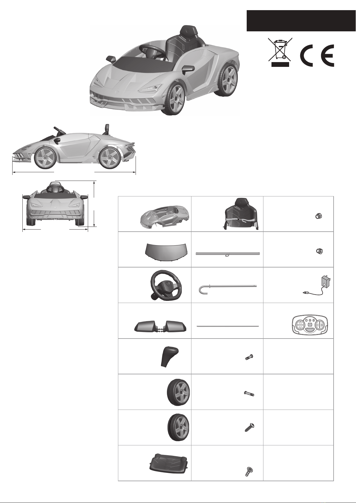
• Product dimensions: 134.7 × 73
× 49 cm
• Product maximum load weight:
30 kg
• Product speed: 2.5 / 3.4 / 4.2
km/h
• Product driving motor: DC
6V/12000r (550 dual drive)
• Product charger: input AC
100-240V (50/60Hz), Output DC
15V/800mA
• Product rechargeable battery:
DC 12V/7AH (1 piece), about 200
cycles of charging and dischar-
ging
• Remote control and manual
switching functions, 2.4 GHz one-
to-one remote control function
• Remote control DC power supp-
ly: 2×1.5V AAA batteries (not
included in this product)
• Product operating ambient tem-
perature: 0-40 °C
• Basic frequency: 2.4-2.4835 GHz
• Transmission power: Iess than
10 dBm
The “Lamborghini” and “Lamborg-
hini Bull and Shield” trademarks,
copyrights, designs and models are
used under license from Automobili
Lamborghini S.p.A, Italy.
134.7CM
49CM
73CM
Dimensions of entire car
2. Components List
3. Steering
wheel
2. Windshield
1. Car Body
7. Driving wheel
(with rubber
wheel sleeve)
2 PCS
10. Front axle frame
connecting-rod
12. Rear wheel axle
11. J-shaped stick
5. Hand shank
8. Seat
9. Seat backrest
4. Rear-view mirror
13. Front axle frame
connecting-rod screw
(5×13 PM)
2 PCS
14. Steering wheel screw
(5×33 PM)
6. Wheel 2 PCS
15. Seat and backrest screw
(4×15 TAB) (D=7.5)
4 PCS
16. Steering gearbox screw
(3×10 PWAB) (D=10)
2 PCS
17. Front axle frame
connecting- rod locknut
(5 mm) 2 PCS
18. Steering wheel
locknut (5 mm)
19. Charger
20. Remote control
10
17
13
7
6
7
6
12
b
b
a
b
c
c
b
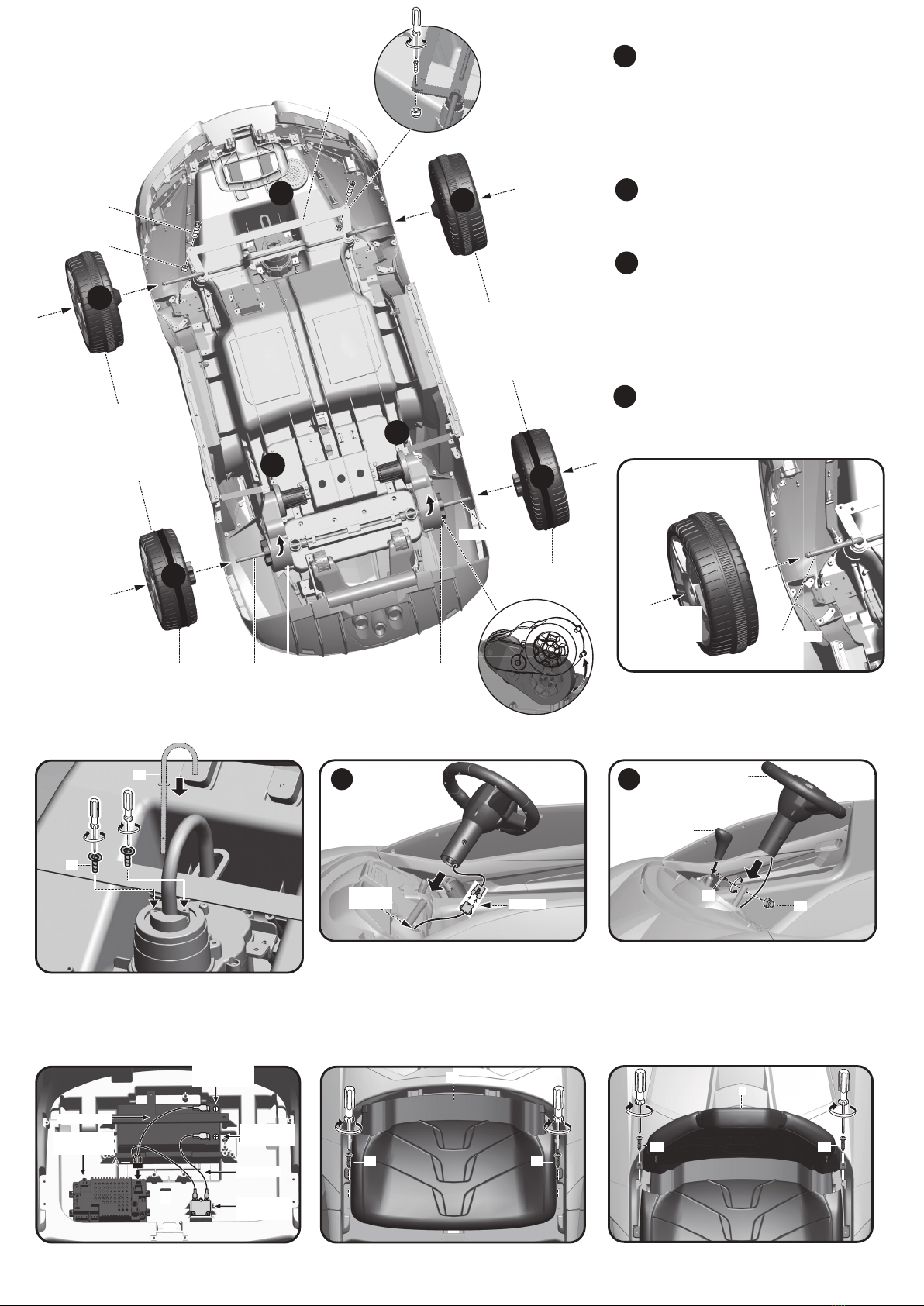
1. Installation of front axle frame connecting-rod
and wheel
2. Installation of J-shaped stick
4. Installation of power supply 5. Mount seat and seat backrest
3. Installation of steering wheel
and hand shank
3. Assembly Diagram Install the front axle frame connect-
ing-rod (part 10) at the assigned
location, and then tighten it with the
front axle frame connecting-rod screw
(part 13) and locknut (part 17) (the
tightening degree shall be based on
the exible swing direction).
Use the thumb to press the wheels’
(part 6) center button, and then put
them into the front axle in sequence.
Rotate the motor gearbox upward
according to the direction indicated
by the arrow until the motor gearbox
hole aligns with the car body axle
hole, and then insert the rear axle
(part 12) into the assigned location of
the car body.
Use the thumb to press the center
button of the driving wheels (part 7)
to put them into the rear wheel axle in
sequence.
a
b
c
d
When the wheels are installed, press the center
button of the wheels, insert the wheels into the
front axle and x them; press the center button
of the wheels to pull out the wheels from the
axle so as to remove the wheels.
Insert the J-shaped iron hook (part 11) into the
front gearbox, and then tighten it by using the
steering gearbox screw (part 16).
Insert plug (A) into the circuit board to its bottom.
Plug the wire plug of the steering wheel into
the wire plug from the car body hole corres-
pondingly, and then put the connected plugs
into the car body hole.
Install the steering wheel (part 3) on the
J-shaped iron hook, and tighten with the
steering wheel screw (part 14) and the
steering wheel anti-loose nut (part 18); then
insert the handle (part 5) into the designated
position and press down rmly to make it
reliably connected.
Gearbox Gearbox
Rear wheel axle
Wheel with rubber
wheel sleeve
Wheel with rubber
wheel sleeve
Press the center
button of the
wheels. Front axle
16
11 21
A
8
8
After installing the power supply, assemble
the seat (part 8) on the specied position
and tighten it with the seat screw (part 15).
Put the seat backrest (part 9) into the assigned loca-
tion of the car body as shown in the gure below, and
tighten it with the seat backrest screw (part 15).
Circuit board
placing box
Overcurrent
protection
Battery red-
plug (+)
Battery
black-plug (-)
Red cable
Black cable
8
15 15
18
14
5
3
Plug-in
Car body
hole
15 15
9
20
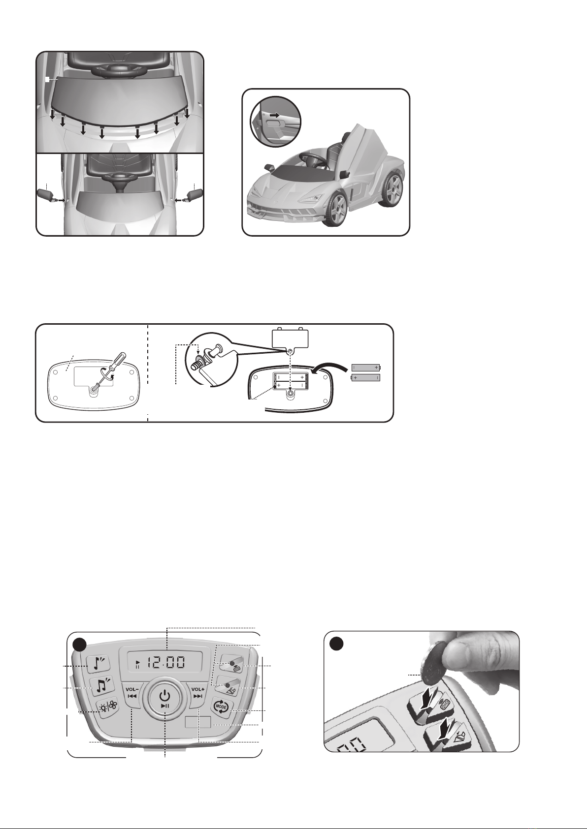
6. Installation of windshield and rear-view mirror
7. Open the car door
Install the windshield (part 2) and rear-view
mirror (part 4) at the assigned location of the
car front end, nd each buckle position before
installation, and then press it forcefully until
each buckle position is tight.
It is o by default at startup. Press it once to turn
on the lamp and the green lamp for this button
is on; press it again to turn o the car lamp and
the green lamp for this button is o.
4. Installation and replacement of remote control batteries
2.4GHz Remote Control
2x1.5V AAA Batteries
The xing glue meson
on the screw can pre-
vent the screw from
dropping out.
Battery
Compartment
Battery Cover
Unscrew the battery cover screws of the
remote control (part 20), open the battery
cover, nd the positive and negative poles,
put 2 AAA batteries into the battery com-
partment, then close the battery cover and
x it with screws.
5. Function and Operation
1. Main functions:
1. Remote control and foot-tread change-over switch
2. Rear drive: Power motor gearbox for powerful front / rear power.
3. Forward / Backward function: The right side of the dashboard is provided with the three forward gears for speed regulation,
neutral gear and reverse gear (each gear has LED lamp display function.)
4. Foot switch function: Press the foot switch button; when the handle is in forward or backward position, step down the foot
switch to move the car forward or backward, and release the foot switch to stop the car.
5. Charging protection function: All functions needing to be powered by the battery will fail when the battery is being charged.
6. Forward / Backward brake function: No matter whether the forward or backward position is operated, there will be the relay
brake function during stop.
7. Turn the auxiliary pull wheel at the bottom of the car out, and turn the pull handle at the front bottom of the car out to pull it
away.
2. Functions on the central control board:
MUSIC V
USB
BT
1
Music
Music
Light/fan
Foot switch
Mode switch
USB interface
Voltage display
Remote
control
One-button start (main switch)
Previous music
volume (-)
(please use a
coin to press
this switch)
Next music
volume (+)
Please use a coin to press the button (remote control
button, pedal button) on the main control panel.
V
USB
BT
2
Please use a
coin to press
this button
2
4 4

Mode switch:
It is by default the built-in music play mode, there is the“music
player” English prompt sound, and the display“MUSIC” will always
be on.
Press this button and switch to USB mode, there is the “USB mode”
English prompt, and“USB”on display will ash (ash when USB
is not connected, and it will always be on when it is connected to
USB);
Press this button again and switch to BT Bluetooth mode, there
is the“bluetooth mode”English prompt, “BT”on display will ash
(ash when Bluetooth is not connected, and it will always be on
when Bluetooth is connected);
Press this button again and switch back to the built-in music play-
back mode.
Loop
It will be
as such
USB
mode
BT
mode
Music
mode
Press Press Press Press
Display function:
Four digits display:
The middle four digits display the voltage of the battery in real
time; it will display the volume change in adjusting the volume
(U00-U30); the song (0001-9999) in USB music will also be displayed
during USB playback.
The function icons on both sides of the display are“MUSIC,USB, BT,
V, , ”, and the mode or state in which it lies will be displayed by
its corresponding icon.
Bluetooth playback function:
In Bluetooth mode, after connecting Bluetooth, the“BT” on display
will always be on, and then the audio le in the
Bluetooth device can be played.
When Bluetooth is disconnected, there is a “dingding”prompt tone,
and“BT”on display will ash.
Name of Bluetooth: CHILOKBO
One-button start button:
Press this button to turn on the main power; the system is in
standby mode, and the trumpet gives a sound of the engine. The
red light of the one-button start button and the green light of the
foot switch mode button will be on, displaying “00.00” with "V", and
the normal voltage will be displayed after the engine sound; the
English prompt sound of "music player" music then plays, and the
music button will be invalid until the prompt sound is over.
After pressing this button for 2 seconds, the main power will be cut
o and the system will be shut down.
Music button:
Under MUSIC play mode, press this button to play a song, and the
green light of this button is on; press this button again to play the
next song; there are 2 music buttons, each button will play 3 songs
repeatedly.
Previous/Volume- -button:
In MUSIC USB BT mode: short-press this button, the green light of
this button will be on for a short period of time and it will change
to the previous music; long-press this button for 2 seconds without
release, the green light of this button will be on, the volume will be
decremented, and the volume value on display will decrease from
U30 to U00.
Each time of starting, the default volume value will be U25.
Next music/Volume+ -button:
In MUSIC USB BT mode: short-press this button, the green light of
this button will be on for a short period of time and it will change
to the next music; long-press this button for 2 seconds without
releasing, the green light of this button will be on; the volume will
increase and the volume value on the display will be displayed
incrementally from U00 to U30.
Each time of starting, the default volume value will be U25.
Light/fan button:
The start button is in “o” mode by default, press once to turn on
the light, and the green light will be on; press again to turn on the
fan, and the light will be o; press the button for the third time to
turn on both the light and fan; press the button for the fourth time
to turn o both the light and fan, and at the same time, the green
light of this button will be o.
Foot switch button:
It is by default in the foot switch mode, and the green light of this
button will be on; turn on the gear, and step on the foot switch to
start and loosen the foot switch to slow down the car; press the
remote control button to stop the car forcefully (The car can’t be
started by the foot switch when it is stopped by the remote con-
trol!).
Safety protection function: When stepping on the foot switch to
start the car or switching from remote control mode to foot switch
mode, you must rst loosen the foot switch and then step on it to
start.
Remote control button:
Press this button, the system will switch to remote control mode,
and the green light will be on; then use the remote control to start
the car (At this time, the car can’t be started by only stepping on the
accelerator pedal!).
Loop
It will be
as such
Turn on
the light
Turn on
the fan
(Turn o
the light)
Turn on
both
the light
and the
fan
Turn o
both
the light
and the
fan
Press Press Press Press
USB playback function:
In USB mode, after connecting USB, the“USB” on the display will
always be on, and then the audio le in USB can be played.
Steering wheel button:
The middle is the horn sound button, which will be sounded in any
audio playback mode; press and hold this button, the horn will
sound continuously.
Sleep function:
The system will enter sleep mode when it is still for 30 min, the
central control board will automatically shut down, and all functions
will turn o!
Low-voltage protection function:
When the voltage is as low as 8.0 V, the central control board will
automatically power o, and the car will stop automatically. Please
charge as soon as possible!
Charging and power-o function:
When charging the car, the central control board will automatically
power o. All functions will be turned o, and the car cannot be
started!

3. Normal operation:
1. Foot switch mode
A. Press the main power switch button;
B. Press the foot pedal button;
C. Select the forward/reverse direction;
D. Select the speed gear;
E. Step on the pedal to start
2. Remote control code-matching operation;
A. Press the main power switch button to turn it on (coding will
be valid within two minutes after powering on)
B. Simultaneously keep pressing the speed change button and
sudden brake button of the remote control for 5 seconds; if
the lamp of rst gear, second gear and third gear twinkles,
it will indicate that the code-matching action is transmitted;
it will indicate that the codes are matched successfully until
the lamp is on and stops twinkling; when the code-matching
action is received, the front wheel will rotate leftward for 1
secon and rightward for 1 second.
1
Dashboard lamp
Central control board
Change-over switch for
forward gear 1, 2, 3 /
Stop gear / Reverse gear
Footswitch
Air outlet
Air outlet
2
Pull the car
Pull the car Pull the car
wheel
3. Remote control function;
A. Forward/backward movement button;
B. Left/right movement button;
C. Sudden brake button;
D. Speed change button;
E. It will enter the sleep state if no operation occurs within 1
minute. You can press any button to reawaken it;
3Seat with the front and rear adjusting function
First gearSeat rst gear Seat front second gear Second
gear
Seat adjustment: remove the screw and insert it into another
screw hole to remount the seat.
54
Steering
wheel
Horn button
Safety belt
2.4 GHz remote control
Buckle up
Open
6
Forward/backward button
First gear, second gear and
third gear lamps
Left/Right movement button
Sudden brake button Speed change button
6. Battery and Charger
Operating Guide
1. The charging socket is
located at the lower part of
the car seat.
2. Warning: Only the battery
and charger which are pro-
vided or recommended by
Chilokbo can be used.
3. Please do not play with the
charger and battery, because
they are not toys.
4. The battery charging opera-
tion can only be carried out
by adults, not children.
5. The color of the charging
status lamp in the charger
is red during charging and
turns green after being fully
charged.
6. Please fully charge the
battery before rst use.
Charging should not exceed
15 hours.
7. When the display voltage is
as low as 9.6 V, please charge
it immediately.
8. The lukewarm phenomenon
of the charger and battery
will occur during charging.
19
Signal
Charging socket
Charging plug
Charger signal
Table of contents
Languages:
Other Chi Lok Bo Toys Motorized Toy Car manuals


