©2021 Spyker Spreaders/A Brinly-Hardy Co. Page 3 1019225-D
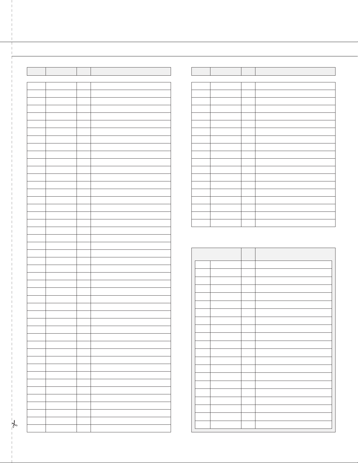
Part List
DO NOT RETURN PRODUCT IF YOU ARE MISSING PARTS. PLEASE CALL: 1 (800) 972-6130
No. Part # Qty Description
11006084 5Bolt, HexHd 1/4 x 3/4 SS
3 1005198 6 Nut, NylonLock, SS: 1/4”-20
41017543 1Plate, Linkage
51017501 1Bracket, Linkage
71017340 1Control Linkage Assembly
81001255 3Bolt, 1/4-20 x 1" HexHd,SS
91017551 1Bolt, HexHd 1/4-20 x 1.50
10 1017503 1Spring, Gate
11 1008431 1Rate Gate Link, Formed
12 1017580 1Plate, Hopper Bottom
13 1000203 1Hopper Bottom Bearing
14 1004880 4Bolt, HexHd 1/4 x 1/2 SS
15 1001521 2Guide, Rate Gate/Accuway
16 1000210 1Rate Gate
20 1000215 1Pine Tree Clip
21 1000211 1Dial Mount
22 1000213 1Dial, Plastic
23 1000198 2Felt Washer
24 1000051 1Spreading Spinner
25 1000844 1Agitator Blade
26 1017420 1Spinner Shaft, 50 Lb
27 1000054 1Roll Pin 1/8 x 7/8
28 1001301 23/8 Spinner Shaft Bushing
29 1001518 1Pinion Gear - Metal
30 1001299 2Gearbox Bushing 5/8"
31 1018126 1Axle, Wheel SS
32 1001304 1Dowel Pin, 3/16 x 1, SS
33 1001516 1Bevel Gear-metal
34 1005389 1Nylon Spacer, Pin Retain
35 1005336 1Gear Box Cover Front
36 1005368 1Grease Zerk 1/4 Drive IN
37 1017710 8Bolt, PhlpHd 10-24 x 5/8" SS
38 1005337 1Gear Box Cover Rear
39 1001308 8Nut, NylonLock, #10-24 SS
40 1000225 2Handle Grip
41 1019217 1Weldment, Handle, SS
42 1000000 1On-off Decal
51 1017502 1Linkage
52 1019222 1Handle, Lower, SS
57 1017504 2Cap, Plastic
58 L-1744-6 1Label, Serial#, Spyker
59 1019219 1Medium Frame Weldment, SS
60 1019223 1Stand, Med Frame, SS
63 1001607 2Wheel, 13”
64 F-283 2Bearing, Axle
67 1019225 1Manual
No. Part # Qty Description
68 1017577 1Cover, Hopper 50#
69 1017545 1Screen, 50#
70 1019224 1Hopper, 50# Blue
72 1017709 1Decal Spyker Ice
74 1000053 1Roll Pin, 1/8 x 3/4
75 1017730 1Spacer, Plastic
77 1017776 1Support Bracket
78 1001273 1Hairpin (299 Agitator), SS
79 1017626 3Label, Reflective
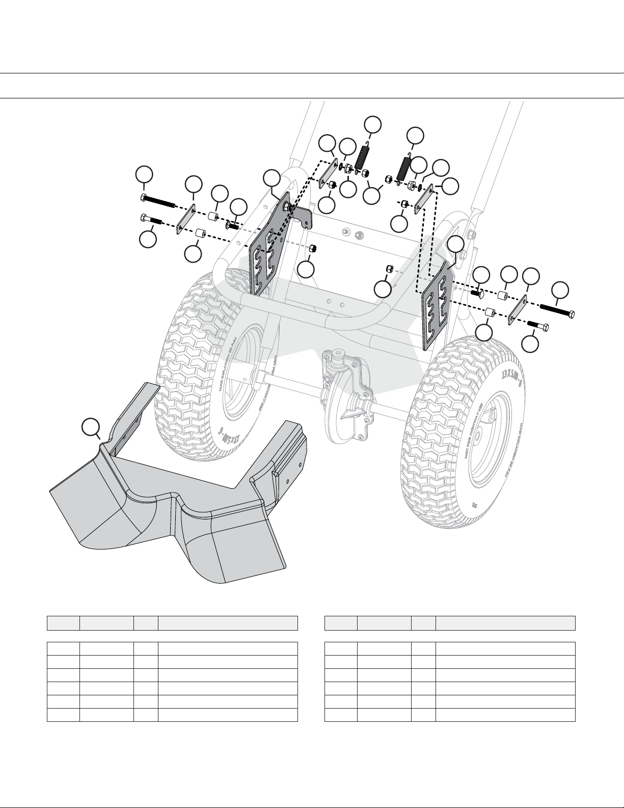
80 1019349 1Deflector
81 1018993 4 Spacer, Plastic
82 1019231-LH 1 Mounting Bracket, LH
83 1019231-RH 1 Mounting Bracket, RH
84 1018708 4 Stiffener Plate
86 1018738 2 Spring
87 1018740 2 External Tooth Lockwasher
88 1004975 2 Nut, 1/4-20 Hex Flange
89 1007386 2 Bolt, Carriage, SS: 1/4”-20 x 3/4”
90 1019001 2 Bolt, HexHd: 1/4”-20 x 1-3/4”
92 1018577 1 Parts Bag
21001554 9Washer, Nylon
31005198 23 Nut, NylonLock 1/4-20, SS
61001533 2Nylon Flange Bushing
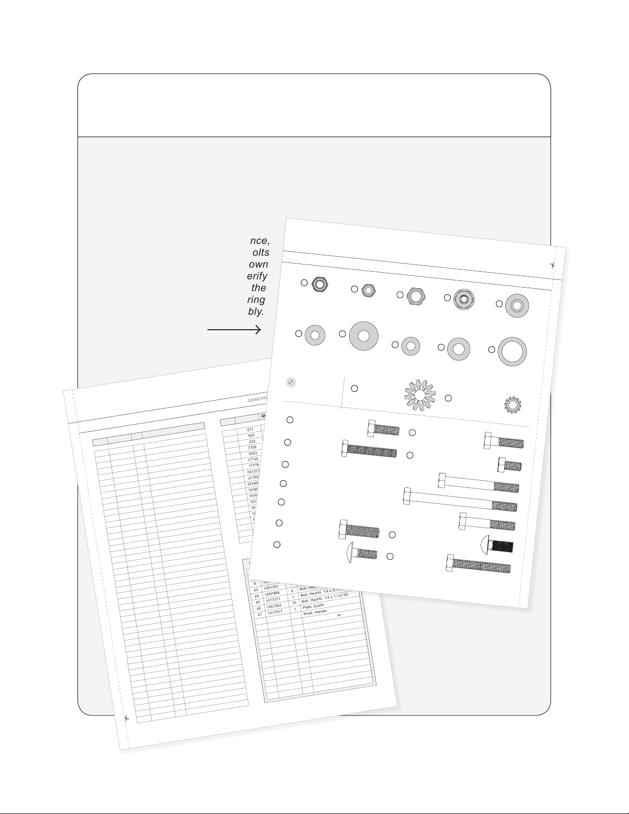
43 1001351 7Washer, 1/4" SS
44 1007888 4Bolt, HexHd, 1/4 x 2-1/4 SS
45 1017371 1Bolt, HexHd, 1/4 x 3-1/4 SS
46 1001262 10 Bolt, HexHd, 1/4 x 1-1/2 SS
47 1017617 1Plate, Guide
48 1007828 2Knob, Handle
49 1017346 1Spring, Control Lever
50 1017345 1Lever, Control
53 1001315 4Nut, NylonLock 5/16-18
54 45M1111SS 6 Washer, Flat, SS-5/16"
55 1008811 2Bolt, Hex 5/16-18 x 1 SS316
56 1017374 2Bolt, Carriage, 5/16 x 3/4
61 1005414 1Rue Ring Locking Pin
62 1001350 5Washer, Flat SS
65 1001274 1Clevis Pin, 3/16 x 1-3/4
66 1019596 1Cotter Ring
73 1017344 1Control Lever Stop
76 1017725 2 Lock Washer Ext/Int Tooth 5/16