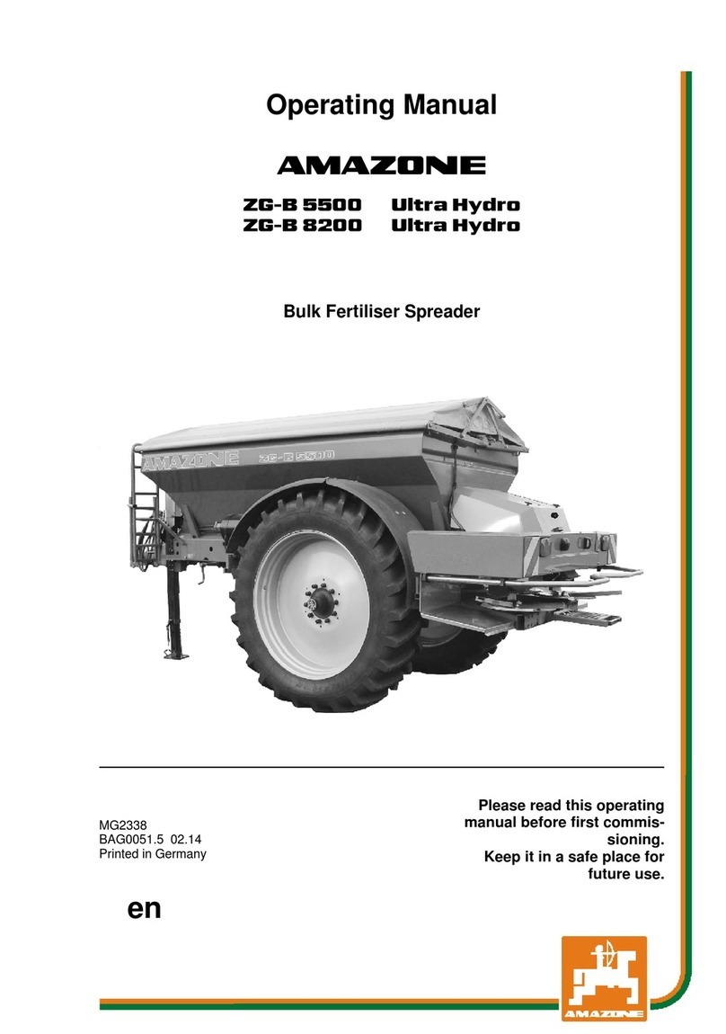
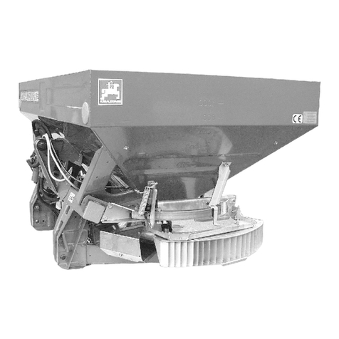
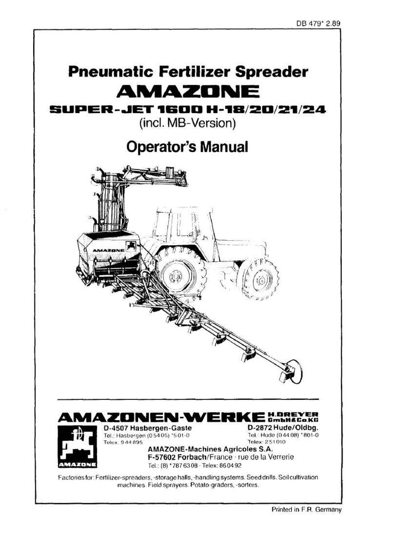
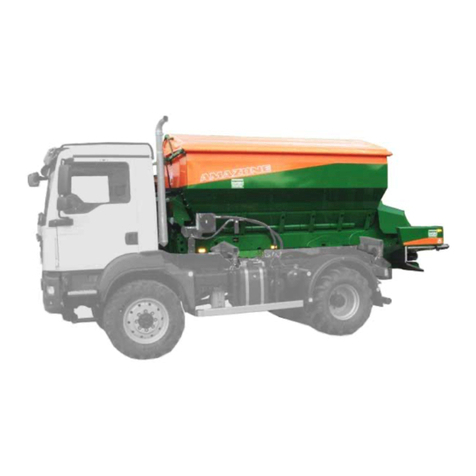
Amazone ZG-B 5500 Special User manual

Operating Manual
az
ZG-B 5500 Special / Super / Drive
ZG-B 8200 Special / Super / Drive
Trailed spreader
MG5160
BAG0003.18
01.19
Printed in Germany
Please read this operating
manual before first commi
s-
sioning.
Keep it in a safe place for
fu
ture use.
en

Reading the instruction
Manual and following it should seem to be in-
convenient and superfluous as it is not
enough to hear from others and to realize that a
machine is good, to buy it and to believe that now
everything should work by itself. The person in
question would not only harm himself but also
make the mistake of blaming the machine for pos-
sible failures instead of himself. In order to ensure
success one should enter the mind of a thing,
make himself familiar with every part of the ma-
chine and get acquainted with how it's handled.
Only in this way could you be satisfied both with
the machine and with yourself. This goal is the
purpose of this instruction manual.
Leipzig-Plagwitz 1872.
2 ZG-BBAG0003.18 01.19

Identification data
Identification data
Manufacturer:
AMAZONEN-WERKE
H. DREYER GmbH & Co. KG
Machine Ident. No.:
Type:
ZG-B Special,
ZG-B Super,
ZG-B Drive
Permissible system pressure (bar)
Maximum 10 bar
Year of manufacture:
Factory:
Basic weight (kg):
Approved total weight (kg):
Maximum load (kg):
Manufacturer's address
AMAZONEN-WERKE
H. DREYER GmbH & Co. KG
Postfach 51
D-49202
Tel.:
E-mail:
Hasbergen
+ 49 (0)5405 501-0
amazone@amazone.de
Spare part orders
Spare parts lists are freely accessible in the spare parts portal at
www.amazone.de.
Please send orders to your AMAZONE dealer.
Formalities of the operating manual
Document number:
MG5160
Compilation date:
01.19
Copyright AMAZONEN-WERKE H. DREYER GmbH & Co. KG, 2019
All rights reserved.
Reprinting, even of sections, only possible with the approval of AMA-
ZONEN-WERKE H. DREYER GmbH & Co. KG.
ZG-B BAG0003.18 01.19 3

Foreword
Foreword
Dear Customer,
You have chosen one of the quality products from the wide product
range of AMAZONEN-WERKE, H. DREYER GmbH & Co. KG. We
thank you for your confidence in our products.
On receiving the machine, check to see if it was damaged during
transport or if parts are missing. Using the delivery note, check that
the machine was delivered in full including the ordered special equip-
ment. Damage can only be rectified if problems are signalled immedi-
ately!
Before first commissioning, read and understand this operating man-
ual, and particularly the safety information. Only after careful reading
will you be able to benefit from the full scope of your newly purchased
machine.
Please ensure that all the machine operators have read this operating
manual before commissioning the machine.
Should you have any questions or problems, please consult this op-
erating manual or contact your local service partner.
Regular maintenance and timely replacement of worn or damaged
parts increases the lifespan of your machine.
User evaluation
Dear Reader,
We update our operating manuals regularly. Your suggestions for
improvement help us to create ever more user-friendly manuals.
AMAZONEN-WERKE
H. DREYER GmbH & Co. KG
Postfach 51
D-49202
Tel.:
E-mail:
Hasbergen
+ 49 (0)5405 501-0
amazone@amazone.de
4 ZG-BBAG0003.18 01.19

Table of Contents
1User Information..........................................................................................9
1.1 Purpose of the document.........................................................................................................9
1.2 Locations in the operating manual...........................................................................................9
1.3 Diagrams used.........................................................................................................................9
2General safety instructions.......................................................................10
2.1 Obligations and liability..........................................................................................................10
2.2 Representation of safety symbols..........................................................................................12
2.3 Organisational measures.......................................................................................................13
2.4 Safety and protection equipment...........................................................................................13
2.5 Informal safety measures.......................................................................................................13
2.6 Operator training....................................................................................................................14
2.7 Safety measures in normal operation....................................................................................14
2.8 Danger from residual energy .................................................................................................15
2.9 Maintenance and repair work, fault elimination .....................................................................15
2.10 Design changes .....................................................................................................................15
2.10.1 Spare and wear parts and auxiliary materials........................................................................16
2.11 Cleaning and disposal............................................................................................................16
2.12 Operator workstation..............................................................................................................16
2.13 Warning symbols and other labels on the machine...............................................................17
2.13.1 Positions of warning symbols and other labels......................................................................18
2.14 Dangers if the safety information is not observed..................................................................24
2.15 Safety-conscious working......................................................................................................24
2.16 Safety information for the operator ........................................................................................25
2.16.1 General safety and accident prevention information .............................................................25
2.16.2 Hydraulic system....................................................................................................................28
2.16.3 Electrical system....................................................................................................................29
2.16.4 Coupled machines .................................................................................................................29
2.16.5 Brake system .........................................................................................................................30
2.16.6 Tyres ......................................................................................................................................31
2.16.7 Fertiliser spreader operation..................................................................................................31
2.16.8 Universal joint shaft operation................................................................................................32
2.16.9 Cleaning, maintenance and repairs.......................................................................................33
3Loading.......................................................................................................34
4Product description...................................................................................35
4.1 Overview of subassemblies...................................................................................................35
4.2 Safety and protection equipment...........................................................................................36
4.3 Supply lines between the tractor and the machine................................................................37
4.4 Transportation equipment......................................................................................................37
4.5 Intended use ..........................................................................................................................38
4.6 Danger areas .........................................................................................................................39
4.7 Rating plate and CE mark......................................................................................................40
4.8 Technical data........................................................................................................................41
4.8.1 Payload ..................................................................................................................................42
4.9 Necessary tractor equipment.................................................................................................44
4.10 Noise production data............................................................................................................44
5Structure and function ..............................................................................45
5.1 Air-pressure brake system.....................................................................................................47
5.1.1 Coupling the brake system ....................................................................................................48
5.1.2 Uncoupling the brake system.................................................................................................49
5.2 Hydraulic service brake system.............................................................................................50
5.2.1 Coupling the hydraulic service brake system ........................................................................50
5.2.2 Uncoupling the hydraulic service brake system.....................................................................50
ZG-B BAG0003.18 01.19 5

Table of Contents
5.2.3 Emergency brake.................................................................................................................. 50
5.3 Parking brake ........................................................................................................................ 52
5.4 Overrun brake with automatic reversing ............................................................................... 53
5.5 Wheel chocks........................................................................................................................ 53
5.6 Safety chain for implements without brake system............................................................... 54
5.7 Immobiliser for towing device................................................................................................ 54
5.8 Drawbars............................................................................................................................... 55
5.9 Hydraulic connections........................................................................................................... 56
5.9.1 Coupling the hydraulic hose lines ......................................................................................... 57
5.9.2 Decoupling the hydraulic hose lines...................................................................................... 58
5.10 Hyclick electro-hydraulic preselection................................................................................... 58
5.11 PTO shaft.............................................................................................................................. 59
5.11.1 Coupling the PTO shaft......................................................................................................... 61
5.11.2 Uncoupling the PTO shaft..................................................................................................... 62
5.12 Main shutter slide .................................................................................................................. 63
5.13 Double shutter....................................................................................................................... 64
5.14 Fertiliser chain rake (option).................................................................................................. 65
5.14.1 Chain rake, removable.......................................................................................................... 65
5.14.2 Chain rake on the double shutter.......................................................................................... 65
5.15 Spreading granular fertiliser with spreading discs OM.......................................................... 67
5.16 Spreading lime with lime spreading discs............................................................................. 69
5.17 Spreading granulated fertiliser with lime spreading discs..................................................... 70
5.18 Spreading of bone meal with bone meal spreading discs..................................................... 71
5.19 Spreading disc holder............................................................................................................ 71
5.20 Boundary and side spreading with the boundary spreading Limiter..................................... 72
5.21 Conveyor belt........................................................................................................................ 72
5.21.1 Belt conveyor driven hydraulically......................................................................................... 73
5.21.2 Ground wheel drives of conveyor belt................................................................................... 74
5.22 Foldable ladder...................................................................................................................... 75
5.23 Stand..................................................................................................................................... 76
5.24 Charging sieves..................................................................................................................... 77
5.25 Swivelable hopper cover (optional)....................................................................................... 77
5.26 Camera system..................................................................................................................... 77
5.27 Setting chart .......................................................................................................................... 78
5.28 ZG-B Drive ............................................................................................................................ 80
5.28.1 AMATRON 3 in-cab terminal................................................................................................. 80
5.28.2 Control block and machine computer.................................................................................... 81
5.28.3 TrailTron tracking control ...................................................................................................... 81
5.29 Weighing technology with weighing terminal ........................................................................ 84
5.29.1 Tare the weighing equipment................................................................................................ 84
5.29.2 Menu layout........................................................................................................................... 85
5.30 AMALOG+as hectare counter for ZG-B Super..................................................................... 87
5.30.1 Product description................................................................................................................ 87
5.30.2 Work display Starting work................................................................................................. 88
5.30.3 Installing the terminal ............................................................................................................ 89
5.30.4 Settings ................................................................................................................................. 90
5.30.5 Calibration value.................................................................................................................... 91
5.30.6 EasyCheck ............................................................................................................................ 93
5.30.7 Mobile test rig........................................................................................................................ 93
6Commissioning ......................................................................................... 94
6.1 Checking the suitability of the tractor .................................................................................... 95
6.1.1 Calculating the actual values for the total tractor weight, tractor axle loads and load
capacities, as well as the minimum ballast ........................................................................... 95
6.1.2 Requirements for tractor operation with attached machines................................................. 99
6.1.3 Machines without their own brake system .......................................................................... 102
6 ZG-BBAG0003.18 01.19
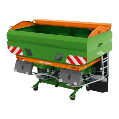
Table of Contents
6.2 Adjusting the length of the PTO shaft to the tractor.............................................................103
6.3 Securing the tractor / machine against unintentional start-up and rolling............................105
6.4 Fitting wheels.......................................................................................................................106
6.5 Initial operation of service brake system..............................................................................107
6.6 Adjusting the height of the machine drawbar.......................................................................107
6.7 Adjusting the hydraulic system with the system setting screw............................................108
6.8 TrailTron position encoder ...................................................................................................110
7Coupling and uncoupling the machine..................................................111
7.1 Coupling the machine..........................................................................................................111
7.2 Uncoupling the machine ......................................................................................................113
7.2.1 Manoeuvring the uncoupled machine..................................................................................114
8Adjustments.............................................................................................115
8.1 Setting the spread rate.........................................................................................................116
8.1.1 The quantity factor can be taken from the setting chart ......................................................117
8.1.2 Determining the setting value using a sliding ruler..............................................................118
8.1.3 Setting the spread rate via the main shutter slide................................................................119
8.1.4 Setting the belt speed..........................................................................................................120
8.2 Spread rate control mineral fertiliser calibration ..................................................................121
8.2.1 Arrangement for the spread rate check ...............................................................................121
8.2.2 Spread rate check by driving a test distance.......................................................................122
8.2.3 Stationary spread rate check...............................................................................................123
8.3 Setting the spreading discs OM...........................................................................................124
8.3.1 Setting the working width.....................................................................................................124
8.3.2 Adjusting the spreading vane positions ...............................................................................125
8.3.3 Checking the working width and lateral distribution.............................................................127
8.3.4 Late top dressing .................................................................................................................128
8.3.5 Setting the funnel chute.......................................................................................................128
8.4 Boundary, ditch and side spreading ....................................................................................129
8.4.1 Boundary and side spreading using the Limiter ZG-B boundary spread deflector..............130
9Transportation .........................................................................................133
10 Use of the machine..................................................................................135
10.1 Filling the machine...............................................................................................................138
10.2 Emptying the machine while stationary ...............................................................................139
10.3 Spreading operation.............................................................................................................140
10.4 Recommendation for working in headlands.........................................................................142
11 Faults........................................................................................................143
12 Cleaning, maintenance and repairs........................................................145
12.1 Cleaning...............................................................................................................................147
12.2 Lubrication point overview ...................................................................................................148
12.3 Maintenance schedule – overview.......................................................................................151
12.4 Exchanging the spreading discs..........................................................................................153
12.5 Replacing the spreading vanes and swivel vanes...............................................................154
12.5.1 Replacing the spreading vanes............................................................................................154
12.5.2 Replacing the swivel vanes OM...........................................................................................156
12.6 Belt conveyor with automatic belt control ............................................................................157
12.7 Check the coupling device...................................................................................................158
12.8 Axle and brake.....................................................................................................................159
12.8.1 Inspection instructions for the dual circuit service brake system.........................................164
12.9 Parking brake.......................................................................................................................165
12.10 Tyres / wheels......................................................................................................................166
12.10.1 Tyre pressures.....................................................................................................................166
12.10.2 Fitting tyres...........................................................................................................................167
ZG-B BAG0003.18 01.19 7

Table of Contents
12.11 Hydraulic system................................................................................................................. 168
12.11.1 Labelling hydraulic hose lines ............................................................................................. 169
12.11.2 Maintenance intervals ......................................................................................................... 170
12.11.3 Inspection criteria for hydraulic hose lines.......................................................................... 170
12.11.4 Installation and removal of hydraulic hose lines ................................................................. 171
12.11.5 Mounting hose fittings with O-rings and sleeve nuts........................................................... 171
12.12 Hydraulic fluid filter.............................................................................................................. 172
12.13 Cleaning the solenoid valves .............................................................................................. 172
12.14 Gearbox............................................................................................................................... 173
12.15 Electric lighting system........................................................................................................ 173
12.16 Screw tightening torques..................................................................................................... 174
13 Hydraulic diagram................................................................................... 175
8 ZG-BBAG0003.18 01.19

User Information
1 User Information
The User Information section provides information on use of the oper-
ating manual.
1.1 Purpose of the document
This operating manual
•Describes the operation and maintenance of the machine.
•Provides important information on safe and efficient handling of
the machine.
•Is a component part of the machine and should always be kept
with the machine or the traction vehicle.
•Keep it in a safe place for future use.
1.2 Locations in the operating manual
All the directions specified in the operating manual are always seen
from the direction of travel.
1.3 Diagrams used
Operator control action and responses
Actions to be carried out by the operator are given as a numbered list.
It is important that the sequence of steps is observed. The responses
for each operator control action are given by an arrow. Example:
1. Operator control action step 1
→Machine response to operator control action 1
2. Operator control action step 2
Lists
Lists without an essential order are shown as a list with bullets. Ex-
ample:
•Point 1
•Point 2
Number items in diagrams
Numbers in round bracket refer to items in diagrams. The first number
refers to the diagram and the second number to the item in the figure.
Example: (Fig. 3/6)
•Figure 3
•Item 6
ZG-B BAG0003.18 01.19 9

General safety instructions
2 General safety instructions
This section contains important information on safe operation of the
machine.
2.1 Obligations and liability
Comply with the instructions in the operating manual
Knowledge of the basic safety information and safety regulations is a
basic requirement for safe handling and fault-free machine operation.
Obligations of the operator
The operator is obliged only to let those people work with/on the ma-
chine who
•Are aware of the basic workplace safety information and acci-
dent prevention regulations.
•Have been trained in working with/on the machine.
•Have read and understood this operating manual.
The operator is obliged
•To keep all the warning symbols on the machine in a legible
state.
•To replace damaged warning symbols.
Obligations of the user
Before starting work, anyone charged with working with/on the ma-
chine is obliged
•To comply with the basic workplace safety instructions and acci-
dent prevention regulations.
•To read and follow the "General safety information" section of
this operating manual.
•To read the section "Warning symbols and other labels on the
machine" (page 17) of this operating manual and to follow the
safety instructions represented by the warning symbols when
operating the machine.
•If you still have queries, please contact the manufacturer.
10 ZG-BBAG0003.18 01.19

General safety instructions
Risks in handling the machine
The machine has been constructed to the state-of-the art and the
recognised rules of safety. However, there may be risks and re-
strictions which occur when operating the machine
•For the health and safety of the operator or third persons,
•For the machine,
•For other goods.
Only use the machine
•For the purpose for which it was intended.
•In a perfect state of repair.
Eliminate any faults immediately which could impair safety.
Guarantee and liability
Our "General conditions of sales and delivery" are always applicable.
These shall be available to the operator, at the latest on the comple-
tion of the contract. Guarantee and liability claims for damage to peo-
ple or goods will be excluded if they can be traced back to one or
more of the following causes:
•Improper use of the machine.
•Improper installation, commissioning, operation and mainte-
nance of the machine.
•Operation of the machine with defective safety equipment or
improperly attached or non-functioning safety equipment.
•Non-compliance with the instructions in the operating manual
regarding commissioning, operation and maintenance.
•Independently-executed design changes to the machine.
•Insufficient monitoring of machine parts which are subject to
wear.
•Improperly executed repairs.
•Disasters through the impact of foreign bodies and acts of God.
ZG-B BAG0003.18 01.19 11

General safety instructions
2.2 Representation of safety symbols
Safety instructions are indicated by the triangular safety symbol and
the highlighted signal word. The signal word (danger, warning, cau-
tion) describes the severity of the risk, and carries the following mean-
ing:
DANGER
Indicates an immediate high risk which will result in death or
serious physical injury (loss of body parts or long term damage)
if not avoided.
If the instructions are not followed, then this will result in imme-
diate death or serious physical injury.
WARNING
Indicates a medium risk, which could result in death or (serious)
physical injury if not avoided.
If the instructions are not followed, then this may result in death
or serious physical injury.
CAUTION
Indicates a low risk which could cause minor or medium level
physical injury or damage to property if not avoided.
IMPORTANT
Indicates an obligation to special behaviour or an activity re-
quired for proper machine handling.
Non-compliance with these instructions can cause faults on the
machine or in the environment.
NOTE
Indicates handling tips and particularly useful information.
These instructions will help you to use all the functions of your
machine to the optimum.
12 ZG-BBAG0003.18 01.19

General safety instructions
2.3 Organisational measures
The operator must provide the necessary personal protective equip-
ment as per the information provided by the manufacturer of the crop
protection agent to be used, such as:
•Chemical-resistant gloves,
•Chemical-resistant overalls,
•Water-resistant footwear,
•A face mask,
•Breathing protection,
•Safety glasses,
•Skin protection agents, etc.
The operating manual
•Must always be kept at the place at which the machine is oper-
ated.
•Must always be easily accessible for the operator and mainte-
nance personnel.
Check all the available safety equipment regularly.
2.4 Safety and protection equipment
Before each commissioning of the machine, all the safety and protec-
tion equipment must be properly attached and fully functional. Check
all the safety and protection equipment regularly.
Faulty safety equipment
Faulty or disassembled safety and protection equipment can lead to
dangerous situations.
2.5 Informal safety measures
As well as all the safety information in this operating manual, comply
with the general, national regulations pertaining to accident prevention
and environmental protection.
When driving on public roads and routes, then you should comply with
the statutory road traffic regulations.
ZG-B BAG0003.18 01.19 13

General safety instructions
2.6 Operator training
Only those people who have been trained and instructed may work
with/on the machine. The operator must clearly specify the responsi-
bilities of the people charged with operation and maintenance work.
People being trained may only work with/on the machine under the
supervision of an experienced person.
People
Activity
Person special-
ly trained for the
activity1)
Trained opera-
tor2) Person with specialist
training
(specialist workshop*)3)
Loading/Transport X X X
Commissioning -- X --
Set-up, tool installation -- -- X
Operation -- X --
Maintenance -- -- X
Troubleshooting and fault elimina-
tion X -- X
Disposal X -- --
Legend: X..permitted --..not permitted
1) A person who can assume a specific task and who can carry out
this task for an appropriately qualified company.
2) Instructed persons are those who have been instructed in their
assigned tasks and in the possible risks in the case of improper
behaviour, have been trained if necessary, and have been in-
formed about the necessary protective equipment and
measures.
3) People with specialist technical training shall be considered as a
specialist. Due to their specialist training and their knowledge of
the appropriate regulations, they can evaluate the work with
which they have been charged and detect possible dangers.
Comment:
A qualification equivalent to specialist training can be obtained
through long term activity in the appropriate field of work.
Only a specialist workshop may carry out maintenance and repair
work on the machine if such work is additionally marked "Workshop
work". The personnel of a specialist workshop shall possess the ap-
propriate knowledge and suitable aids (tools, lifting and support
equipment) for carrying out the maintenance and repair work on the
machine in a way which is both appropriate and safe.
2.7 Safety measures in normal operation
Only operate the machine if all the safety and protection equipment is
fully functional.
Check the machine at least once a day for visible damage and check
the function of the safety and protection equipment.
14 ZG-BBAG0003.18 01.19

General safety instructions
2.8 Danger from residual energy
Note that there may be residual mechanical, hydraulic, pneumatic and
electrical/electronic energy on the machine.
Use appropriate measures to inform the operatin
g personnel. You can
find detailed information in the relevant sections of this operating
manual.
2.9 Maintenance and repair work, fault elimination
Carry out prescribed setting, maintenance and inspection work in
good time.
Secure all media such as compressed air and the hydraulic system
against unintentional start-up.
Carefully fix and secure larger subassemblies to lifting gear when
carrying out replacement work.
Schraubverbindungen regelmäßig auf festen Sitz kontrollieren und
gegebenenfalls nachziehen.
Nach Beendigung der Wartungsarbeiten Sicherheitseinrichtungen auf
Funktion überprüfen.
2.10 Design changes
You may make no changes, expansions or modifications to the ma-
chine without the approval of AMAZONEN-WERKE. This is also valid
when welding support parts.
Any expansion or modification work shall require the written approval
of AMAZONEN-WERKE. Only use the modification and accessory
parts released by AMAZONEN-WERKE, so that the type approval
remains valid according to the national and international regulations.
Vehicles with an official type approval or with equipment connected to
a vehicle with a valid type approval or approval for road transport
according to the German road traffic regulations must be in the state
specified by the approval.
WARNING
Risk of contusions, cuts, dragging, catching or knocks from
support parts.
It is forbidden to:
•Drill holes in the frame or on the running gear.
•Increase the size of existing holes on the frame or the running
gear.
•Weld support parts.
ZG-B BAG0003.18 01.19 15

General safety instructions
2.10.1 Spare and wear parts and auxiliary materials
Immediately replace any machine parts which are not in a perfect
state.
Only use AMAZONE spare and wear parts released by AMAZONEN-
WERKE, so that the type approval remains valid according to the
national and international regulations. The use of wear and spare
parts from third parties does not guarantee that they have been con-
structed in a way as to meet the requirements placed on them.
AMAZONEN-WERKE shall accept no liability for damage caused by
the use of unreleased spare and wear parts or auxiliary materials.
2.11 Cleaning and disposal
Handle and dispose of any materials used carefully, in particular
•When carrying out work on lubrication systems and equipment
and
•When cleaning using solvents.
2.12 Operator workstation
The machine may only be operated by one person sitting in the driv-
er's seat of the tractor.
16 ZG-BBAG0003.18 01.19

General safety instructions
2.13 Warning symbols and other labels on the machine
Always keep all the warning symbols on the machine clean and in a
legible state. Replace illegible warning symbols. You can obtain the
warning symbols from your dealer using the order number (e.g. MD
075).
Warning symbols - structure
Warning symbols indicate dangers on the machine and warn against
residual dangers. At these points, there are permanent or unexpected
dangers.
A warning symbol consists of two fields:
Field 1
is a symbol describing the danger, surrounded by triangular safety
symbol.
Field 2
is a symbol showing how to avoid the danger.
Warning symbols - explanation
The column Order number and explanation provides an explanation
of the neighbouring warning symbol. The description of the warning
symbols is always the same and specifies, in the following order:
1. A description of the danger.
For example: danger of cutting!
2. The consequence of non-compliance with risk avoidance instruc-
tions.
For example: causes serious injuries to fingers or hands.
3. Instructions for avoiding the danger.
For example: only touch machine parts when they have come to
a complete standstill.
ZG-B BAG0003.18 01.19 17

General safety instructions
2.13.1 Positions of warning symbols and other labels
The following diagrams show the arrangement of the warning symbols
on the machine.
Fig.
1
Fig.
2
18 ZG-BBAG0003.18 01.19
General safety instructions
Fig. 3
Fig.
4
ZG-B BAG0003.18 01.19 19

General safety instructions
Order number and explanation
Warning symbols
MD 075
Risk of fingers and hands being cut or cut off
by accessible, moving parts involved in the
work process.
This danger can cause extremely serious injuries
and the loss of body parts.
•Never reach into the danger area when the
tractor engine is running with PTO shaft /
hydraulic / electronics system connected.
•Wait for all moving machine parts to come
to a complete standstill before reaching into
the danger area.
MD 076
Danger of your hand or arm being drawn in or
caught by power-
driven, unprotected chain or
belt drives.
This danger causes serious injuries, including
loss of body parts such as the hand or arm.
Never open or remove protective equipment from
chains or belt drives,
•while the tractor engine is running and the
PTO shaft is connected / hydraulic drive is
engaged
•or the ground wheel drive is moving
MD 078
Risk of crushing fingers or hands by acces-
sible moving machine parts.
This danger causes serious injuries, including
loss of body parts such as fingers or hand.
Never reach into the danger area while the trac-
tor engine is running and the PTO shaft / hydrau-
lic system is connected.
MD 082
Risk of falling for personnel riding on treads
or platforms.
This danger can cause extremely serious and
potentially fatal injuries.
It is forbidden to ride on the machine or climb the
machine when it is running. This also applies to
machines with treads or platforms.
Make sure that nobody is riding on the machine.
20 ZG-BBAG0003.18 01.19
This manual suits for next models
5
Table of contents
Other Amazone Spreader manuals

Amazone
Amazone ZG-B 5500 Ultra Hydro User manual

Amazone
Amazone ZA-TS Super User manual

Amazone
Amazone E+S User manual

Amazone
Amazone ZA-TS Super User manual

Amazone
Amazone IceTiger Installation instructions

Amazone
Amazone Limiter M User manual

Amazone
Amazone ZA-M User manual

Amazone
Amazone ZA-X User manual

Amazone
Amazone ZA-M 1002 Special Easy User manual

Amazone
Amazone JET 1203 User manual