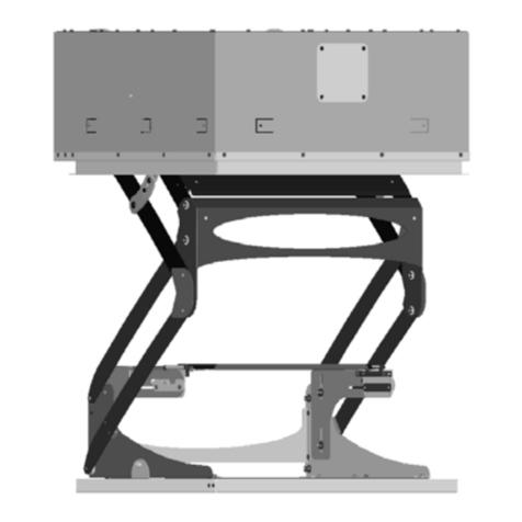
CHIEF SLB-9000 User manual

S
LB-9000
C
eiling Bracket
BEFORE YOU BEGIN
•CAUTION: To prevent damage to the SLB-9000, which could affect or void the Factory warranty, thoroughly study all
instructions and illustrations before you begin to install the SLB-900. Pay particular attention to the “Important Pre-
cautions” on Page 1.
• The maximum weight to be installed on the SLB-9000 is 50 pounds (22.68 Kg).
• If you have any questions about this assembly, contact Chief Manufacturing at 1-800-582-6480.
I N S T R U C T I O N M A N U A L
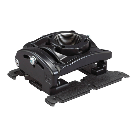
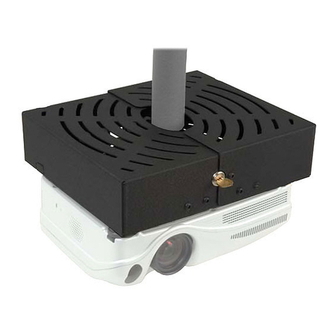
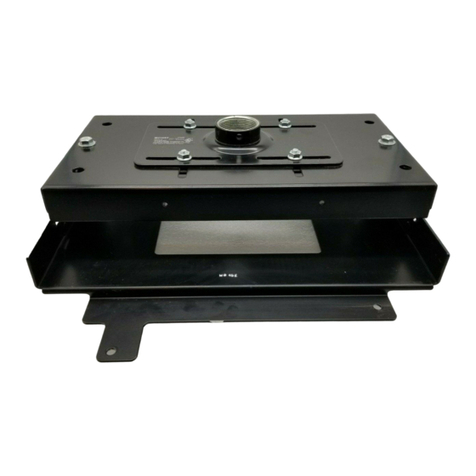
The Chief SLB Projector Mount provides a unique, simplified
method of mounting your LCD/DLP projector. This low pro-
file design offers three easy mounting methods (1”NPT, flush
or threaded rod); roll, pitch and yaw adjustment; and cable
management system; that allow quick projector disconnect
without loss of registration.
The mount is constructed of heavy gauge steel and designed to
ensure proper projector ventilation. Fast and precise image reg-
istration is achieved through the easy roll, pitch and yaw
adjustments built into the Chief SLB Projector Mount.
Please read and follow these installation instructions carefully
before installing products.
LOGO
CHIEF MANUFACTURING INC.
1-800-582-6480 952-894-6280 FAX 952-894-6918
12800 HIGHWAY 13 SOUTH, SUITE 500
SAVAGE, MINNESOTA 55378 USA
PART NO. 8802-000118 (Rev. A)
2003Chief Manufacturing
www.chiefmfg.com
Printed in USA 12-03

Instruction Manual SLB-9000
1
IMPORTANT WARNINGS AND CAUTIONS!
WARNING: A WARNING alerts you to the possibility of serious injury or death if you do not follow the instructions.
CAUTION: ACAUTION alerts you to the possibility of damage or destruction of equipment if you do not follow the cor-
responding instructions.
•WARNING: Improper installation can result in serious personal injury! Make sure that the structural members can
support a redundant weight factor five times the total weight of the equipment. If the structure can not
support this weight, reinforce the structure before installing the SLB-9000.
•WARNING: You must use proper attaching hardware and installation procedures. Failure to use proper attaching
hardware and installation procedures may result in equipment damage or serious personal injury.
• WARNING: Be aware of the potential for personal injury or damage to the unit if it is not adequately mounted.
•WARNING: The installer is responsible for verifying that the mounting surface structural members to which the
mount is anchored will safely support the combined load of all attached components or other equip-
ment.
•CAUTION: Inspect the unit for shipping damage.
•CAUTION: When attaching the mount, be careful not to overtighten mounting screws.
•CAUTION: Changes or modifications not approved by Chief Manufacturing could void user’s warranty.
TOOLS REQUIRED FOR INSTALLATION
• Phillips screwdrivers, No. 1 and No. 2
NOTE: Other tools may be required depending on the
method of installation.

2
Instruction Manual SLB-9000
CONTENTS
INSPECT THE BRACKET AND
ATTACHING HARDWARE BEFORE
INSTALLING ...................................................... 3
SELECT PROJECTOR MODEL AND
DETERMINE PARTS .......................................... 3
BRACKET INSTALLATION PROCEDURES .. 5
Group A Installation Procedures: ..................... 5
Group B Installation Procedures: ..................... 5
Group C Installation Procedures: ..................... 6
Group D Installation Procedures: ..................... 6
Group E Installation Procedures: ..................... 7
PARTS .................................................................. 8

Instruction Manual SLB-9000
3
INSPECT THE BRACKET AND ATTACHING HARDWARE BEFORE INSTALLING
1. Carefully inspect the SLB-9000 for shipping damage. If any
damage is apparent, call your carrier claims agent and do not
continue with the installation until the carrier has reviewed the
damage.
NOTE: Read all instructions before starting installation.
2. Lay out components to ensure you have all the required parts
before proceeding (see “PARTS” on page 8).
SELECT PROJECTOR MODEL AND DETERMINE PARTS
This interface bracket is designed to fit a wide variety of projector models. Study the following information carefully to select the
proper hardware and assembly procedures for your specific projector model. To determine the correct hardware and procedures,
perform the following:
1. Using Table 1 on page 4, locate your projector model.
2. Note and record the group letter for your projector model.
NOTE: Not all hardware will be used for every installation. Do not discard extra hardware until installation is complete.
3. Using the group number determined in Step 2, proceed to
“BRACKET INSTALLATION PROCEDURES” on page 5
and follow the instructions for your projector model

4
Instruction Manual SLB-9000
.
Manufacturer Model
Group
Manufacturer Model
Group
A + K AstroBeam S120 DGeha Compact 280 A
A + K AstroBeam S230 AGeha Compact 290 C
A + K AstroBeam X120 DGeha Compact 690 B
A + K AstroBeam X201 EIBM
Conference
Room
A
A + K AstroBeam X211 EIBM iL C200 A
A + K AstroBeam X220 CIBM iL C300 C
A + K AstroBeam X230 AIBM iL V200 A
A + K AstroBeam X310 BIBM iL V300 B
A + K AstroBeam X311 BIBM Value Based A
ASK C100 EInfocus LP 240 D
ASK C105 EInfocus LP 250 D
ASK C200 CInfocus LP 340 A
ASK C300 BInfocus LP 340B A
ASK C40 DInfocus LP 350 A
ASK C420 CInfocus
LP
500
SERIES
A
ASK C50 DInfocus LP 530 A
ASK C80 EInfocus LP 650 C
ASK C90 EInfocus LP 690 E
ASK C95 EInfocus LP 790 B
Boxlight 12SF AInfocus LP 790HB B
Boxlight CD-454m AInfocus LP 820 C
Boxlight CD-455m AInfocus LS 110 A
Boxlight CD-555m AInfocus
Screenplay
110
A
Boxlight CD-600m AInfocus
Screenplay
4800
B
Boxlight CD-750m AInfocus
Screenplay
5700
C
Boxlight CD-850m CInfocus
Screenplay
7200
C
Boxlight CD-875m CInfocus
Screenplay
7205
C
Boxlight Cinema 12SF AInfocus X1 B
Boxlight SP-45m DKnoll HD-101 B
Boxlight XP-55m DKnoll HD-110 A
Dataview E200 EKnoll HD-177 C
Dataview E220 EKnoll HD-272 C
Dataview E221 EKnoll HT-202 A
Dataview E231 EProxima DP 2000s D
Dataview M320 BProxima DP 2000x D
Dream Vision Dream Weaver CProxima DP 6150 E
Dream Vision Dream Weaver II CProxima DP 6155 E
Dukane ImagePro 7100HC BProxima DP 6500x C
Dukane ImagePro 8043A DProxima DP 8000 B
Dukane ImagePro 8048 AProxima DP 8000HB B
Dukane ImagePro 8750 AProxima DP 8200x C
Dukane ImagePro 8753A DToshiba TDP-MT100 B
Dukane ImagePro 8757 CToshiba TDP-MT5 A
Geha Compact 105 DToshiba TDP-MT8U C
Geha Compact 107 BToshiba TDP-S2 A
Geha Compact 205 DToshiba TDP-S2V A
Geha Compact 210 Plus EToshiba TDP-S3 A
Geha Compact 211 Plus EToshiba TDP-T1 A
Geha Compact 280 AToshiba TDP-T3 A
Geha Compact 290 CYokogawa D-1500X E

Instruction Manual SLB-9000
5
BRACKET INSTALLATION PROCEDURES
Group A Installation Procedures:
1. Turn your projector over and place it on a clean, flat, suitable
surface.
2. Find and open the hardware kit (parts) for your projector model
(see “SELECT PROJECTOR MODEL AND DETERMINE
PARTS” on page 3).
3. Place a 3/8” X 1/2” Nylon spacer over each threaded insert in
the bottom of your projector.
4. Using Figure 1, find the proper mounting holes in SLB-9000
for your projector.
5. Place the SLB-9000 on the 3 Nylon spacers, aligning the
proper mounting holes in SLB-9000 with the Nylon spacers.
CAUTION: When attaching the mount, be careful not to over-
tighten mounting screws.
6. Secure the SLB-9000 to your projector using three M4-20mm
pan-head screws and three M4 flat washers.
7. See InFocus Universal Projector Mount Instructions.
Group B Installation Procedures:
1. Turn your projector over and place it on a clean, flat, suitable
surface.
2. Find and open the hardware kit (parts) for your projector model
(see “SELECT PROJECTOR MODEL AND DETERMINE
PARTS” on page 3).
3. Place a 3/8” X 1/2” Nylon spacer over each threaded insert in
the bottom of your projector.
4. Using Figure 2, find the proper mounting holes in SLB-9000
for your projector.
5. Place the SLB-9000 on the 3 Nylon spacers, aligning the
proper mounting holes in SLB-9000 with the Nylon spacers.
CAUTION: When attaching the mount, be careful not to over-
tighten mounting screws.
6. Secure the SLB-9000 to your projector using two M4-20mm
pan-head screws, one 20mm flat head screw, and two M4 flat
washers.
7. See RPA and/or Smart-Lift Instructions.
Figure 1. Group A Hole Alignment
Figure 2. Group B Hole Alignment

6
Instruction Manual SLB-9000
Group C Installation Procedures:
1. Turn your projector over and place it on a clean, flat, suitable
surface.
2. Find and open the hardware kit (parts) for your projector model
(see “SELECT PROJECTOR MODEL AND DETERMINE
PARTS” on page 3).
3. Place a 3/8” X 1/2” Nylon spacer over each threaded insert in
the bottom of your projector.
4. Using Figure 3, find the proper mounting holes in SLB-9000
for your projector.
5. Place the SLB-9000 on the 3 Nylon spacers, aligning the
proper mounting holes in SLB-9000 with the Nylon spacers.
CAUTION: When attaching the mount, be careful not to over-
tighten mounting screws.
6. Secure the SLB-9000 to your projector using three M4-20mm
pan-head screws, three M4 flat washers, and three 3/8” X 1/2”
Nylon spacers provided.
7. See RPA and/or Smart-Lift Instructions.
Group D Installation Procedures:
1. Turn your projector over and place it on a clean, flat, suitable
surface.
2. Find and open the hardware kit (parts) for your projector model
(see “SELECT PROJECTOR MODEL AND DETERMINE
PARTS” on page 3).
3. Place a 3/8” X 1/2” Nylon spacer over each threaded insert in
the bottom of your projector.
4. Using Figure 4, find the proper mounting holes in SLB-9000
for your projector.
5. Place the SLB-9000 on the 3 Nylon spacers, aligning the
proper mounting holes in SLB-9000 with the Nylon spacers.
CAUTION: When attaching the mount, be careful not to over-
tighten mounting screws.
6. Secure the SLB-9000 to your projector using two M4-20mm
pan-head screws, one 20mm flat head screw, and two M4 flat
washers.
7. See RPA and/or Smart-Lift Instructions.
Figure 3. Group C Hole Alignment
Figure 4. Group D Hole Alignment

Instruction Manual SLB-9000
7
Group E Installation Procedures:
1. Turn your projector over and place it on a clean, flat, suitable
surface.
2. Find and open the hardware kit (parts) for your projector model
(see “SELECT PROJECTOR MODEL AND DETERMINE
PARTS” on page 3).
3. Place a 3/8” X 1/2” Nylon spacer over each threaded insert in
the bottom of your projector.
4. Using Figure 5, find the proper mounting holes in SLB-9000
for your projector
5. Place the SLB-9000 on the 3 Nylon spacers, aligning the
proper mounting holes in SLB-9000 with the Nylon spacers.
CAUTION: When attaching the mount, be careful not to over-
tighten mounting screws.
6. Secure the SLB-9000 to your projector using three M4-20mm
pan-head screws and three M4 flat washers.
7. See RPA and/or Smart-Lift Instructions.
Figure 5. Group E Hole Alignment

8
Instruction Manual SLB-9000
PARTS
Table 1: Parts
No. Nomenclature Qty. No. Nomenclature Qty.
1 SLB-9000 1 5 SPACER, Nylon, 3/8” X 1/2” 3
2 SCREW, pan head, M4-20mm 3 6 NUT, thumb 4
3 SCREW, flat head, M4-20mm 3 7 KIT, All-Points (not shown) 1
4WASHER,M4 3
12
3
4
5
6
Table of contents
Other CHIEF Projector Accessories manuals

CHIEF
CHIEF HB-75P User manual

CHIEF
CHIEF SL220 User manual

CHIEF
CHIEF RPE User manual

CHIEF
CHIEF RSME Elite Series User manual

CHIEF
CHIEF RPAA1 User manual

CHIEF
CHIEF SYSAUxP2 User manual

CHIEF
CHIEF CMA348 User manual

CHIEF
CHIEF HB-43E User manual

CHIEF
CHIEF SL220-SK2 User manual

CHIEF
CHIEF MSP-DUK9000 User manual

CHIEF
CHIEF WP2 S Series User manual

CHIEF
CHIEF SL151-SK1 User manual

CHIEF
CHIEF MSP-DCC9000 User manual

CHIEF
CHIEF SMART-LIFT SL-236 User manual

CHIEF
CHIEF CMS440P2 User manual

CHIEF
CHIEF NAV-1 Lens Support User manual

CHIEF
CHIEF SL220 User manual

CHIEF
CHIEF RPA Elite Series User manual

CHIEF
CHIEF PL-1 User manual

CHIEF
CHIEF WM210S User manual