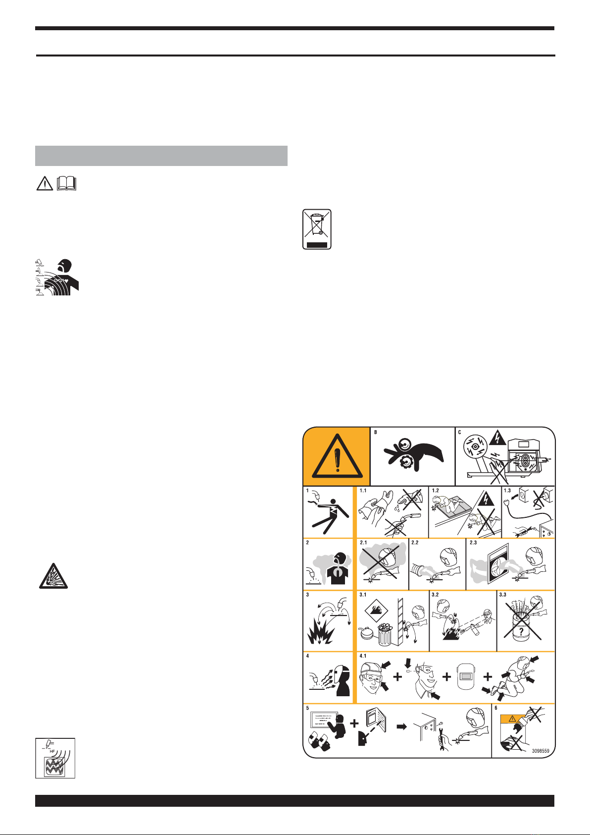
CHIEF MultiMig 721 Multivoltage User manual

1
08/11/2017
33.01013
Inverter
MultiMig 27 1
RS 232
USB
US INSTRUCTION MANUAL FOR WIRE WELDING MACHINE ...................page 2
FR MANUEL D’INSTRUCTIONS POUR POSTE A SOUDER A FIL .............. page 15
ES MANUAL DE INSTRUCCIONES PARA SOLDADORA DE HILO ..............pag. 29
Pag. :45 ÷ 51
Spare parts and electrical schematic
Pièces détachées et schéma électrique
Partes de repuesto y esquema eléctrico

2
INSTRUCTION MANUAL FOR WIRE WELDING MACHINE
IMPORTANT: BEFORE STARTING THE EQUIPMENT,
READ THE CONTENTS OF THIS MANUAL, WHICH
MUST BE STORED IN A PLACE FAMILIAR TO ALL US-
ERS FOR THE ENTIRE OPERATIVE LIFE-SPAN OF THE
MACHINE. THIS EQUIPMENT MUST BE USED SOLELY
FOR WELDING OPERATIONS.
1 SAFETY PRECAUTIONS
WELDING AND ARC CUTTING CAN BE HARM-
FUL TO YOURSELF AND OTHERS. The user
must therefore be educated against the hazards, summa-
rized below, deriving from welding operations. For more
detailed information, order the manual code 3.300.758
ELECTRIC AND MAGNETIC FIELDS - May be dangerous.
•Electric current following through any con-
ductor causes localized Electric and Magnetic
Fields (EMF). Welding/cutting current creates
EMF elds around cables and power sources.
• The magnetic elds created by high currents may affect
the operation of pacemakers. Wearers of vital electronic
equipment (pacemakers) shall consult their physician be-
fore beginning any arc welding, cutting, gouging or spot
welding operations.
• Exposure to EMF elds in welding/cutting may have
other health effects which are now not known.
•All operators should use the followingprocedures in or-
der to minimize exposure to EMF elds from the welding/
cutting circuit:
- Route the electrode and work cables together
- Secure them with tape when possible.
- Never coil the electrode/torch lead around your body.
- Do not place your body between the electrode/torch
lead and work cables. If the electrode/torch lead
cable is on your right side, the work cable should also
be on your right side.
- Connect the work cable to the workpiece as close as
possible to the area being welded/cut.
- Do not work next to welding/cutting power source.
EXPLOSIONS
•Do not weld in the vicinity of containers under
pressure, or in the presence of explosive dust, gas-
es or fumes.
•All cylinders and pressure regulators used in welding op-
erations should be handled with care.
ELECTROMAGNETIC COMPATIBILITY.
This machine is manufactured in compliance with the in-
structions contained in the standard IEC 60974-10 (CL.
A), and must be used solely for professional purposes
in an industrial environment. There may be potential
difculties in ensuring electromagnetic compatibility in
non-industrial environments.
HIGH FREQUENCY
• High frequency (H.F.) can interfere with radio
navigation, safety services, computers, and
communications equipment.
• Have only qualied persons familiar with
electronic equipment perform this installation.
• The user is responsible for having a qualied electrician
promptly correct any interference problem resulting from
the installation.
• If notied by the FCC about interference, stop using the
equipment at once.
• Have the installation regularly checked and maintained.
• Keep high-frequency source doors and panels tight-
ly shut, keep spark gaps at correct setting, and use
grounding and shielding to minimize the possibility of in-
terference.
DISPOSAL OF ELECTRICAL AND ELECTRONIC
EQUIPMENT.
Do not dispose of electrical equipment together
with normal waste!In observance of European Di-
rective 2002/96/EC on Waste Electrical and Electronic
Equipment and its implementation in accordance with
national law, electrical equipment that has reached the
end of its life must be collected separately and returned
to an environmentally compatible recycling facility. As the
owner of the equipment, you should get information on
approved collection systems from our local representa-
tive. By applying this European Directive you will improve
the environment and human health!
IN CASE OF MALFUNCTIONS, REQUEST ASSISTANCE
FROM QUALIFIED PERSONNEL.
1.1 WARNING LABEL

3
The following numbered text corresponds to the label
numbered boxes.
B. Drive rolls can injure ngers.
C. Welding wire and drive parts are at welding voltage dur-
ing operation — keep hands and metal objects away.
1 Electric shock from welding electrode or wiring can kill.
1.1 Wear dry insulating gloves. Do not touch electrode
with bare hand. Do not wear wet or damaged gloves.
1.2 Protect yourself from electric shock by insulating
yourself from work and ground.
1.3 Disconnect input plug or power before working on
machine.
2 Breathing welding fumes can be hazardous to your health.
2.1 Keep your head out of fumes.
2.2 Use forced ventilation or local exhaust to remove fumes.
2.3 Use ventilating fan to remove fumes.
3 Welding sparks can cause explosion or re.
3.1 Keep ammable materials away from welding.
3.2 Welding sparks can cause res. Have a re extinguish-
er nearby and have a watchperson ready to use it.
3.3 Do not weld on drums or any closed containers.
4 Arc rays can burn eyes and injure skin.
4.1 Wear hat and safety glasses. Use ear protection and
button shirt collar. Use welding helmet with correct
shade of lter. Wear complete body protection.
5 Become trained and read the instructions before
working on the machine or welding.
6 Do not remove or paint over (cover) label.
2 GENERAL DESCRIPTIONS
The welding machine is a system suitable for synergic
MIG/MAG and pulsed synergic MIG/MAG welding, devel-
oped with inverter technology.
It is equipped with a 4-roller gearmotor.
This welding machine must not be used to defrost pipes.
2.1 EXPLANATION OF TECHNICAL SPECIFICATIONS
This machine is manufactured according to the following
international standards: IEC 60974-1 / IEC 60974-10 (CL.
A) / IEC 61000-3-11 / IEC 61000-3-12 (see note 2).
No. Serial number. Must be indicated on any re-
quest regarding the welding machine.
3
~
f
1
f
2
Three-phase static transformer-rectier
frequency converter.
MIG Suitable for MIG-MAG welding.
TIG Suitable for TIG welding.
MMA Suitable for MMA welding.
U0. Secondary open-circuit voltage.
X. Duty cycle percentage.
The duty cycle expresses the percentage of
10 minutes during which the welding ma-
chine may run at a certain current without
overheating.
I2. Welding current
U2. Secondary voltage with I2 current
U1. Rated supply voltage.
1~ 50/60Hz Single-phase 50 or 50 Hz power supply.
I1 Max Max. absorbed current at the corresponding
I2 current and U2 voltage.
I1 eff This is the maximum value of the actual cur-
rent absorbed, considering the duty cycle.
This value usually corresponds to the capac-
ity of the fuse (delayed type) to be used as a
protection for the equipment.
IP23S Protection rating for the housing. Grade 3
as the second digit means that this machine
may be stored, but it is not suitable for use
outdoors in the rain, unless it is protected.
SSuitable for use in high-risk environments.
NOTES:
1- The equipment has also been designed for use in envi-
ronments with a pollution rating of 3. (See IEC 60664).
2- This equipment complies with a IEC 61000-3-12
standard provided that the allowed maximum imped-
ance Zmax of the unit is lower or equal to 0.068Wat
the interface point between the user unit and the mains.
The tter or the unit user are responsible for connecting
the unit to a power supply with a maximum allowed
system impedance Zmax lower or equal to 0.068W.
2.2 PROTECTION DEVICES
2.2.1 Bloch protection
In case of welding machine malfunction, the display
screen 1will show the message WARNING to identify the
type of fault. If this message does not disappear when the
machine is switched off and back on, contact the after-
sales service.
2.2.2 Thermal cutout
This appliance is protected by a thermostat which prevents
machine operation whenever acceptable temperatures
are exceeded. In these conditions, the fan continues to
operate and the display screen 1 shows the message
WARNING tH in ashing mode.
2.3.3 Positioning on sloping planes.
Since this welding machine is equipped with wheels
without brake, do not position it on sloping planes, to
prevent machine tilting or uncontrolled movement.
3 CONTROLS LOCATED ON FRONT PANEL.
1 – DISPLAY SCREEN.
This displays both the welding parameters and all the
welding functions.
2 - KNOB
Selects and adjusts both the welding functions and
parameters.
3 – CENTRALIZED COUPLING
To which the welding torch must be connected.
4 – EARTH LEAD OR SOCKET
Where you must connect the earth cable connector.

4
5 – CONNECTOR
DB9 type (RS 232) connector to be used for updating the
welding programs.
Inverter
MultiMig 27 1
RS 232
USB
1
5
2
6
9
7
3
4
8
6 – CONNECTOR
USB-type connector to be used for updating the welding
programs.
7 - FITTING
This is where the gas hose from the TIG torch is to be
connected.
8 – CONNECTOR
This is where the control cable of the Push Pull welding
torch is connected.
9 - SOCKET (+)
Socket where you must connect the earth cable connector
in Tig welding and the electrode clamp in MMA welding.
4 CONTROLS LOCATED ON REAR PANEL.
11 – MIG AND TIG GAS PIPE CONNECTIONS.
12 – SWITCH.
Starts and stops the machine
13 – MAINS CABLE
11
13
12
5 INSTALLATION AND START-UP
• Position the welding machine so as to allow the free
circulation of air inside and, as much as possible, prevent
metal or other dusts from penetrating.
• The machine must be installed by professional personnel.
• All the connections must be performed in compliance
with applicable standards (IEC/CEI EN 60974-9) and with
accident-prevention laws.
• Make sure the power supply voltage corresponds to the
welding machine rating.
• The protection fuses must be sized according to the details
shown on the technical data plate.
• Position the cylinder on the support and x it with the 2
straps; ensure that the straps are secured tightly to the
cylinder to prevent dangerous tilting.

5
• Connect the gas hose to the outlet of the pressure regulator.
• Open the side door.
• Connect the power cord to the socket 4and through
the clamp to the workpiece.
• Connect the earth lead clamp 4to the piece to be welded.
• Fit the wire coil on the support inside the compartment.
The coil must be tted so that the wire unwinds in an
anticlockwise direction.
• Make sure the drive roller is correctly positioned according
to the diameter and type of wire used.
• Cut the welding wire with a well-sharpened tool, keeping
it between your ngers so that it cannot unwind, insert it
inside the pipe exiting from the gear motor and, with the aid
of a nger, insert it inside the steel tube until it comes out of
the adapter.
• Fit the welding torch.
After tting the reel and torch, switch on the machine, select
the suitable synergic curve, following the instructions given
in the service functions (PROCESS PARAMS) paragraph.
Remove the gas nozzle and unscrew the current nozzle
of the torch. Press the torch button until the wire comes
out. BE CAREFUL to keep your face away from the end
lance while the wire is coming out, screw up the current
nozzle and t the gas nozzle.
Open the canister adapter and adjust the gas ow to 8 –
10 l/min.
During welding, the display screen 1displays the actual
work current and voltage. The displayed values may
be slightly different to those set. This can depend on
numerous different factors - type of torch, thickness
different to nominal thickness, distance between current
nozzle and the material being welded, and the welding
speed.
The current and voltage values, at the end of the welding
operation remain stored on the display 1where the word
"HOLD is displayed. To display the set values, the handle
2will have to be moved slightly, while, by pushing the
torch button without welding, the display screen 1shows
the empty voltage value and a current value of 0.
If, while welding the maximum current and voltage values
are exceeded, said values are not stored on the display
and the written "HOLD" is not displayed.
NOTE If 0.6mm diameter wires are used the welding torch
sheath should be replaced with one of suitable internal
diameter. If the internal diameter of the sheath is too big it
does not guarantee smooth wire feeding
6 DESCRIPTION OF THE TOUCH SCREEN 1
DISPLAY FUNCTIONS .
When the machine is
switched on, for a few mo-
ments the display shows: the
article number of the ma-
chine, the serial number, the
Firmware version, the date of
the Firmware development
and the release number of the synergic curves table and the
power supply options.
This information is also given in menu .
6.1 MIG PROCESS. INITIAL DISPLAY.
A
B
C D E F
G
N
O
M L I
A
The screen displays the welding current in Amperes,
the welding voltage in Volts, the suggested thickness
in mm and the welding wire speed in m/min. During weld-
ing the display shows the current and voltage values in a
continuous manner and, once welding is completed, the
last value in Amperes and Volts is displayed along with
the HOLD word.
When the display is in HOLD, BLUE color appears. If If
we press on the center of the display opens a screen that
displays the main parameters of the last welding: the arc
time in seconds switched on, the main current time in
seconds, the average current in amperes, the average
voltage Volt and the total energy in Kj.

6
Ampere and volt parameters are synergically adjusted by
means of knob 2.
BTo carry out the gas test and the wire test se-
lect the corresponding symbol.
When you press the key
(test gas), the gas is released
from the welding torch for a
time period that is adjusted by
means of the key 30 ; the
value is adjusted by means of
the knob 2, from 1 to 60 sec-
onds. To interrupt the gas release press the key again.
When you press the button (wire test), the wire comes
out of the welding torch at a speed that can be adjusted by
means of the key 8.0 ; the speed value, 1 to 22 meters/min-
ute, can be set using the knob 2, and the key must be
pressed for the whole duration of the test.
To return to the previous menu, press the key .
C Start stop.
To choose the welding start mode, 2T, 4T or 3L, select
the corresponding symbol.
Mode 2T.
The machine begins welding when the torch trigger is
pressed, and stops when released. With mode 2T , you
can also choose the parameter HSA (Automatic Hot Start)
and the parameter CRA (Final Crater ller).
The 2 parameters HSA and CRA can be enabled at the
same time, or individually.
Once the parameter HSA has been enabled, the opera-
tor can adjust the Start current from 10 to 200% of the
welding current.
The Current time can also be adjusted from 0.1 to 10
seconds. The Connection time between the Start cur-
rent and the welding current can also be adjusted from 0.1
to 10 seconds. To adjust Start current values, Current
time and Connection time, enter Main Menu by select-
ing the key F MENU and using the key PARAMETERS enter
the process parameters menu. Turn knob 2to select
the parameter, press it to enter the regulation screen and
turn it to adjust the value.
Press that key DEF to reset
the manufacturer set parame-
ters.
After activating the param-
eter CRA, the operator can
adjust the connection time
between the welding current
and the crater lling current (Crater Current) from 0.1 to
10 seconds. The operator can also adjust the crater lling
current from 10 to 200% of the welding current.
The duration of this current can also be adjusted from 0.1 to
10 seconds of the Crater lling time.
To adjust the values of connection time, crater lling cur-
rent and crater lling time enter the main menu by select-
ing key FMENU and enter the process parameters menu.
Turn knob 2to select the parameter, press it to enter the
regulation screen and turn it to adjust the value.
Press the key DEF to reset the
factory set parameters.
Mode 4T.
To begin welding press and release the torch trigger; to
stop welding press and release it again. Together with
mode 4T you may also select function HSA (automatic
hot start) and function CRA (nal crater lling). (See 2T
Mode).

7
Mode 3L.
Specially well suited to weld aluminium. The HSA and
CRA functions are inhibited when mode 3L is activated.
3 currents are available that can be used in welding by
means of the welding torch start key.
The current and the connection time values are set as
follows:
Start Current. Start current, adjustable from 10 to 200%
of set welding current.
Connection Time. Possibility of adjusting from 0.1 to
10 seconds. Denes the connection time between Start
Current and welding current and between welding
current and crater lling current (crater lling at the
welding end)
Crater current may be adjusted from 10 to 200% of set
welding current.
Welding starts at the welding torch key pressure.
The recalled current will be the Start current.
This current is kept as long as the welding torch trigger
is held down; when the welding torch trigger is released
this current connects to the welding current, which is
kept as long as the welding torch trigger is pressed again.
When the torch trigger is pressed again, the welding cur-
rent will connect to the crater lling current and it will be
maintained until the torch trigger is released.
To adjust the values of the Start current, of the connec-
tion time and of the crater lling current enter the Main
Menu with key FMENU and enter the process parame-
ters menu.
Turn knob 2to select the parameter, press it to enter the
regulation screen and turn it to adjust the value.
Press the key DEF to reset the factory set parameters.
D
0.0
Inductance.
The adjustment can vary from -9.9 to +9.9. Zero is the
number set by the factory: if the number is negative, the
impedance decreases and the arc becomes harder; if in-
creased, it becomes softer.
To enter the function select it with your nger. To adjust
the value just turn the knob 2.
E
0.0
Arc Correction.
To modify the arc length select it with your nger. To ad-
just this value just turn the knob 2.
FMENU Menu.
To use this function select it with your nger.
By selecting it you enter the Main Menu.
Process SELECTION OF THE WELDING PROCESS
MIG, TIG OR MMA.
After having selected the MIG , welding process with
knob 2you can select the arc transfer type: MIG Pulse,
MIG Short and MIG Manual.
To conrm the selection press knob 2or the key .
Material SELECTION OF THE WIRE TYPE, DIAME-
TER AND WELDING GAS.
To conrm the selection press knob 2or the key .

8
Parameters PROCESS PARAMETERS SELECTION.
• Arc length correction.
Turn knob 2 to select the parameter and conrm the
selection by pressing the same knob.
The value is adjusted by turning the knob 2.
To conrm the selection press knob 2or the key .
Press the key DEF to reset the factory set parameters.
• Inductance Correction.
Turn knob 2 to select the parameter and conrm the
selection by pressing the same knob.
The value is adjusted by turning the knob 2.
To conrm the selection press knob 2or the key .
Press the key DEF to reset the factory set parameters.
• Torch trigger.
The selection is between Mode 2T, Mode 4T and
Mode 3L.
Turn the knob 2 to select the parameter and conrm
the selection by pressing the knob.
To select the Mode turn knob 2 To conrm the selec-
tion press knob 2or the key .
• Spot.
The selection is between spot time and intermittency.
This function is blocked when function 3L is activated.
When selecting the Spot time on ON, the screen dis-
plays the function Spot time. While selecting it you
can adjust it by means of the adjustment bar.
In addition to the Spot time, the display shows the
Pause time. By selecting this, by means of the ad-
justment bar, it is possible to regulate the pause time
between one welding spot or section and another.
Turn knob 2 to select the parameter and conrm the
selection by pressing the same knob.
The value is adjusted by turning the knob 2. To conrm
the selection press knob 2or the key .
Press the key DEF to reset the factory set parameters.
• HSA, (Automatic Hot Start).
Turn the knob 2 to select the parameter and conrm
the selection by pressing the knob.
When selecting HSA on ON the screen displays the
Start Current, the Current time and the Connection
time. To adjust these parameters see chapter Start
Mode.
Press the key DEF to reset the factory set parameters
• CRA, (nal crater lling).
Turn the knob 2 to select the parameter and conrm
the selection by pressing the knob.
When selecting CRA on ON the screen displays the
Connection time, the Crater lling current and the
Crater lling time. To adjust these parameters see
chapter Start Mode.
Press the key DEF to reset the factory set parameters.
• Soft Start.
Adjustment can vary from 0 to 100%. This is the wire
speed expressed in percentage of the speed set for weld-
ing, before the wire touches the piece to be welded.
This adjustment is important to always obtain good
starts.
The factory adjustment is Auto (Default function)
Turn the knob 2 to select the parameter and conrm
the selection by pressing the knob.
The value is adjusted by turning the knob 2. To conrm
the selection just press the knob 2 or the key .
Press the key DEF to reset the factory set parameters.

9
• Burnback correction.
The adjustment can vary from -9.9 to +9.9. Its purpose
is to adjust the length of the wire coming out of the gas
nozzle after welding. A positive gure corresponds to
greater wire burning.
The factory adjustment is 0 (Default function).
Turn the knob 2 to select the parameter and conrm
the selection by pressing the knob.
The value is adjusted by turning the knob 2. To conrm
the selection just press the knob 2or the key .
Press the key DEF to reset the factory set parameters.
• Double Level.
Active in synergic MIG/MAG processes. This type of
welding varies the current intensity between two lev-
els. Before setting the double level welding, it is neces-
sary to make a short bead to determine the wire speed
and the current to obtain the penetration and the bead
width closest to the type of welding to be made.
In this way the wire feed speed value (and the corre-
sponding current) is determined; the meters per min-
ute that will be set will be alternatively added to and
subtracted from this value.
Before start working you should not forget that for a
correct bead, the minimum overlapping between two
“meshes” must be 50%.
MIN MAX DEF
Frequency 0.1 Hz5.0 Hz1.5 Hz
Speed
difference 0.1 m/min 3.0 m/min 1.0 m/min
Duty cycle 25% 75% 50%
Arc correction -9,9 9,9 0,0
Double level frequency.
The Herz frequency is the number of periods per sec-
ond.
Period means the speed alternating from the higher to
the lower values.
The lower value, that does not penetrate, is used by the
operator to change from one mesh to the next one; the
higher speed, corresponding to the maximum current,
is the penetrating speed and the mesh execution. The
operator will stop to make the mesh.
The speed difference. Is the amplitude of the speed
change in m/min.
The speed change determines the sum and the sub-
traction of m/min from the reference speed described
above. Parameters being the same, when the number
increases the mesh is wider and penetration is deeper.
Duty cycle. The double level time expressed as a per-
centage, is the higher speed/current time as compared
to period duration. Parameters being the same, it de-
termines the mesh diameter and therefore the penetra-
tion.
Arc correction. Sets arc length of the higher speed/
current.
Important: make sure that the arc length is the same
for both currents.
Turn the knob 2 to select the parameter and conrm
the selection by pressing the knob.
The value is adjusted by turning the knob 2. To conrm
the selection simply hold down the knob 2or the key
.
Press the key DEF to reset the factory set parameters.
• Preow.
The adjustment may range from 0 to 10 seconds
Turn the knob 2 to select the parameter and conrm
the selection by pressing the knob.
The value is adjusted by turning the knob 2. To conrm
the selection just press the knob 2or the key .
Press the key DEF to reset the factory set parameters.

10
• Postow.
The adjustment may range from 0 to 25
Turn the knob 2 to select the parameter and conrm
the selection by pressing the knob.
The value is adjusted by turning the knob 2. To conrm
the selection simply hold down the knob 2or the key
.
Press the key DEF to reset the factory set parameters.
Accessories USE OF THE MACHINE ACCESSORIES.
• Bluetooth controlled welding mask. (optional).
In order to use the mask, the kit must be already assem-
bled in the power source. You simply turn on the weld-
ing mask, activate the function on the power source
display, setting to ON and pair via Bluetooth the weld-
ing power source to the mask by selecting the "PAIR"
function. To test the function, simply press the "DARK"
button on the display ensuring that the mask glass be-
comes dark.
• Push-pull torch use instructions.
Adjustment of the Push-pull force can vary from -99
to +99.
This function adjusts the drive torque of the push-pull
motor in order to make the wire feed linear.
Turn the knob 2 to select the parameter and conrm
the selection by pressing the knob.
The value is adjusted by turning the knob 2. To conrm
the selection press knob 2 or the key .
Press the key DEF to reset the factory set parameters.
This function will be displayed on the screen only
after this accessory is assembled inside the power
supply.
• Maximum inching.
The purpose is to stop the welding machine if the wire
ows for the preset length in cm after starting with no pas-
sage of current. Adjustment OFF - 50 cm.
Turn the knob 2 to select the parameter and conrm the
selection by pressing the knob.
To conrm the value, simply hold down the knob 2or the
key .
Press the key DEF to reset the factory set parameters.
Settings MACHINE SETTINGS MENU.
• Date and Time Setting.
Turn the knob 2to select parameter "Clock " and con-
rm the selection by holding down the knob.
Values are adjusted by turning the knob 2and are con-
rmed by holding the knob down.
To conrm date and time press the key OK .
To exit the function press the key .
• Factory setup resetting.
This function allows return to the factory preset values.
Three resetting modes are possible:
- All.
- Resets only stored "job" working programs.
- Excludes the "jobs": Resets all but saves "Job" work-
ing programs.
Turn the knob 2 to select the function and conrm the

11
selection by holding down the knob.
To conrm the value simply hold down the knob 2.
To exit the function press the key .
• Languages. Language selection.
Turn the knob 2 to select the function and conrm the
selection by holding down the knob.
To conrm the language simply hold down knob 2.
To exit the function press the key
• USB Port Function.
This function is activated only when a USB key is
plugged into the connector 6.
Turn the knob 2 to select the function and conrm the
selection by holding down the knob.
To conrm the selection simply hold down knob 2.
To exit the function press the key .
• Use PIN
You can block the use of the PROCESSES, MATERI-
ALS and PARAMETERS using a lock code.
GJOB Job Menu.
In this section you can save, modify, restore, copy or
cancel the working programs.
Saving of a "JOB" program".
After nding the ideal welding condition to be saved,
press the key , the screen displays the rst availa-
ble job number; to conrm the selection press the key
SAVE .
The saved string shows the process, the type and the
diameter of the wire.
Before saving the working program, you may select the
number under which you want to save it by simply turning
the knob 2onto the selected number.
The job screen shows the job knob SAVE and two ad-
ditional buttons COPY and DEL if you press the rst
button you can copy any save any job program and save
it again onto another number while with the "del" button
you can delete any saved job program.
If you press the button JOB you open the screen with
all the saved job programs while by pressing the button
RCL and the button OK you can recall any program
among the saved ones, to modify it.
The button with the selected program number JOB
1is
displayed on the main screen shot ; if you turn the knob
2you may recall one after the other all the saved job pro-
grams in order to modify them.
IAccessory presence - welding mask.
Bluetooth controlled (optional).
LAccessory presence - Push Pull torch
(optional).
MUSB key plugged into the connector 6.
N
Date and Time.
O
Welding program description.
6.2 TIG PROCESS.

12
A
B
C D E F
G
H
O
N M L I
A
The screen displays the welding current in Amperes
and the welding voltage in Volts.
BTo carry out the gas test refer to the relevant
paragraph in "MIG PROCESS".
C Start mode.
Mode 2T and 4T.
For the operation instructions refer to the relevant para-
graphs in "MIG PROCESS".
Mode 3L.
3 currents are available that can be used in welding by
means of the welding torch start key. The current and the
connection time values are set as follows:
Start Current, adjustable from 10 to 200% of set welding
current.
Slope time, possibility of adjusting from 0.1 to 10 seconds.
Denes the connection time between Start current and
welding current and between welding current and crater
lling current or crater lling at the welding end
Start Current, adjustable from 10 to 200% of set welding
current.
Welding starts at the torch trigger pressure. The recalled
current will be the start current. This current is kept as
long as the welding torch trigger is held down; when the
welding torch trigger is released this current connects to
the welding current, which is kept till the welding torch
trigger is pressed again.
When the torch trigger is pressed again, the welding cur-
rent will connect to the Crater lling current and it will
be maintained until the torch trigger is released.
Pulsed (Can be used in Mode 2T-4T and 3L).
Pulsed TIG welding.
In this type of welding, current intensity varies between two
levels; this variation occurs at a given frequency.
Impulse
This item allows the setting of the lower current between
the two currents that are required for this welding pro-
cess; the percentage of this current is displayed related
to the main current.
This impulse can be adjusted from 1% al 100% of the
main current.
Frequency
It is the pulse frequency.
This value can be adjusted from 0.1Hz to 500Hz.
Duty cycle
This is the duration of the highest current, expressed in
percentage, compared to frequency time.
This value can be adjusted from 10% to 90%.
D
0.5s
Current slope down.
Adjustable from 0 to +10 seconds.
E10.0s Post gas.
Adjustable from 0 to +10 seconds.
FMENU Menu.
To enter this function select it with your nger.
Selecting it you enter the Main Menu.
Process SELECTION OF THE WELDING PRO-
CESS, MIG, TIG or MMA (see explanation
under chapter MIG Process).

13
Parameters SELECTION OF PROCESS PARAMETERS
(see explanation under paragraph Start
Mode mode 3L of chapter MIG Process).
Accessories USE OF MACHINE ACCESSORIES (see ex-
planation under chapter MIG Process).
Settings MACHINE SETTINGS MENU (see explana-
tion under chapter MIG Process).
GJOB Job Menu (see explanation under chap-
ter MIG Process).
6.3 MMA PROCESS.
A
B C F
G
H
O
N M L I
A
The screen displays the welding current in Amperes
and the welding voltage in Volts.
BHot Start.
It is the overvoltage supplied at the arc ignition time.
It is adjustable from 0 to 100% of set welding current.
CArc Force.
It is the adjustment of the arc dynamic chara teristic.It is
adjustable from 0 to 100% of set welding current.
FMENU Menu.
To enter this function select it with your nger.
Selecting it you enter the Main Menu.
Process SELECTION OF THE WELDING PRO-
CESS, MIG, TIG or MMA (see explanation
under chapter MIG Process).
Parameters PROCESS PARAMETERS SELECTION.
• Hot Start.
It is the time of overvoltage supplied at the arc ignition
time.
Range from 0 to 100 sec.
Turn the knob 2 to select the parameter and conrm
the selection by pressing the knob.
To adjust the value simply turn the knob 2. To conrm
the selection press knob 2or the key .
Press the key DEF to reset the factory set parameters.
• Hot Start Time.
It is the time of overvoltage supplied at the arc ignition
time.
Range from 0 to 100 sec.
Turn the knob 2 to select the parameter and conrm
the selection by pressing the knob.
To adjust the value simply turn the knob 2. To conrm
the selection press knob 2 or the key .
Press the key DEF to reset the factory set parameters.
• Arc Force.
It is the adjustment of the arc dynamic characteristic.
It is adjustable from 0 to 100% of set welding current.
Turn the knob 2 to select the parameter and conrm
the selection by pressing the knob.
This value is adjusted by turning the knob 2. To conrm
the selection simply hold down the knob 2 or the key
.
Press the key DEF to reset the factory set parameters.

14
Accessories USE OF MACHINE ACCESSORIES (see ex-
planation under chapter MIG Process).
Settings MACHINE SETTINGS MENU (see explana-
tion under chapter MIG Process).
GJOB Job Menu (see explanation under chap-
ter MIG Process).
7 MIG/MAG WELDING
After selecting the process you can select the welding
mode MIG: Pulsed Mig, Mig Short or Mig manual.
For pulsed MIG welding you must select the wire type,
diameter and gas; this selection must be made inside the
Main Menu, by means of keys process and material.
The welding parameters are synergically set by means of
the knob.
In this welding process the ller material is transferred
with an impulsive controlled energy waveform with a re-
sulting constant detachment of melted material drops
that reach the workpiece without splatters. The result is
a melted material welding cord that is transferred to the
workpiece without splatters. The welding cord is thus
well connected with any material type or thickness.
All types of wire, diameter and gas that can be used
are also shown on a plate inside the mobile side panel.
Mig Short.
For MIG short welding you must select the wire type, di-
ameter and gas; this selection must be made inside the
main menu and, by means of keys process and mate-
rial.
The welding parameters are synergically set by means of
the knob.
All types of wire, diameter and gas that can be used
are also shown on a plate inside the mobile side panel.
Mig Manual.
For MIG manual welding you must select the type of wire,
diameter and gas; this selection must be made inside the
Main Menu, and by means of keys process and mate-
rial.
For welding using this process you must adjust the wire
speed and the welding voltage. Pressing the knob on the
main screen you can select the wire speed as well as
welding voltage and value.
All types of wire, diameter and gas that can be used
are also shown on a plate inside the mobile side panel.
8 MMA WELDING
Connect the electrode clamp cable connector to connec-
tor 9and the earth cable clamp to connector 4(observing
the polarity stated by the electrode manufacturer).
In order to prepare the machine for MMA welding, follow
the instructions previously described in the menu.
9 TIG WELDING
Connect the earth cable to the positive pole 9 and the
torch to the negative connector 4.
Connect the gas hose to the socket 7.
In order to prepare the machine for TIG welding, follow
the instructions previously described in the menu.
10 MAINTENANCE
All maintenance jobs must be performed by
professional personnel according to the CEI 26-29
(IEC 60974-4) standard.
10.1 GENERATOR MAINTENANCE
In case of maintenance inside the appliance, make sure
the switch 12 is in “O” position and that the power supply
cable is disconnected from the mains.
Periodically, also clean the inside of the appliance and
remove any metal dust using compressed air.
10.2 HOW TO PROCEED AFTER MAKING REPAIRS.
After making repairs, always ensure the wires are fully
insulated between the primary side and the secondary
side of the machine. Avoid the wires coming into contact
with moving parts or parts that heat up during operation.
Fit all the clamps back as on the original machine so as to
avoid any contact between the primary and secondary in
case of accidental lead breakage or disconnection.
Also t the screws back on with the toothed washers as
on the original machine.

15
MANUEL D’INSTRUCTIONS POUR POSTE A SOUDER A FIL
IMPORTANT: AVANT LA MISE EN MARCHE DE LA MA-
CHINE, LIRE CE MANUEL ET LE GARDER, PENDANT
TOUTE LA VIE OPÉRATIONNELLE, DANS UN ENDROIT
CONNU PAR LES DIFFÉRENTES PERSONNES INTÉ-
RESSÉES. CETTE MACHINE NE DOIT ÊTRE UTILISÉE
QUE POUR DES OPÉRATIONS DE SOUDURE.
1 PRÉCAUTIONS DE SÉCURITÉ
LA SOUDURE ET LE DÉCOUPAGE À L’ARC
PEUVENT ÊTRE NUISIBLES À VOUS ET AUX
AUTRES. L’utilisateur doit pourtant connaître les risques,
résumés ci-dessous, liés aux opérations de soudure.
Pour des informations plus détaillées, demander le ma-
nuel code.3.300758
BRUIT
Cette machine ne produit pas elle-même des bruits
supérieurs à 80 dB. Le procédé de découpage au
plasma/soudure peut produire des niveaux de bruit
supérieurs à cette limite; les utilisateurs devront donc mette
en oeuvre les précautions prévues par la loi.
CHAMPS ELECTROMAGNETIQUES- Peuvent être dan-
gereux.
· Le courant électrique traversant n’importe
quel conducteur produit des champs élec-
tromagnétiques (EMF). Le courant de sou-
dure ou de découpe produisent des champs
électromagnétiques autour des câbles ou
des générateurs.
• Les champs magnétiques provoqués par des courants
élevés peuvent interférer avec le fonctionnement des sti-
mulateurs cardiaques.
C’est pourquoi, avant de s’approcher des opérations de
soudage à l’arc, découpe, décriquage ou soudage par
points, les porteurs d’appareils électroniques vitaux (sti-
mulateurs cardiaques) doivent consulter leur médecin.
• L’ exposition aux champs électromagnétiques de sou-
dure ou de découpe peut produire des effets inconnus
sur la santé.
Pour reduire les risques provoqués par l’exposition aux
champs électromagnétiques chaque opérateur doit
suivre les procédures suivantes:
- Vérier que le câble de masse et de la pince porte-
électrode ou de la torche restent disposés côte à côte.
Si possible, il faut les xer ensemble avec du ruban.
- Ne pas enrouler les câbles de masse et de la pince
porte-électrode ou de la torche autour du corps.
- Ne jamais rester entre le câble de masse et le câble de
la pince porte-électrode ou de la torche. Si le câble de
masse se trouve à droite de l’opérateur, le câble de la
pince porte-électrode ou de la torche doit être égale
ment à droite.
- Connecter le câble de masse à la pièce à usiner aussi
proche que possible de la zone de soudure ou de dé-
coupe.
- Ne pas travailler près du générateur.
EXPLOSIONS
· Ne pas souder à proximité de récipients sous
pression ou en présence de poussières, gaz ou
vapeurs explosifs. Manier avec soin les bouteilles et les
détendeurs de pression utilisés dans les opérations de
soudure.
COMPATIBILITE ELECTROMAGNETIQUE
Cette machine est construite en conformité aux indica-
tions contenues dans la norme harmonisée IEC 60974-
10(Cl. A) et ne doit être utilisée que pour des buts profes-
sionnels dans un milieu industriel. En fait, il peut y avoir
des difcultés potentielles dans l’assurance de la com-
patibilité électromagnétique dans un milieu différent de
celui industriel.
HAUTE FRÉQUENCE (H.F.)
• La haute fréquence (HF) peut interférer
avec la radionavigation, les services de
sécurité, les ordinateurs, et en général
avec les équipements de communication
• Faites faire l’installation uniquement par
des personnes qualiées qui sont familiarisés avec les
équipements électroniques.
• L’utilisateur nal a la responsabilité de recourir à un
électricien qualié qui saura résoudre rapidement tout
problème d’interférence résultant de l’installation
• Si la FCC signale des interférences, arrêtez immédiate-
ment d’utiliser l’équipement
• L’équipement doit être régulièrement entretenu et
contrôlé
• Le générateur haute fréquence doit rester fermé, et les
électrodes doivent être maintenues à la bonne distance
de l’éclateur à étincelle
ÉLIMINATION D’ÉQUIPEMENTS ÉLECTRIQUES
ET ÉLECTRONIQUES
Ne pas éliminer les déchets d’équipements
électriques et électroniques avec les ordures
ménagères!Conformément à la Directive Européenne
2002/96/CE sur les déchets d’équipements électriques
et électroniques et à son introduction dans le cadre des
législations nationales, une fois leur cycle de vie terminé,
les équipements électriques et électroniques doivent
être collectés séparément et conférés à une usine de
recyclage. Nous recommandons aux propriétaires des
équipements de s’informer auprès de notre représentant
local au sujet des systèmes de collecte agréés.En vous
conformant à cette Directive Européenne, vous contri-
buez à la protection de l’environnement et de la santé!
EN CAS DE MAUVAIS FONCTIONNEMENT, DEMANDER
L’ASSISTANCE DE PERSONNEL QUALIFIÉ.
1.1 PLAQUETTE DES AVERTISSEMENTS
Le texte numéroté suivant correspond aux cases numé-
rotées de la plaquette.
B. Les galets entraînement l peuvent blesser les mains.
C. Le l de soudure et le groupe entraînement l sont
sous tension pendant le soudage. Ne pas approcher
les mains ni des objets métalliques.
1. Les décharges électriques provoquées par l’élec-
trode le câble peuvent être mortelles. Se protéger de
manière adéquate contre les décharges électriques.

16
1.1 Porter des gants isolants. Ne pas toucher l’électrode
avec les mains nues. Ne jamais porter des gants hu-
mides ou endommagés.
1.2 S’assurer d’être isolés de la pièce à souder et du sol
1.3 Débrancher la che du cordon d’alimentation avant
de travailler sur la machine.
2. L’inhalation des exhalations produites par la soudure
peut être nuisible pour la santé.
2.1 Tenir la tête à l’écart des exhalations.
2.2 Utiliser un système de ventilation forcée ou de dé-
chargement des locaux pour éliminer toute exhalai-
son.
2.3 Utiliser un ventilateur d’aspiration pour éliminer les
exhalations.
3. Les étincelles provoquées par la soudure peuvent
causer des explosions ou des incendies.
3.1 Tenir les matières inammables à l’écart de la zone
de soudure.
3.2 Les étincelles provoquées par la soudure peuvent
causer des incendies. Maintenir un extincteur à proxi-
mité et faire en sorte qu’une personne soit toujours
prête à l’utiliser.
3.3 Ne jamais souder des récipients fermés.
4. Les rayons de l’arc peuvent irriter les yeux et brûler la
peau.
4.1 Porter un casque et des lunettes de sécurité. Utili-
ser des dispositifs de protection adéquats pour les
oreilles et des blouses avec col boutonné. Utiliser des
masques et casques de soudeur avec ltres de de-
gré approprié. Porter des équipements de protection
complets pour le corps.
5. Lire la notice d’instruction avant d’utiliser la machine
ou avant d’effectuer toute opération.
6. Ne pas enlever ni couvrir les étiquettes d’avertissement.
2 DESCRIPTIONS GENERALES
Le poste à souder est un poste approprié pour le soudage
MIG/MAG synergique et MIG/MAG pulsé synergique,
réalisé avec la technologie inverter.
Le poste à souder est équipé de motoréducteur à 4
rouleaux.
Ce poste à souder ne doit pas être utilisé pour décongeler
des tuyaux.
2.1 EXPLICATION DES DONNÉES TECHNIQUES
La machine est fabriquée d’après les normes suivantes :
IEC 60974-1 / IEC 60974-10 (Cl. A) / IEC 61000-3-11/ IEC
61000-3-12 (voir remarque 2).
N°. Numéro de matricule à citer toujours pour
toute question concernant le poste à souder.
3
~
f
1
f
2
Convertisseur statique de fréquence
triphasé transformateur-redresseur
trasformatore raddrizzatore.
MIG Indiqué pour soudage MIG-MAG.
TIG Indiqué pour soudage TIG.
MMA Indiqué pour soudage MMA.
U0. Tension à vide secondaire.
X. Facteur de service en pourcentage.
Lefacteurdeserviceindique,enpourcentage
sur 10 minutes, pendant combien de temps
le poste peut souder avec un courant
déterminé sans surchauffer.
I2. Courant de soudure
U2. Tension secondaire avec courant I2
U1. Tension nominale d’alimentation.
1 ~ 50/60Hz Alimentation monophasée 50- ou 60-Hz.
I1 Max Courant max. absorbé au courant
correspondant I2 et tension U2.
I1 eff C’est la valeur maximale du courant effectif
absorbé compte tenu du facteur de service.
Généralement, cette valeur correspond à la
capacité du fusible (type retardé) à utiliser
comme protection de la machine.
IP23S Degré de protection de la carcasse. Degré
3 en tant que deuxième chiffre signie que
cette machine peut être entreposée, mais
elle ne peut pas être utilisée à l’extérieur en
cas de précipitations, à moins qu’elle n’en
soit protégée.
SAppropriée pour un usage à haut risque
milieux.
REMARQUES :
1- En outre, la machine est indiquée pour opérer dans
des milieux avec degré de pollution 3. (Voir IEC 60664).
2- Cette machine est conforme à la norme IEC 61000-3-12
à condition que l’impédance maximale Zmax admise
de l’installation soit inférieure ou égale à 0.93 dans le
point d’interface entre l’installation de l’utilisateur et le
réseau publique. Il revient à l’installateur ou à l’utilisateur
de la machine de garantir, après avoir éventuellement
consulté l’opérateur du réseau de distribution, que la

17
machine soit reliée à une alimentation avec impédance
maximale de système admise Zmax inférieure ou égale
à 0.93.
2.3 PROTECTIONS
2.3.1 Protection de verrouillage
En cas de dysfonctionnement du poste à souder, l'écran
1 peut afcher un message D'ALERTE identiant le type
de défaut; si, en éteignant et en rallumant la machine, le
message persiste, contacter le service d'assistance.
2.3.2 Protection thermique
Cette machine est protégée par un thermostat empêchant
le fonctionnement de la machine en cas de dépassement
des températures admises. Dans ces conditions, le
ventilateur continue de fonctionner et l'écran A afche le
sigle D'ALERTE tH clignotant.
2.3.3 Positionnement des plans inclinés.
Cette machine étant munie de roues sans
freins, il faut faire attention à ne pas la positionner sur
des surfaces inclinées pour éviter tout renversement ou
mouvement non contrôlé.
3 COMMANDES SUR LE PANNEAU AVANT
Inverter
MultiMig 27 1
RS 232
USB
1
5
2
6
9
7
3
4
8
1 - ÉCRAN.
Il afche aussi bien les paramètres de soudage que
toutes les fonctions de soudage.
2 - BOUTON
Par ce bouton, on sélectionne et règle aussi bien les
fonctions que les paramètres de soudage.
3 – RACCORD CENTRALISE
Où il faut brancher la torche de soudure.
4 - CABLE DE MASSE OU PRISE
Prise où il faut brancher le connecteur du câble de masse.
5 – CONNECTEUR
Connecteur type DB9 ( RS 232) à utiliser pour mettre à
jour les programmes de soudure.
6 – CONNECTEUR
Connecteur type USB à utiliser pour mettre au jour les
programmes de soudure.
7 – RACCORD
Où il faut brancher le tuyau du gaz sortant de la torche
TIG.
8 – CONNECTEUR
On y relie le câble de commande de la torche Push Pull.
9 - PRISE (+)
Prise où il faut brancher le connecteur du câble de
masse en soudage Tig, la pince porte-électrode en
soudage MMA.
4 COMMANDES SUR PANNEAU ARRIÈRE.
11
13
12
11- RACCORDS TUYAU DE GAZ MIG ET TIG.
12 - INTERRUPTEUR.
Il met en marche et arrête la machine
13 - CABLE DE SECTEUR.

18
5 MISE EN PLACE ET ASSEMBLAGE
Positionner le poste à souder de façon à permettre une
libre circulation de l'air à l'intérieur et éviter l'introduction
de poudres de métal ou de tout autre type.
• L'assemblage de cette machine doit être faite par du
personnel quali é.
• Tous les branchements doivent être exécutés
conformément aux normes en vigueur (IEC/CEI EN
60974-9), et dans le respect total des lois en matière
de prévention des accidents.
• Véri er que la tension d’alimentation correspond bien à
la tension nominale du poste à souder.
• Dimensionner les fusibles de protection d'après les données
indiquées sur la plaquette des données techniques.
• Positionner la bouteille sur le support, et utiliser les deux
ceintures pour la bloquer. Les ceintures doivent être
parfaitement adhérentes à la bouteille pour éviter tout
possible renversement.
• Relier le tuyau gaz à la sortie du détenteur de pression.
• Ouvrir la porte latérale.
• Connecter le câble de masse 4et la borne sur la pièce
à souder.
• Monter la bobine du l sur le support à l'intérieur
du compartiment. La bobine doit être montée sur le
support de façon à ce que le l se déroule dans le sens
contraire des aiguilles d'une montre.
• Contrôler que le rouleau d'entraînement est bien
positionné en fonction du diamètre et du type de l
utilisé.
• Couper le l avec un outil bien aiguisé, en maintenant le
l entre les doigts, de façon à ce qu'il ne puisse pas se
dérouler, l'en ler à l'intérieur du petit tuyau qui sort du
motoréducteur et à l'aide d'un doigt, l'en ler également
à l'intérieur de la cannette en acier de l'adaptateur,
jusqu'à ce qu'il ressorte par l'adaptateur.
• Monter la torche de soudure.
Après avoir monter la bobine et la torche, mettre en
marche la machine, choisir la courbe synergique adaptée,
en suivant les instructions décrites dans le paragraphe «
fonctions de service » (PROCESS PARAMS). Retirer la
buse gaz et dévisser le buse porte-courant de la torche.
Appuyer sur le bouton de la torche jusqu'à ce que le l
sorte, ATTENTION ! Éloigner le visage de la lance
terminale quand le l sort; visser la buse porte-courant
et en ler la buse gaz.
Ouvrir le réducteur de la bombonne et régler le débit du
gaz à 8/10 l/min.
Pendant le soudage, l'écran 1 af che le courant et la
tension effective de travail. Les valeurs visualisées
peuvent être légèrement différentes des valeurs de
réglage ; ceci peut dépendre de beaucoup de facteurs:
types de torche, épaisseur différente de l'épaisseur
nominale, distance entre la buse porte courant et le
matériel à souder et la vitesse de soudage.
Les valeurs de courant et tension, à la n du soudage
sont mémorisés sur l' af cheur 1où apparaît l'inscription
"HOLD; pour visualiser les valeurs réglées, il faut bouger
légèrement le bouton 2, tandis qu'en appuyant sur la
gâchette de la torche sans souder, sur l'écran 1 s ' a f c h e
la valeur de tension à vide et la valeur de courant égale
à 0.
Si pendant la soudure les valeurs maximales de courant
et de tension sont dépassées, elles ne restent pas mé-
morisées sur l'af cheur et l'inscription "HOLD" n'est pas
a f c h é e .
N.B. Si on utilise des ls de 0,6mm de diamètre il est
conseillé de remplacer la gaine de la torche de soudure
avec una gaine de diamètre interne approprié.
Une gaine avec un diamètre interne trop grand n'assure
pas un déroulement correct du l de soudure.
6 DESCRIPTION DES FONCTIONS DE L' AFFI-
CHEUR TOUCH SCREEN 1.
À l'amorçage de la machine,
l'af cheur visualise pendant
quelques instants: Le numéro
d' article de la machine, le
numéro de matricule, la ver-
sion du Micrologiciel, la date
de développement du Micro-
logiciel, le numéro de release du tableau des courbes syner-
giques et les options liées au générateur. Cette information
est incluse également à l'intérieur du menu .

19
6.1 PROCESSUS MIG. PAGE ECRAN INITIAL.
A
B
C D E F
G
N
O
M L I
A
L' afcheur visualise le courant de soudure en Ampère,
la tension de soudure en Volt, l'épaisseur suggéré en
mm et la vitesse du l de soudure in m/min. Pendant le
soudage l' afcheur signale de façon continue les valeurs
de courant et tension, et la n du soudage signale la der-
nière valeur en Ampère et Volt et apparaît l'inscription
HOLD. Lorsque l'écran afche les paramètres en HOLD,
ils sont en bleu. Lorsque nous sommes en HOLD si nous
pressons sur le centre de l'écran, ouvre un écran qui af-
che les principaux paramètres de la dernière soudure: le
temps d'arc en quelques secondes sous tension, la prin-
cipale heure en secondes, le courant moyen en ampères,
la tension moyenne Volt et l'énergie totale en kJ.
Les paramètres en ampère et volt sont réglés, de façon
synergique, au moyen du bouton 2.
BPour exécuter le test gaz et le test du l sélec-
tionner le symbole correspondant.
Quand on appuie sur la tou-
che (test gaz) le gaz sort
de la torche pendant un délai
qui est réglé au moyen de la
touche 30 et la valeur est
réglée , au moyen du bouton
2, de 1 à 60 secondes. Pour
interrompre la sortie du gaz appuyer de nouveau sur la tou-
che .
Quand on appuie sur la touche (test l) le l sort de
la torche à une vitesse qui est réglée en sélectionnant la
il touche 8.0 et la valeur est réglée au moyen du bouton
2, de 1 à 22 mètres/minute, la touche doit être main-
tenue appuyée pendant toute la durée du test.
Pour revenir au menu précédent, appuyer touche .
C Start mode.
Pour choisir le mode de démarrage soudage 2T, 4T ou 3L
sélectionner le symbole correspondant.
Mode 2T.
La machine commence à souder quand on appuie sur la
touche de la torche et s'arrête quand on la relâche. Avec
le mode 2T on peut sélectionner également le paramètre
HSA (Hot Start Automatique) et le paramètre CRA (Rem-
plissage du Cratère Final).
Les 2 paramètres HSA e CRA peuvent être activés tous
les deux en même temps, ou séparément.
La fonction HSA étant activée, l'opérateur pourra régler
le niveau du Courant de démarrage (Start Curr) de 10 à
200% du courant de soudure.
Pourra être réglé le Temps de courant de soudure de
0,1 à 10 secondes. Pourra être réglé également le Temps
de raccord entre le courant de démarrage et le courant
de soudure de 0,1 à 10 secondes.
Pour régler les valeurs du Courant de démarrage, de
Temps de courant et du Temps de raccord il faut en-
trer dans le menu principal en sélectionnant la touche F
MENU et au moyen de la touche Paramètres entrer dans
le menu, paramètres de processus. Tourner le bouton 2
pour sélectionner le paramètre; si on appuie sur la touche
on entre dans la page écran de réglage et la valeur est
réglée en tournant le bouton.
Appuyer sur la touche DEF
pour rétablir les paramètres
préréglée par le fabricant.
Après avoir activé la fonction
CRA, l'opérateur pourra
régler le temps de raccord
entre le courant de soudure et le courant de remplissa-
ge du cratère de 0,1 à 10 secondes.
Pourra régler le courant de remplissage du cratère de
10 à 200% du courant de soudure.
Pourra régler la durée du courant de 0,1 à 10 secondes
du temps de cratère.
Pour régler les valeurs du Temps de raccord, du Cou-
rant de cratère et du Temps de cratère il faut entrer
dans le menu principal en sélectionnant la touche F
MENU et au moyen de la touche Paramètres entrer dans
le menu, paramètres de processus.
Tourner le bouton 2pour sélectionner le paramètre; si
on appuie sur la touche on entre dans la page écran de

20
réglage et la valeur est réglée en tournant le bouton.
Appuyer sur la touche DEF
pour rétablir les paramètres
préréglée par le fabricant.
Mode 4T.
Pour commencer le soudage, appuyer et relâcher le bou-
ton torche, pour interrompre il faut appuyer et relâcher le
bouton encore une fois. Avec le mode 4T on peut sélec-
tionner également la fonction HSA (hot marche automa-
tique) et la fonction CRA (remplissage du cratère nal).
(Voir Mode 2T).
Mode 3L.
Particulièrement indiqué pour souder l'aluminium. Les
fonctions de HSA et CRA sont inhibées quand le mode
3L est activé. Au moyen du bouton de la torche sont di-
sponibles 3 courants rappelables en soudure.
L'enregistrement des courants et du temps de raccord
est le suivant:
Courant initial. Possibilité de réglage de 10 à 200% du
courant enregistré de soudure.
Temps de raccord. Possibilité de réglage de 0,1 à 10
secondes. Dénit le temps de raccord entre le courant
de démarrage et le courant de soudure et entre le cou-
rant de soudure et le courant de cratère (remplissage).
Le courant de cratère, peut être réglé de r 10 à 200% du
courant enregistré de soudure.
La soudure commence quand le bouton torche est en-
foncé.
Le courant rappelé sera le courant de démarrage.
Ce courant est maintenu jusqu'à quand le bouton torche
est enfoncé; quand le bouton est relâché, le courant de
démarrage se raccorde au courant de soudure et il est
maintenu jusqu'à quand le bouton torche est de nouveau
enfoncé. Quand le bouton torche est enfoncé encore, le
courant de soudure se raccorde au courant de crater-
ller et il est maintenu jusqu'à quand le bouton torche est
relâché. Pour régler les valeurs du courant de démar-
rage, du temps de raccord et du courant de cratère
il faut entrer dans le menu principal en sélectionnant la
touche FMENU et au moyen de la touche PARAMÈTRES
entrer dînas le menu, paramètres de processus.
Tourner le bouton 2pour sélectionner le paramètre; si
on appuie sur la touche on entre dans la page écran de
réglage et la valeur est réglée en tournant le bouton.
Appuyer sur la touche DEF pour rétablir les paramètres
préréglée par le fabricant.
D
0.0
Inductance.
Le réglage peut varier de -9,9 à +9,9. Zéro est la valeur
enregistrée par le fabricant; si le numéro est négatif
l'impédance diminue et l'arc devient plus dur tandis que
si l'impédance augmente l'arc est plus doux.
Pour avoir accès à la fonction il suft de la sélectionner
avec un doigt. Pour régler la valeur il suft de tourner le
bouton 2.
E
0.0
Correction de l'arc.
Pour modier la longueur d’arc il suft de la sélectionner
avec un doigt. Pour régler la valeur il suft de tourner le
bouton 2.
Table of contents
Languages:
Other CHIEF Welding System manuals

CHIEF
CHIEF MULTICUTTER MC40 User manual

CHIEF
CHIEF Electron MultiSpot M25 AL User manual

CHIEF
CHIEF M30 User manual

CHIEF
CHIEF MultiMig 521 User manual

CHIEF
CHIEF Multi-Spot M22AL User manual

CHIEF
CHIEF MIG 240 208/240 V User manual

CHIEF
CHIEF Elektron MultiMig 621 User manual

CHIEF
CHIEF MultiMig 511 User manual

CHIEF
CHIEF MI300T User manual

CHIEF
CHIEF M30 Pro ALU User manual
Popular Welding System manuals by other brands

iWeld
iWeld CUT 50 IGBT user manual

Sherman
Sherman MIG 230/2 user manual

Power first
Power first SMART TIG AC/DC-200P user manual

Leister
Leister VARIMAT V2 Series operating instructions

Air Liquide
Air Liquide SAF-FRO DIGIWAVE II Instruction for operation and maintenance

MK Products
MK Products 248-8XX owner's manual