chinesport INFRA LAMP 750 Operating instructions
Rev. 01 of 08/08/2013_CP Page 1 of 15
Item code: EL0157
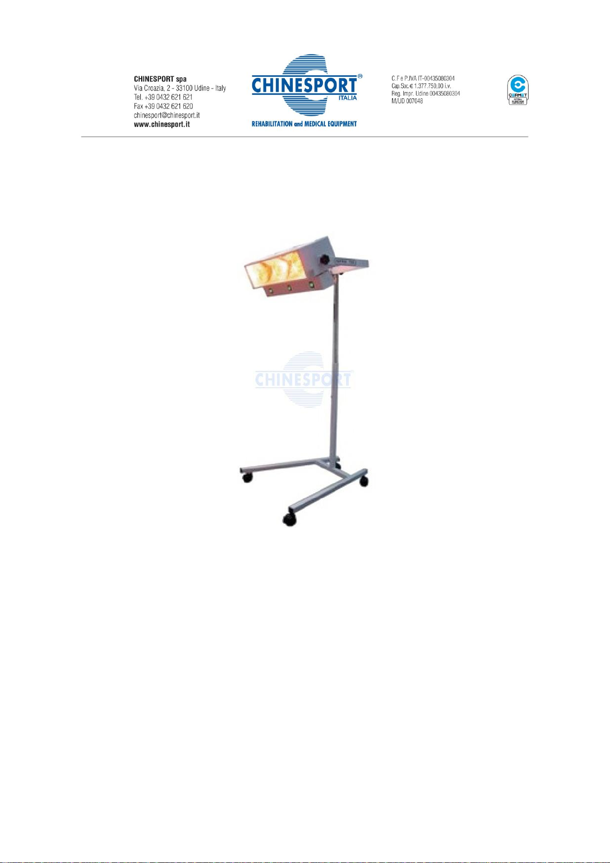
INFRA LAMP 750
Infrared therapy floor lamp
User and Maintenance Manual
Rev. 01 of 08/08/2013_CP Page 2 of 15
Table of Contents
1. CLASSIFICATION………………………………………………………………………………………………03
2. INTENDED USE…………………………………………………………………………………………………03
3. TECHNICAL DATA………………….………………………………………………………………………..03
4. ASSEMBLING……………………………………………………………………………………………………04
5. REQUIREMENTS FOR THE USER……………………………………………………………………....05
6. USE OF EYE PROTECTION………………………….……………………………………………………..06
7. IGNITION……………………………………….…………………………………………………………………06
8. NOTICES FOR TRANSPORT AND STORAGE……………………………………………………..08
9. MEAN OF THE LABELLING SYMBOLS………………………………………………………………09
10. SERIAL NUMBER CODIFICATION……………………………………………………………………..09
11. DIRECTIONS FOR USE AND NOTICES………………………………………..…………………….09
12. MAINTENANCE……………………………………..…………………………………………………….......11
13. BREAKDOWNS AND REPAIR….………………………….……………………………………………..12
14. USEFUL LIFE OF THE DEVICE ……………………………….…………………………………………..14
15. ENCLOSED ACCESSORIES………………………………………………………………………………..14
16. SPARE PARTS…………………………………………………………………………………………………...14
Follow us on

Rev. 01 of 08/08/2013_CP Page 3 of 15
CLASSIFICATION
According to Standard EN60601- 1 : CLASS I TYPE B;
According to Directive CEE 93/42 : CLASS II a;
IP Protection: : IP 20
WARNING
THIS DEVICE IS NOT SUITABLE TO BE USED IN PRESENCE OF ANESTETIC AIR/OXIGEN
FLAMMABLE SUBSTANCE
INTENDED USE
Use in orthopedic field: treatment of arthritis, lumbago, rheumatisms, sprains, and generally where a
penetrating heat source is needed.
Use in physiotherapic field: massage preparation and body heating for a better absorbation of creams by
the skin;
Heating: in cold rooms it's possible to obtain an immediate heating for the irradiate person;
WARNING
BEFORE USING THIS MEDICAL DEVICE IT’S NECESSARY TO READ THIS MANUAL THAT MUST
REMAIN AVAILABLE NEAR THE DEVICE FOR CONSULTATION BY THE OPERATOR;
EXPOSURE TO INFRARED RAYS HAS CONTROINDICATIONS AND SIDE EFFECTS: FOR USE FOLLOW
CAREFULLY THE MEDICAL PRESCRIPTIONS
TECHNICAL DATA
MECHANICAL DATA
Net weight : Kg 14
Dimension of the equipment : cm 55x15x23
Regulating height : from cm 82 to cm 152
ELECTRICAL DATA
• Voltage : 230 V 50 Hz
• Power : 750 W
• Fuses : 6,3A
• This device isn’t subjected to electromagnetic interferences
• Basic network insulation provided by bipolar temporized switch

Rev. 01 of 08/08/2013_CP Page 4 of 15
IR IRRADIANCE
The model Infra 750 is equipped with three lamps whose filament reaches the colour temperature of 2450
K.
The infrared irradiance peak is in correspondence to the wave lenght of 1200 nm.
INFRARED IRRADIATION INTENSITY OF ONE SINGLE LAMP OF 250W:
- at 20 cm: 340 mW/cm2
- at 30 cm: 170 mW/cm2
- at 40 cm: 100 mW/cm2
- at 50 cm: 70 mW/cm2
The tolerance on these values is ± 20%
COMPOSITION OF THE METALLIC PARTS
• LAMP BODY : electrostatic painted iron
• TUBES : chromated / electrostatic painted iron
• WHEELS OF BASE : plastic
ASSEMBLING
Insert the end with two holes of the white painted tube in the transverse tube of the base (be careful that
the hole of at the top of the white tube is in back position) tightening the two screws (after inserting insert
the toothed washer “A” and smooth wather “B” to the two bolts through the holes of tube and base.
Tight strongly with a spanner.
Insert the side with stop of the chromated tube into the top end of the painted tube until its stop, so that
the two holes are lined up. String the plated washer into the hexagonal head 8MA bolt (Group "B"), insert
the bolt with the washer into the two lined up holes and screw it strong with a spanner.
Turn out the cut head 3MA screw of the top end of the chromated tube.
Screw off the knob back of the lamp-hold fork and insert the fork into the chromated tube.
Stop the fork on the tube at the wanted height by screwing the back knob. Turn the cut head screw in
again.
Insert the metallic washer between the knob and the fork hole and the black rubber washer between fork
and lamp hole. Screw the two knobs strongly to fix the body of the lamp.
Apply the black handle at the top of the device fixing it with the screws after inserting the toothed washer
“C” and smooth washer “D” .
Rev. 01 of 08/08/2013_CP Page 5 of 15
ASSEMBING OF IR EMITTERS
WARNING
DURING THIS OPERATION THE DEVICE MUST BE DISCONNECTED FROM NETWORK VOLTAGE.
1. Unscrew the two lateral screws of the protection grid;
2. Extract the grid from the left side;
3. Unpack the three IR emitters and screw them on their lamp-sockets;
4. Apply the two black protection on the two ends of the grid and insert the grid into the device;
5. Apply the protection plaque of the grid with the two screws;
At the end of the assembling check what follows :
1. Check tightening of the assembled parts, check if the lamps are well fixed to the fork and that the two
knobs and upper handle are tighted;
2. Check operation of the green warning light: insert the power supply cord plug into a 10A 230V 50Hz
socket and check the lighting of the 230V LINE green warning light;
3. Lighting test:
3.1 –Place on “I” position the three “on/off” switches and load both timers on 15’;
3.2 –Check the lighting of all three IR lamps and the three green lights of the three switches;
3.3 –Check the switching off of the lamps after 15’ when at least one timer is zeroed;
WARNING
DON’T USE THE DEVICE IF ONE OR MORE EMITTERS ARE BROKEN OR MISSED AND/OR THE
PROTECTIVE GRID HAS BEEN REMOVED AND/OR TIMERS ARE BROKEN
Operators that carry out these tests, use the device or are in the environment during lighting must wear
proper goggles.
REQUIREMENTS FOR THE USER
This device can be used only by persons who know operation and hazards associated with the use
and have the following requirements:
Identification Professional user : Doctor or Nurse
a) Age min. 18 years / max 80 years;
b) Education minimum 8 years of schooling but no pre-requisite of specific knowledge;
d) Language Italian or English.
Rev. 01 of 08/08/2013_CP Page 6 of 15
The operator must be aware of:
- Instructions and warnings contained in the user manual;
- Time, distance and frequency of sessions prescribed by the doctor to the patient.
ATTENTION
This device cannot be used by people with disabilities in particular blind subjects.
The operator must have attention to the following aspects:
- Use eye protection;
- Duration of the session;
- Maintaining the patient’s position with respect to the device;
- No other people in the room;
USE OF EYE PROTECTION
This device is equipped with IR goggles (EN 166/171 and Dir. 89/686/CEE Standards) which must be always
worn by operators during the lighting against directed or reflected IR radiations.
ATTENTION
Replace these protections in case of breakage.
Clean before every use with neutral a diluited sterilizing product.
The materials used in these eye protections may cause allergic reactions to sensible persons.
IT’S NECESSARY TO USE EYE PROTECTIONS ACCORDING THE ABOVE MENTIONNED STANDARDS.
IGNITION
Before lighting read these important warnings :
WARNINGS
THIS MEDICAL DEVICE MUST BE USED ONLY BY MEDICAL OR PARA-MEDICAL OPERATORS
WHO HAVE READ THIS MANUAL AND FOLLOW THE INSTRUCTIONS EXACTLY.
READ CAREFULLY THE WARNINGS CONTAINED IN THE IR SAFETY CARD ATTACHED TO THIS
MANUAL.
THE DEVICE MUST BE PLACED ON A FLAT AND SMOOTH SURFACE, WITH ALL FOUR WHEEL
BRAKES BLOCKED.
BEFORE LIGHTING THE DEVICE BE CAREFUL THAT THE HELMET AND THE FEEDER BOX
AREN’T COVERED BY ANY OBJECTS (CLOTHES, PAPERS,…) AND THERE IS NO PRESENCE OF
FLAMMABLES GAS AND SUBSTANCES. DON’T USE IN PRESENCE OF ANAHESTETIC GAS OR
HIGH LEVEL OF OXIGEN.

Rev. 01 of 08/08/2013_CP Page 7 of 15
WARNINGS
PLACE THE DEVICE AT LEAST AT ONE METER OF DISTANCE FROM THE WALLS OF THE ROOM.
ALL PERSONS WHO ARE IN THE ROOM DURING LIGHTING MUST WEAR PROTECTIONS AGAINST IR
RADIATIONS.
THE TEMPERATURE IN THE ENVIRONMENT MUSTN’T EXCEED 30°C.
Insert the feeder cable socket into the back plug of the lamp.
Insert the feeder cable plug into a 10A 230V 50Hz socket.
ATTENTION
To avoid electric shock risk, this device must be connected only to supply mains with protection
earth.
The automatic lighting of the green warning light, means that the device is connected to the
feeding network. If it doesn’t light, follow what is described in the section “Breakdowns and
repairs” of this manual.
Set the lamp regulating the wished height and inclination.
Before changing the inclination of the lamps release the knobs at the two ends of the lamp and keep the
lamps using the upper handle.
To avoid the breakage of the bulb or the filament, don't subject the lamp to any knock.
For safety reasons the device is equipped with two series timers. The zeroing of one of the two timers
determines the switching off of the lamp.
Turn carefully in clock-wise sense both the timer knobs and place the arrows in correspondence of the
number of minutes wished for the application. The numbers written around the timers mean “minutes”;
therefore the maximum working time of the device is 15 minutes.
If it's necessary to zero the timers or reduce the programmed time, turn in anti-clock-wise sense the timers
with the maximum care. Rough action on the timers knobs can damage seriously the timers.
ATTENTION
Since the timers have a precision of ± 10% and for safety reasons it’s always necessary that the
time of the application is controlled with a watch apart by a person who attend during the
patient’s treatment.
Light the lamps by pressing the switches “ON/OFF” in correspondence to the “I” (ON) position.
To turn off one or two lamps press the correspondent switch on to "O" (OFF) position.
When the programmed time is over, the device will automatically turn off.
ATTENTION
After the turning off of the emitters, wait at least 10 minutes for the cooling of the device before
a new lighting.
NEVER BLOCK THE FUNCTIONING OF THE TIMERS.
In case of current interruption, when the current is restored the lamps will automatically light if at
least one timer isn’t zeroed.
Rev. 01 of 08/08/2013_CP Page 8 of 15
ATTENTION
Don't sprinkle with any liquid the lighted bulb of the lamp.
Don't touch the protective grid and/or the body of the device during its operation and
immediately after the switching off because there is danger of burns.
PROCEDURE FOR SAFETY TURNING OFF OF THE DEVICE
After each use of the device the safety turning off must be done as follows:
- If at least one timer is not zeroed, turn the knob counter clockwise and return the arrow to the “O”
position;
- Set all switches in (“O”) position;
- Disconnect the plug from the socket;
- Store in a clean and dry place.
ATTENTION
During the therapeutic session it’s necessary the control by the operator to avoid the risk that
the patient moves from his position, removes his eye protection or act on the control panel.
NOTICES FOR TRANSPORT AND STORAGE
During the transport it’s necessary to avoid shocks on the packaging containing the IR lamps.
In case of damaged packaging it’s necessary to check the functioning of the timer and the integrity of the IR
bulbs.
During operation, transport and storage it’s necessary to respect the following values:
OPERATION CONDITIONS
Temperature : 0°C÷30°C
Relative humidity : 10÷80%
Atmospheric pressure : 500÷1060 h Pa
TRANSPORT CONDITIONS
Temperature : -20°C÷60°C
Relative humidity : 10÷80%
Atmospheric pressure : 500÷1060 h Pa
Rev. 01 of 08/08/2013_CP Page 9 of 15
STORAGE CONDITIONS
Temperature : -20°C÷60°C
Relative humidity : 10÷80%
Atmospheric pressure : 500÷1060 h Pa
ATTENTION
To lift the device in safety conditions it’s necessary to place one hand on the white tube inserted
in the base and place the other hand on the upper handle.
MEAN OF THE LABELLING SYMBOLS
No ionizing radiations;
Warning, it’s obligatory to read the enclosed documents;
0051 CE conformity mark;
Follow instruction for use;
Danger of burns;
Protection earth
SERIAL NUMBER CODIFICATION
The five figures (XXYYY) which compose the serial number of the device have the following mean:
- The first two figures represent the year of production;
- The following three figures represent the serial number.
DIRECTION FOR USE AND NOTICES
Infrared-therapy is a physiotherapeutic technique that uses for therapeutic purposes the effects produced
by the infrared rays in the tissues.
The main biological effect of infrared rays is the thermal effect.
The infrared rays produce heat when they are absorbed by the tissues.
The produced heat is partially dispersed in the environment and in part transferred in the deep tissues by
conduction and by means if circulating liquids.
The increase in temperature causes, as side effect, the increase of tissue metabolism, vasodilatation of the
capillaries and arterioles and muscle relaxation.
These effects mainly affect the superficial tissues.
Rev. 01 of 08/08/2013_CP Page 10 of 15
Infrared rays are indicated for the treatment of osteoarthritis, arthritis, and muscle spasm, sequelae of
trauma, pressure sores, etc.
Contraindications: acute inflammation, bleeding.
The clinician should evaluate the risk/benefit ratio in pregnancy and heart disease.
The times and frequency of application, the distance from the device and the global duration of the
treatment must be determined by the doctor and may change from person to person.
The distance of application must be set according to a normal endurance of the produced heat by the
person subjected to the treatment.
ATTENTION
Application of 10/15 minutes a day at 50 cm of minimum distance is recommended.
Always use protective goggles.
Anyway the minimum recommended application distance is 50 cm.
During treatment don’t wear clothing that would not make effectiveness and could create danger
of burning the same.
After treatment do not go out to drafts or sudden changes of temperature.
Dangerousness connected to the utilization of these burners is mainly due to:
HEAT ABSORPTION BY THE EYE
Extremely high irradiation power, in every wave lenght, causes damages to the human eye due to the
absorption of the developed heat; with time (years or some decades) it can make muddy the optical lens.
In order to avoid these damages and according to the total emitted energy by the burner and to the
percentage of short waves, the utilizer of these instruments has to shield the burners or to employ a
personal protection for the eyes (IR protection filter according to DIN EN 171).
HEAT DEVELOPEMENT IN THE PRESENCE OF INFLAMMABLES
The danger connected to IR employment can originate from its use in the presence of inflammables or
explosive atmosphere.
ATTENTION
BESIDES THESE PRECAUTIONS, WE RECOMMEND YOU TO READ CAREFULLY THE SAFETY CARDS
ENCLOSED WITH THE DEVICE. EVERY UTILIZER OF THIS DEVICE MUST BE INFORMED ABOUT
THESE DIRECTIONS, WHICH MUST BE ALWAYS KEPT ATTACHED TO THE DEVICE.
Rev. 01 of 08/08/2013_CP Page 11 of 15
USE BY HANDICAP HOLDERS, AGED AND CHILDREN
It’s necessary the assistance by an operator who knows the functionning and the dangers of the use of this
device.
The device mustn’t be utilized by blind operators.
WARNINGS
KEEP OUT THIS DEVICE FROM CHILDRENS’ REACH.
The professional operators must inform the patients about these directions for use in particular with
regard to:
- Use of eye protection;
- Maintaining the position from the device;
- Contraindications and side effects
MAINTENANCE
IR EMITTERS CLEANING : Frequency of operation
Every three months or before, if you see an opacization of the IR bulbs for dust deposits.
Dust deposits reduce a lot the IR irradiation intensity.
Procedure
Be sure to have disconnected the cable plug from the current socket and that the device is cold.
Remove the clising bracket and extract the protective grid. With a damp cloth clean IR bulbs.
Place the grid again.
ATTENTION
DON'T USE SOLVENTS IN CONTACT WITH PAINTED PARTS AND WHILE WHEELS CLEANING
PAINTED PARTS AND WHILE WHEELS CLEANING: Frequency of operation
Every three months.
Procedure : clean the painted parts with a damp cloth or a cloth imbuted with alcohol. Don’t use solvents.
Remove from the wheels eventual materials (dirtiness, hairs, etc..) embedded in the pins.

Rev. 01 of 08/08/2013_CP Page 12 of 15
PERIODIC CHECK OF THE TIGHTINESS OF THE SCHEME ASSEMBLED PARTS: Frequency of operation
Every 3 month or before, if there is anomalous/excessive movement of the connected parts.
Procedure
Check the tightness of the side knobs, the rear fork and the point of connection between base and vertical
tubes.
BREAKDOWNS AND REPAIRS
ATTENTION
NO MODIFY OF THIS DEVICE IS ALLOWED;
BREAKDOWNS AND REPAIRS IMPLEMENTABLE ALSO BY NO-SPECIALIZED PERSONS.
For safety reasons for every maintenance operation it’s necessary to disconnect the cable plug to the
network socket.
1° CASE: After inserting the cable plug into the network socket, the green circle warning light doesn’t turn
on.
Repair: turn in clock-wise sense both timers place on ”I” position the green switches and then check if the
IR emitters ignite.
In case of ignition, call a specialized repairator for the green warning light replacement.
In case of no ignition, check the wall socket; if it’s functioning check the efficiency of the two fuses placed
into the socket block back side of the lamp. If they are interrupted, replace them with new fuses
proceeding as following described. If the fuses are correctly operating, call an authorized service center.
2° CASE: Inserting the cable plug into the network socket, the green warning light turns on, but, after
having turned both timers and pressed the ON/OFF switches, there isn’t ignition:
-Of all the three IR emitters: call a an authorized service center or Chinesport for the
reparation.
-One or two IR emitters: check if the correspondent switches are on the "ON" position and
their green light is ignited. If so, before replacing the bulbs, verify that they are correctly screwed in
their lamp holder (for the control and replacement of the bulb proceed as following described).
If the replaced bulbs still doesn’t ignite, it will be necessary to call an authorized service center.
Rev. 01 of 08/08/2013_CP Page 13 of 15
IR BULBS REPLACEMENT
ATTENTION
Even if there isn't a great decrease of the radiation intensity of the IR emitters, it's recommended
to replace them after about 4.000 hours of operation.
PROCEDURE
Be sure to have disconnected the plug from the current socket and that the device is cold.
- Remove the protective grid;
- Unscrew the infrared bulb and replace it with a new one;
- Place the grid again.
FUSES REPLACEMENT
For the replacement or the checking of a fuse, open the flap door at the top of the socket block rear the
device; extract the fuses holder inserted into the two boxes marked by the two superior arrows.
ATTENTION
EVERY OTHER REPAIRATION/MAINTENANCE OPERATION MUST BE CARRIED OUT BY AUTHORISED
SERVICE CENTERS FOLLOWING THE PROCEDURES (electric diagrams, bill of materials, descriptions,
test instructions) GIVEN BY THE MANUFACTURER.
Improper modifications of the device and/or intervention by unauthorized persons may result in a risk of
electrical safety for the user.
CAUTION
TO REDUCE THE RISK OF ELECTRIC SHOCK DO NOT OPEN THE DEVICE
INSIDE IT THERE ARE NO PARTS REPARABLE OR REPLACABLE BY THE USER
CONTACT THE MANUFACTURER FOR THE NAME OF THE NEAREST AUTHORIZED SERVICE CENTER
In case of accidental electrical shock, follow the instructions given on the Safety card JE04 “ELECTRIC
SHOCK”
Rev. 01 of 08/08/2013_CP Page 14 of 15
USEFUL LIFE OF THE DEVICE
The manufacturer declares that the useful life of the device is 10 years.
PRECAUTION IN CASE OF CHANGE OF THE DEVICE PERFORMANCES
The emission of the IR emitters decreases during time depending on the hours of lighting and on the
number of ON/OFF operation.
This causes a change in the performance of the device when the emitter is used out of useful life.
This decreasing isn’t visible, but it can only be measured with special instruments.
Therefore it’s recommended to keep the counting of the operating hours and periodically replace the
emitters.
ACCESSORIES AND SPARE PARTS REPLACEMENT
ATTENTION
Accessories and spare parts must correspond to what indicated in this manual and
used by the manufacturer. The replacement with different component could compromise the level
of safety of the device or cause unintended effects on the patient and/or operator.
The feeding cables and the other component must be replaced by authorized service center or by
the manufacturer.
CHECK OF THE STATE OF THE WIRING INSIDE THE FEEDER BOX
Frequence of operation: every 12 months BY AUTHORIZED SERVICE CENTER.
Manufactured by JELOSIL S.R.L. - S.S. 11 Padana Superiore 317 - 20090 Vimodrone, MILAN –ITALY

Rev. 01 of 08/08/2013_CP Page 15 of 15
CHINESPORT S.P.A.
Via Croazia, 2 –33100 Udine, Italia
www.chinesport.it
DIRECT E-MAIL FOR TECHNICAL ASSISTANCE
assistenza@chinesport.it
Alternatively you can contact us by
fax at n° (+39) 0432-621698 or telephone (+39) 0432 621699
Please note:
Before contacting the Service Center, please identify the "SERIAL NUMBER" in the product label
attached to the equipment (see facsimile above), or the transport document/invoice number. This
will speed things up and improve service quality.
A piece of equipment that requires repairs at Chinesport's facilities must have an
"AUTHORIZATION NUMBER" on the shipment packaging. This number must be requested
from Technical Support and will speed things up and improve service quality.
This manual suits for next models
1
Table of contents


