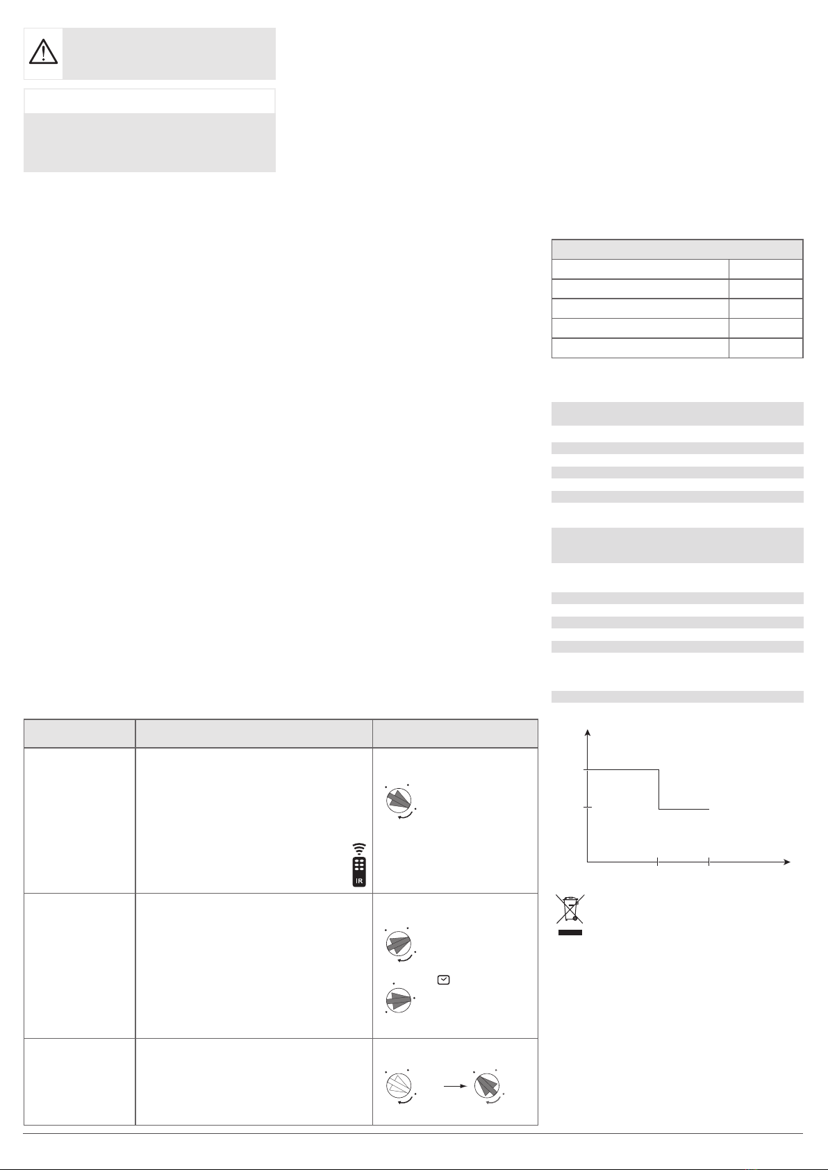
Action Settings Potentiometers
Use Auto settings
(factory) or set by
the programming
tool to switch the
light automatically
for a defined time.
Auto Settings
Put the Lux potentiometer on “auto test”.
The settings are predefined:
Lux = 400,
time = 20 min.
q: test mode for 2min.
Programming tool settings EEK001
(manual settings inhibited).
auto
test
1 min
1 h
20 min
1
on
2
lux
1 min
1 h
20 min
1
on
2
lux
auto
test
Automatically switch
on the light for a
defined time.
Installer settings
auto
test
1 min
1 h
20 min
1
on
2
lux
1 min
1 h
20 min
1
on
2
lux
1
on
2
lux 1
on
2
lux
auto
test
auto
test
auto
test
Test and validate the
detection zone.
Test mode
Move the potentiometer 1 to “auto test”.
On this position, the programming tool
EEK001 can be used.
auto
test
1 min
1 h
20 min
1
on
2
lux
1 min
1 h
20 min
1
on
2
lux
1
on
2
lux 1
on
2
lux
auto
test
auto
test
Technical characteristics
Electrical characteristics
Supply voltage 230V~ +10/-15% 50/60Hz
240V~ +/-6% 50/60Hz
Consumption with no load 2,4 VA / 270 mW
Upstream protection circuit breaker 16 A
Functional characteristics
Lighting output operating time 1 min. ➡1 h
Brightness level 5 ➡1000 Lux
Recommended installation height 2,5 ➡3,5 m
Detection range Ø 7 m
(installed product height: 2.5 m)
Fixing accessorie
Screws ( No 8), Protective cover
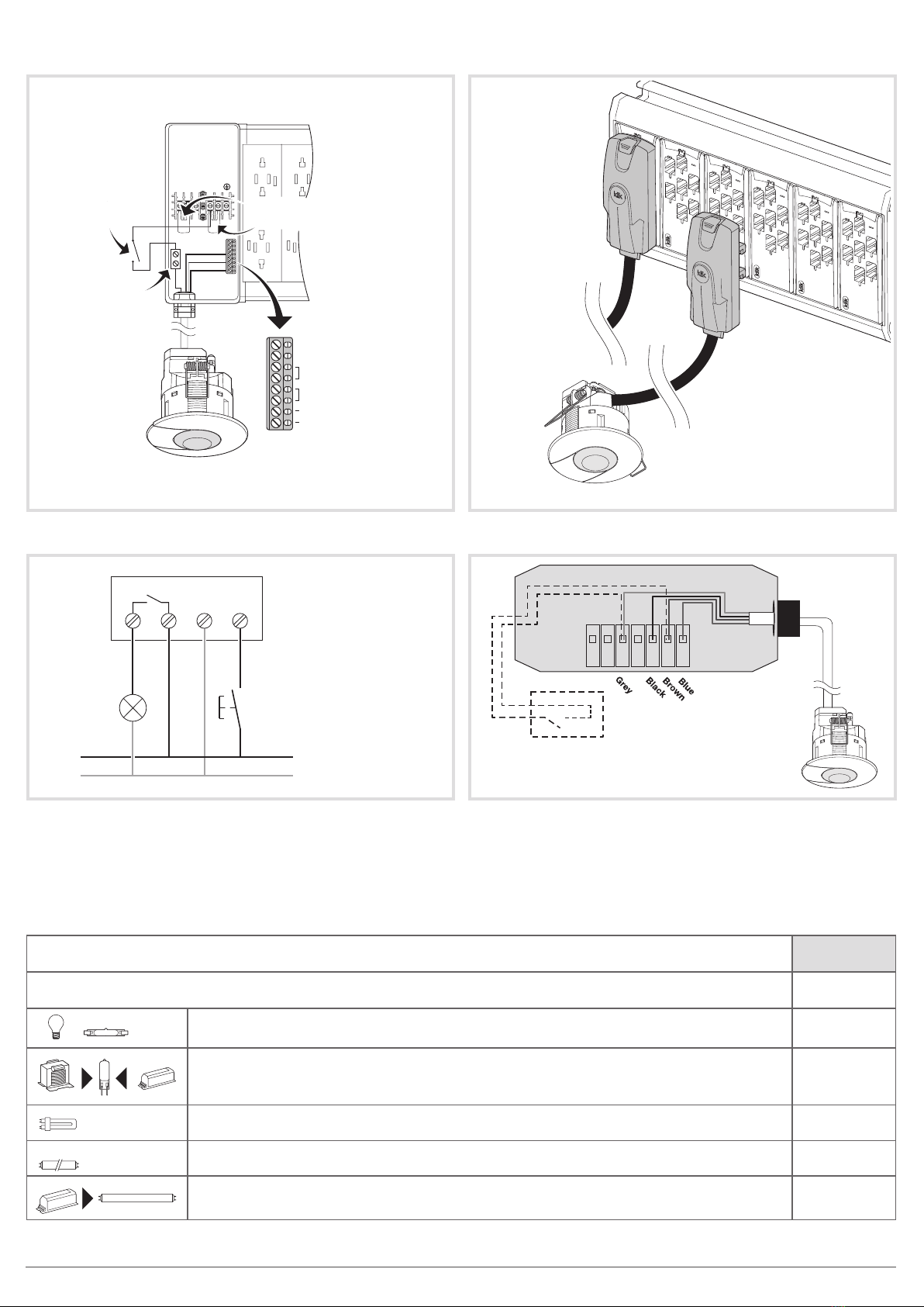
Products can be connected in parallel.
Hole size required 60 mm
Environment
Storage temperature -20 °C ➡+60 °C
Class of insulation II
IK 03
Index of protection IP41
Fire resistance 650 °C
Connection capacity (EEK510B)
0.5 mm2 to 1.5 mm2 flexible,
0.5 mm2 to 1.5 mm2 rigid
Operating altitude 2000m
Operating temperature :
Factory settings
Luminosity threshold 400 lux
Lighting time 20 min.
Mode Presence
Power Up OFF
Active cell (Luminosity Cell) ON
Functional modes
The detector has 2 dierent modes.
- Presence detection (automatic).
- Absence detection (semi-automatic).
The power up and cell operation can be set for each
mode. A normally open retractive switch connected
to the product makes it possible to reverse the
lighting output state.
This state is maintained for the time period set
by the potentiometer 2or the programming tool
EEK001.
Presence detection (automatic mode)
In this mode the light is controlled by motion in the
detection area and ambient light levels.
If presence is detected whilst the light levels are
below the required Lux level, the sensor is activated
and keeps the light on whilst there is still occupancy
and for the time out period afterwards. Once the
sensor has deactivated the lights, it will require
a new occupancy whilst the ambient light levels
are below the required Lux levels to activate the
lights again. This mode can be changed via the IR
remote control EEK001 (default mode is presence
detection: automatic).
Absence detection (semi automatic mode)
The sensor needs to be activated by a normally
open retractive switch or a user remote control
input. Once the sensor is activated, it will hold the
lights on whilst there is still occupancy and for the
time out period afterwards. Once the sensor has
deactivated the lights, it will require another input
from the wallswitch or the programming tool to
switch the lights on.
Power Up
A parameter of the detector allows the choice of
state for the lighting after power up (mains return).
During warm up phase, the green LED blinks. In the
Power up ON state, the lighting will automatically be
energised when mains power is initially supplied or
returned to the sensor. In the Power up OFF state,
the lighting will not be energised and the sensor will
not operate during warm up period. This parameter
is modified using the installer programming tool
EEK001.
POWER UP state:
• ON: the light is immediately switched on for 30 s
after power up. In case of detection, the light
(in automatic mode) remains on during the time
delay; otherwise the light is switched o.
• OFF: the detector switches to the selected mode
after warm up.
Active / passive cell
Active cell
The photocell will inhibit the output from the sensor
if the ambient light level is sucient.
If the sensor detects occupancy whilst the ambient
light level is below the required Lux level, the lights
will be activated. However if the ambient light level
increases to a value where it is above the required
Lux level during a certain time, the sensor will
detect it and switch o the light.
Passive cell
The photocell will inhibit the output from the sensor
if at the time of detection the ambient light level is
sucient. In case of detection, if the ambient light
level increases, the photocell will not turn o the
light.
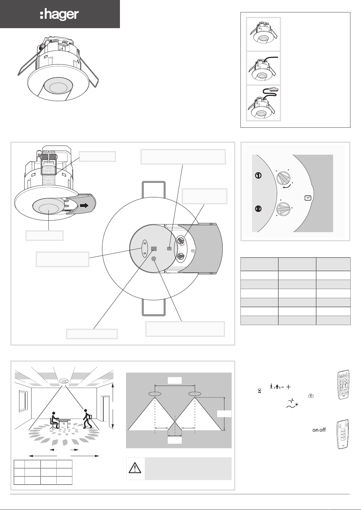
Product description
and operating principles
Occupancy sensors EEK are designed to detect
low level movements (e.g. person sitting at a desk).
Dierent models are available:
- without lead: EEK510B for standalone and BESA
mounting
- with pre-wired lead (3 m): EEK513W to be
interfaced with the KLDS marshalling boxes
- with pre-wired lead (3 m or 5 m) and klik.system
plug to be interfaced with the KLMB marshalling
boxes: EEK513P, EEK515P.
Detection is by means of a pyroelectric sensor
located under the detection lens.
The occupancy sensor measures the brightness in
the room on a continuous basis and compares it to
the level preset on the potentiometer (or by means
of the programming tool EEK001).
Settings
The Lux threshold and time out period can be set
with the potentiometers or by using the installer
programming tool (EEK001).
Test Mode - Walk test
This mode makes it possible to validate the
detection area. To select this mode, set the
potentiometer 1to the position “auto test”. The
green or red LED behind the lens is on for 2 seconds
after detection. The red LED indicates that the light
level measured is lower than current setting. If the
green LED is on, the light level measured is higher
than current setting.
There is a time out of 2 minutes which is reactivated
after each detection. The output is also switched
during 2 s. after each detection.
It is also possible to use the programming tool
EEK001 to set the detector in test mode.
This device must be installed by a suitably
qualified electrician according to the installa-
tion’s standards.
Correct Disposal of This product
(Waste Electrical & Electronic
Equipment)
(Applicable in the European Union and other European
countries with separate collection systems).
This marking shown on the product or its literature indicates
that it hould not be disposed with other household wasted at
the end of its working life. To prevent possible harm to the envi-
ronment or human health from uncontrolled waste disposal,
please separate this from other types of wastes and recycle it
responsibly to promote the sustainable reuse of material re-
sources.
Household users should contact either the retailer where they
purchased this product, or their local government oce, for
details of where and how they can take this item for environ-
mentally safe recycling.
Business users should contact their supplier and check the
terms and conditions of the purchase contract. This product
should not be mixed with other commercial wastes of disposal.
Usable throughout Europe
å
and in Switzerland
Hager Controls hereby declares that the PIR Occupancy
Sensorsdevice complies with the essential requirements
and other relevant provisions of Directive 2014/53/EU.
The CE declaration is available on the:
www.hagergroup.com
16A
40°C 45°C
Temperature (C°)
Amperes (A)
10A
2 6LE000505C