manuals.online logo
Brands
  1. Home
  2. •
  3. Brands
  4. •
  5. SeaLevel
  6. •
  7. Recording Equipment
  8. •
  9. SeaLevel ACB-188 User manual

SeaLevel ACB-188 User manual

ACB-188™
PART # 4019
USER MANUAL
SECTIONS:
1. Installation
2. Address Selection
3. Option Selection
4. Technical Description
5. Product Specifications
6. Warranty
7. Appendix A
FIGURES:
1. Address Selection Table
2. Dip Switch (SW1) Illustration
3. Header E2 -IRQ Selections
4. Header E3 -IRQ Mode Selections
5. Header E1 -RTS Enable Selections
6. Header E4 -MIL-188-114 Selection and Connector Pin-Outs
7. Header E4 -MIL-188-C Selection and Connector Pin-Outs
8. Header E4 -MIL-188-200 Selection and Connector Pin-Outs
Sealevel Systems, Incorporated
155 Technology Place
P.O. Box 830
Liberty, SC 29657 USA
(864) 843-4343 FAX (864) 843-3067
© 1996d Sealevel Systems, Incorporated
__________________________________________________________________________
Sealevel Systems ACB-188 Page 1
SECTION 1. Installation
The ACB-188 can be installed in any of the PC expansion slots. Remove the PC case,
remove the blank metal slot cover, and insert the board. Replace the screw, replace the case,
and installation is complete.
Be sure to set the address and jumper options before installation.
SECTION 2. Address Selection
The ACB-188 occupies 8 consecutive I/O locations. A DIP-switch (SW1) is used to set the
base address for these locations. Be careful when selecting the base address as some
selections conflict with existing PC ports. The following table shows several examples that
usually do not cause a conflict.
Address Binary Switch Settings
Hex A9-----------A0 1234567
238-23F 1000111XXX Off On On On Off Off Off
280-287 1010000XXX Off On Off On On On On
2A0-2A7 1010100XXX Off On Off On Off On On
2E8-2EF 1011101XXX Off On Off Off Off On Off
300-307 1100000XXX Off Off On On On On On
328-32F 1100101XXX Off Off On On Off On Off
3E8-3EF 1111101XXX Off Off Off Off Off On Off
TYPICALLY COM1:=3F8h; COM2:=2F8h; COM3:=3E8h; COM4:=2E8h.
Figure 1
Address Selection Table
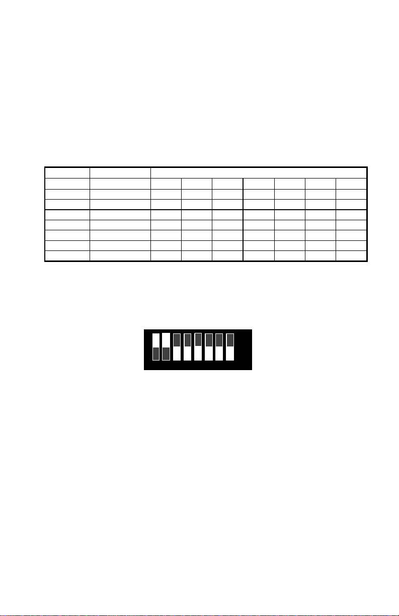
The following illustration shows the correlation between the DIP-switch setting and the
address bits used to determine the base address. In the example below, the address 300
Hex through 307 Hex is selected. 300 Hex =11 0000 0XXX in binary representation.
ON
OFF
1 2 3 4 5 6 7
`A9 A3
8
EN
Figure 2
DIP-switch SW-1
Note: Setting the switch "On" or "Closed" corresponds to a "0" in the address, while leaving it
"Off" or "Open" corresponds to a "1".
The ACB-188 can be enabled or disabled with switch position 8 on the DIP-switch. The port
is enabled with the switch "On" or "Closed" and disabled when "Off" or "Open".
The relative I/O address of the 8530 SCC registers is as follows:
•Base+0 Channel A Data Port
•Base+1 Channel A Control Port
•Base+2 Channel B Data Port
•Base+3 Channel B Control Port
Where "Base" is the selected board base address.
__________________________________________________________________________
Sealevel Systems ACB-188 Page 2
SECTION 3. Option Selection
The board contains several jumper straps which must be set for proper operation. For jumper
locations, refer to the silk-screen diagram in the back of this manual.
IRQ Selection
E2 -Selects the interrupt request for the ACB-188.
15 12 11 10 7 6 5 4 3 2
Figure 3
Header E2, IRQ 4 Selected
Interrupt Modes
Figure 4.1 illustrates the Normal, single interrupt per port mode. Figure 4.2 illustrates the
Shared interrupt mode, which allows more than one port to access a single IRQ. Figure 4.3
indicates the Multi-port mode that signifies inclusion of a 1K ohm pull-down resistor required
on one port when sharing interrupts.
1
Normal
Figure 4.1:
Header E3 Illustration Part 1.
__________________________________________________________________________
Sealevel Systems ACB-188 Page 3
Figure 4.2 illustrates the Shared interrupt mode, which allows more than one port to access a
single IRQ.
Note: Setting the ACB-188 in this configuration when it is not accompanied by a pull-down
resistor (see Figure 4.3) will prevent the ports from triggering an interrupt.
1
Shared
Figure 4.2
Header E3 Illustration Part 2.
If shared interrupts are required on two or more ACB-188’s set the jumpers for shared
interrupt mode on all ports sharing an IRQ except one. Set that port block as the example
4.3. This provides the pull-down resistor circuit that makes sharing of IRQ’s possible. If you
are using more than one ACB-188 or a compatible card in a bus you should only have one
port set as Figure 4.3.
1
Multi
Figure 4.3
Header E3 Illustration Part 3.
__________________________________________________________________________
Sealevel Systems ACB-188 Page 4
E1 -On port 1 to have the driver enabled by RTS place the jumper at the “RTS” A position.
To have the driver always enabled or always on place the jumper at the “ON” A position. On
port 2 to have the driver enabled by RTS place the jumper at the “RTS” B position. To have the
driver always enabled or always on place the jumper at the “ON” B position.
E1
1RTS
ON
RTS
ON
A
B
Figure 5.
E4 -A unique feature of the ACB-188 is the capability to receive single ended transmissions
or differential transmissions. Placing the jumpers in the “B” position ground the unused pins
allowing single ended reception. To select differential transmissions place all jumpers in the
“B” position as shown in Figure 6. To select single ended positive (+) transmissions place
jumpers as shown in Figure 7. To select single ended negative (-) transmissions place the
jumpers as shown in Figure 8.
Signal Name DB-15 PIN #
Transmit Positive TX+ 6
Transmit Negative TX-2
Request to Send Positive RTS + 5
Request to Send Negative RTS -4
Receive Data Positive RD+ 8
Receive Data Negative RD-3
Receive Clock Positive RXC + 9
Receive Clock Negative RXC -10
Ground GND 7
“Push to Talk” PTT 15
Figure 6
MIL-188-114 Differential
Signal Name: DB-15 PIN #
Transmit TX 6
Request to Send RTS 5
Receive Data RD 8
Receive Clock RXC 9
Ground GND 7
“Push to Talk” PTT 15
Figure 7
MIL-188-C Single Ended Positive Logic
AB
E4
1
AB
E4
1
__________________________________________________________________________
Sealevel Systems ACB-188 Page 5
Signal Name: DB-15 PIN #
Transmit TX 2
Request to Send RTS 4
Receive Data RD 3
Receive Clock RXC 10
Ground GND 7
“Push to Talk” PTT 15
Figure 8
MIL-188-200 Single Ended Negative Logic
SECTION 4 Technical Description
The Sealevel Systems ACB-188 provides the PC with two high speed Sync / Async ports.
The ACB-188 can be used in a variety of sophisticated communications applications such as
SDLC, HDLC, X.25, and high speed Async.
Features include:
•Two channels of Sync / Async communications using 8530 .
•Selectable port address and IRQ level (2-7, 10, 11, 12, 15)
•Direct connection to SINCGARS Military Radio digital interface
The ACB-188 utilizes the Zilog 8530 Serial Communications Controller (SCC). This chip
features programmable baud rate, data format and interrupt control. Refer to the 8530
Technical Manual for details on programming the 8530 chip.
Internal Baud Rate Generator
The baud rate of the SCC is programmed under software control. The standard oscillator
supplied with the board is 4.9152 MHz. However, other oscillator values can be substituted to
achieve different baud rates.
ACB Developer Toolkit Diskette and the ACB Resource Kit
The ACB Developer Toolkit diskette provides sample software and technical insight to aid in
the development of reliable applications and device drivers for the ACB family of
communication cards. The goal in publishing this collection of source code and technical
information is two fold. First is to provide the developer with ample information to develop ACB
based applications. Second is to provide a channel for suggestions into the technical support
efforts. The ACB Resource Kit provides a brief overview of the ACB product line. Topics
concerning applications and integration are covered to provide a complete overview of the
versatile ACB family. During ACB development, any questions, comments, suggestions, or
requests for the ACB Resource Kit Literature should be directed to Sealevel Systems
Technical Support at the numbers listed at the end of this manual.
AB
E4
1
__________________________________________________________________________
Sealevel Systems ACB-188 Page 6
SECTION 5. Specifications
Environmental
Specification Operating Storage
Temperature range 0 -50 Degrees C
32 -122 Degrees F-20 -70 Degrees C
-40 -100 Degrees F
Humidity Range 0-90% R.H.
Non-Condensing 0-90% R.H.
Non-Condensing
Performance
MTBF > 150,000 Hours
MTTR < .25 Hours
Turnaround for repair -5 working days
Manufacturing
•Adherence to IPC 610-A Class-III standards with a 0.1 visual A.Q.L. and 100% functional
testing.
•Boards are built to U.L. 94V0 rating and are 100% electrically tested. Boards are solder
mask over bare copper or solder mask over tin nickel.
Power
Supply Line +5 -5
Rating (mA) 420 mA 50 mA
__________________________________________________________________________
Sealevel Systems ACB-188 Page 7
SECTION 6. WARRANTY
Sealevel Systems, Inc. provides a lifetime warranty for this product. Should this
product fail to be in good working order at any time during this period, Sealevel
Systems will, at it's option, replace or repair it at no additional charge except as
set forth in the following terms. This warranty does not apply to products
damaged by misuse, modifications, accident or disaster.
Sealevel Systems assumes no liability for any damages, lost profits, lost
savings or any other incidental or consequential damage resulting from the use,
misuse of, or inability to use this product. Sealevel Systems will not be liable
for any claim made by any other related party.
Return Authorization Must Be Obtained From Sealevel Systems Before
Returned Merchandise Will Be Accepted. Authorization Can Be Obtained By
Calling Sealevel Systems And Requesting A Return Merchandise
Authorization (RMA) Number.
Sealevel Systems, Incorporated
155 Technology Place
P.O. Box 830
Liberty, SC 29657 USA
(864) 843-4343 FAX (864) 843-3067
E-mail: [email protected]
Internet: www.sealevel.com
Sealevel Systems Incorporated acknowledges that all trademarks referenced in this manual
are the service mark, trademark, or registered trademark of the respective company.
ACB-188 Serial Interface is a trademark of Sealevel Systems Incorporated.
__________________________________________________________________________
Sealevel Systems ACB-188 Page i
Appendix A
SINCGARS Specific Application Notes:
Recommended Cabling
The following connections are made to directly interface to a SINCGARS Military Radio.
Please note that the Mode pin is connected to ground (GND) to select digital data mode.
SINCGARS Description ACB-188
AGND 7
BRx Data 3
CPTT 15
DData Clock 10
EMode 7
FTx Data 2
Push To Talk (PTT)
The interface signal Push To Talk (PTT) is asserted by the systems software to request a
transmit clock from the SINCGARS radio. PTT is activated by asserting Request To Send
(RTS) on the SCC (WR5 bit D1).
Clock Detect
The ACB-188 implements a clock detect circuit that functions as a “missing pulse detector”.
This utilizes a “one shot” circuit that generates a low or active signal on DCD when a clock is
present, or when its connected to a device generating a 400 Hz or greater signal. A high or
inactive signal will be present at DCD when no clock is detected (missing pulse) or a device
generating a signal less than 400 Hz. The software can poll the status of DCD through Read
Register 0 (RR0 bit D3) or program the SCC for External Status Interrupts and the 8530 will
generate an interrupt every time DCD changes states.
Software Summary:
Once the proper cable connections have been made to the SINCGARS radio the software
should program the SCC to interrupt on external status for DCD. This will allow the software
to detect the presence of a clock signal. The software algorithm for transmit should allow RTS
to be asserted if CTS is active. Once RTS is asserted the DCD input should be pulsing before
the transmission is started. For receive, the DCD pin will be pulsing when the receive data
stream is sent from the radio.

This manual suits for next models

1

Other SeaLevel Recording Equipment manuals

SeaLevel DIO-104.OPTO User manual

SeaLevel

SeaLevel DIO-104.OPTO User manual

SeaLevel PC-SIO-232 User manual

SeaLevel

SeaLevel PC-SIO-232 User manual

SeaLevel SeaLINK+4.VC User manual

SeaLevel

SeaLevel SeaLINK+4.VC User manual

SeaLevel COMM+8.LPCI User manual

SeaLevel

SeaLevel COMM+8.LPCI User manual

SeaLevel ULTRA 485 User manual

SeaLevel

SeaLevel ULTRA 485 User manual

SeaLevel ISO-16.PCI User manual

SeaLevel

SeaLevel ISO-16.PCI User manual

SeaLevel COMM+8 User manual

SeaLevel

SeaLevel COMM+8 User manual

SeaLevel COMM+4.PCI User manual

SeaLevel

SeaLevel COMM+4.PCI User manual

SeaLevel 5402e User manual

SeaLevel

SeaLevel 5402e User manual

SeaLevel PC-SIO-850 User manual

SeaLevel

SeaLevel PC-SIO-850 User manual

SeaLevel PLC-16.PCI User manual

SeaLevel

SeaLevel PLC-16.PCI User manual

SeaLevel SIO-485 User manual

SeaLevel

SeaLevel SIO-485 User manual

SeaLevel COMM+8.LPCI User manual

SeaLevel

SeaLevel COMM+8.LPCI User manual

SeaLevel PC-COMM+232 User manual

SeaLevel

SeaLevel PC-COMM+232 User manual

SeaLevel PIO-96.PCI User manual

SeaLevel

SeaLevel PIO-96.PCI User manual

SeaLevel SeaLINK PIO-96 User manual

SeaLevel

SeaLevel SeaLINK PIO-96 User manual

Popular Recording Equipment manuals by other brands

PSP B-Scanner Operation manual

PSP

PSP B-Scanner Operation manual

Altinex Wall Mount Interface with Twisted Pair (TP) Output... user guide

Altinex

Altinex Wall Mount Interface with Twisted Pair (TP) Output... user guide

Roland CD-2i Brochure & specs

Roland

Roland CD-2i Brochure & specs

Xinje ZG3 Series user manual

Xinje

Xinje ZG3 Series user manual

urmet domus 1043 installation manual

urmet domus

urmet domus 1043 installation manual

ETC Gadget Setup guide

ETC

ETC Gadget Setup guide

Yamaha FX900 Operation manual

Yamaha

Yamaha FX900 Operation manual

Studio Technologies 5204 user guide

Studio Technologies

Studio Technologies 5204 user guide

Classe Audio SSP-800 user manual

Classe Audio

Classe Audio SSP-800 user manual

Livid Fader Box Building Guide

Livid

Livid Fader Box Building Guide

Agilent Technologies G1590A installation guide

Agilent Technologies

Agilent Technologies G1590A installation guide

QRS PNO3WB instructions

QRS

QRS PNO3WB instructions

Meicheng MT-101 user manual

Meicheng

Meicheng MT-101 user manual

Optimal Audio Zone 4 user guide

Optimal Audio

Optimal Audio Zone 4 user guide

Mitsubishi Electric DX-TL4516U series Installer manual

Mitsubishi Electric

Mitsubishi Electric DX-TL4516U series Installer manual

HMS IXXAT iPC-I XC16/PCIe manual

HMS

HMS IXXAT iPC-I XC16/PCIe manual

Infineon EZ-USB BT.1120/LVDS quick start guide

Infineon

Infineon EZ-USB BT.1120/LVDS quick start guide

COBHAM AA95-1000TSO Installation and operation manual

COBHAM

COBHAM AA95-1000TSO Installation and operation manual

manuals.online logo
manuals.online logoBrands
  • About & Mission
  • Contact us
  • Privacy Policy
  • Terms and Conditions

Copyright 2025 Manuals.Online. All Rights Reserved.