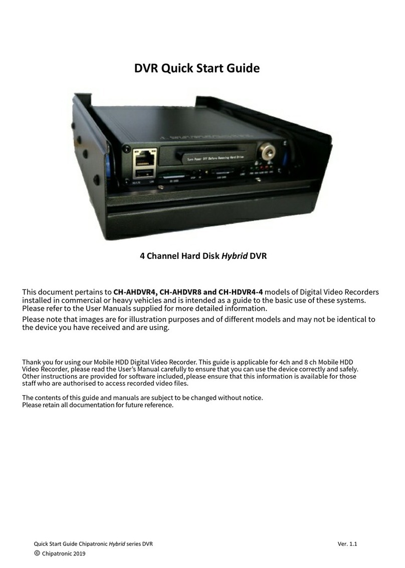
Chipatronic CH-AHDVR4 User manual

Installation Instructions for Hybrid Digital Video Recorder models:
CH-AHDVR4 - CH-AHDVR8 - CH-HDVR4-4
●These instructions are intended as a guide to assist in the installation of the DVR systems and assumes that the
installer has sufficient knowledge of auto electrical principles and practices to competently carry out all work
required. Should any part of the work required not be clearly understood this installation should be ceased and a
suitable installer engaged.
●If you are not familiar with these DVR systems it is strongly recommended that before commencing installation on a
vehicle that a bench test is done with all components to confirm connections and operation.
Once this has been done you may proceed with the vehicle installation with clarity.
●Any damage to equipment during installation is not covered by warranty and no work should be attempted without
first determining that this is the most appropriate method of installation as certain parts of the work will require
drilling holes to mount equipment.
●The position of cameras should be determined prior to any cables being run and then cable paths will need to be
mapped out to ensure that these can be installed without the likelihood of damage and that cables are sufficiently
long enough to reach the main DVR.
●Cables should be run through standard channels and grommets where possible. Protection such as split conduit
may be used to provide mechanical protection if necessary. Cutting plugs off cables or cameras to assist in
installation is not recommended as signal loss or interference may be present after re-connection.
●If using HDD the DVR should always be mounted horizontally as the vibration dampening mechanism will not afford
suitable protection for the hard drive in other positions. Users mounting the DVR in other ways do so at their own
risk. If unable to mount horizontally it is recommend to use SSD.
●Never mount the DVR where it cannot get airflow as the device requires air for cooling. Covering the DVR while in
use or mounting in a location where no airflow is possible may cause damage to the DVR.
●Never mount the DVR where it can be affected by water.
●Never mount the DVR where it will be subjected to excessive heat and vibration.
●If the DVR is to be used with components or accessories which are not supplied as standard equipment this shall be
at the user’s own risk. Any fault caused by the use of equipment not supplied with the system will not be covered by
warranty.
●Do not clean the equipment with solvents or other chemicals. Never use high pressure air to attempt to clean inside
the device.
●Should any repairs be required, please return the equipment to the place of purchase.
Please refer to the Quick Start Guide and User Manual for further details and information, Manual is included or may be
downloaded from www.chipatronic.com.au website.
DVR are supplied fully configured and tested and should not need further setup. It is not recommended that untrained
users have access to the system menu. If system parameters changes are required, please ensure that only the selected
parameters are altered and that changes are tested before returning the system to normal use.
Important notice:

GPS Connection (Optional)
Alarm/Sensor Inputs x 3 (Grey)
Alarm is generated when high (12 or 24V) signal is connected.
Sensor 1 can be set to activate the monitor to show the rear cam for reversing.
This must be connected to Trigger 1 on the monitor cable and to the reverse light
circuit on the truck.
The GPS antenna should be mounted so that it will line-of-sight to
the sky and must not be shielded by metal.
Keep away from high power wiring and any other antennas as the
signal may be disrupted.
The only electrical connections required are shown below. Always ensure that the power is supplied through a fuse,
either the one provided or other fuse of the same rating.
Ensure that earthing is well bonded to the main battery earth system.
12 or 24V power is suitable, there is no need to select voltage.
A CVBS Video Output cable is supplied and should be connected to the Vᵒᵘᵗ port and can be left in place with the
connection accessible from the front to allow for a monitor to be connected when necessary.
HDMI output is also available for use with HDMI monitors and may provide higher quality images.
Model CH-HDVR4-4 has 4
HD camera inputs and 4
analogue camera inputs.
Model CH-AHDVR4 has 4
analogue camera inputs
only.
Modelo CH-AHDVR8 has
8 analogue camera
inputs and 1 HD camera
input
All other items are the
same on all models.
Wireless (3G)/4G Antenna (only with 3G or 4G systems).
Ensure that the antenna is mounted away from other antennas and
high power wiring.
Analogue cameras can be CVBS or AHD. Connections are by 2 multi-pin
connectors each having 2 4 pin aviation connectors (male) to allow use
of standard extension cables and cameras.
Each pair, 1 & 2 or 3 & 4 must be the same camera type, AHD or CVBS.
Video modes cannot be mixed in the pairs but
the 2 pairs can each be different if required.
AHD cameras will give much better video
quality and are recommended for new
installations.
Normally only REAL image cameras are used
with DVRs as the video files must be able to be
viewed normally. Some cameras supplied will be MIRROR image by
default but will have means to change this to REAL. Please check the
instructions provided with the camera for further information.
It is recommended to check cameras with a test monitor if the image
output is not confirmed.

Rear Panel CH-HDVR4-4 (8 Channel)
①:Power (including Power, Ground, Ignition).
②:Camera 5 and 6(including power for camera)
③:Camera 7 and 8(including power for camera)
④:CVBS Video and Audio Out (including power for monitor)
⑤:HDMI Out
⑥:Camera 3(including power for camera)
⑦:Camera 4(including power for camera)
⑧:Camera 2(including power for camera)
⑨:Camera 1(including power for camera)
⑩:3 sensors, 1 RS232 (For GPS), 5V DC output, 1 LANC input
⑾:4G/3G antenna
1. Power (including Power, Ground, Ignition).
2. Camera 1 and 2 (including power for camera) AHD or CVBS cameras only
3. Camera 3 and 4 (including power for camera) AHD or CVBS cameras only
4. CVBS Video Out to Monitor (including power for monitor)
5. HDMI Out to HDMI Monitor
6. Sensor Connector: 3 Alarm/Sensor wires (Grey), GPS (3 pin plug), Speed sensor (Purple)
7. 4G/3G antenna (only on 3G / 4G models)
The CH-AHDVR8 model has 4 camera input sockets (2, 3) with 2 camera connection on each for total of 8
analogue cameras. There is 1 HD Digital camera input which can be used but this must be configured in the
SETTINGS and will not normally be active unless specified at the time of order.
Rear Panel CH-AHDVR4 (4 Channel)

Regardless of the vehicle type the the normal layout of a DVR system will remain similar with the main DVR mounted in
the cabin area where access to power is possible. All cameras will be connected by cables and these will need to be run
through cable channels where possible and should be fixed into place so that they cannot be inadvertently caught and
damaged.
Trucks with “cab over” layout will require the cables going outside of the cab to be run with other wiring through pivot
points.
The DVR is supplied in a metal chassis which needs to be firmly mounted. Remove the DVR from chassis and attach using
suitable fixings allowing sufficient room to access the rear panel where the connections are made.
Always ensure that the DVR is accessible so the hard drive can be removed when necessary.
Cables should be left with enough slack to allow the DVR to be removed. Do not tightly bunch the cables close to the DVR
as this may place undue strain on the connectors and will hamper access in the future.
Different cameras will be used depending on the vehicle and application, it is recommended that standard cameras
supplied by Chipatronic are used as these have been tested with the system and are high resolution models suitable for
automotive video recording applications.
Camera mounting will be subject to the cameras used and the vehicle. Installers should check with the vehicle operator
before commencing installation to ensure that these are able to capture the required views.
A portable camera tester is available to assist in setting up cameras and to connect to the DVR to check operation and
setup. Contact Chipatronic for details.
Sensor input 3 Grey wires
Connect Sensor 1 wire to the Trigger
1 wire on the monitor (Brown) and
then to the Reverse light circuit.
When the truck goes into Reverse
the monitor will turn ON and show
the rear camera (CAM 4).
DVR
Video
Out
Connect the Brown wire (Trigger 1) on the monitor
cable to Sensor 1 and Reverse lights
DVR Video Out must connect to AV1
(CAM1) on the monitor
Using DVR Video Out as a Reverse Camera
The DVR has 2 different video outputs; HDMI and CVBS. For a Reverse Cam application only a CVBS monitor can be used.
The DVR will have been configured for this functionality prior to delivery if this was specified at time of order but it is
recommended that this operation is bench tested prior to vehicle installation to ensure that it works as expected as
additional connection to the vehicle’s electrical system will be required which cannot be tested.
As standard, Sensor 1 will be the DVR trigger input and this should be connected to Trigger 1 on the monitor.
For automatic operation in reverse gear, this must be connected to the reverse light circuit so that a voltage signal is
applied to both of these triggers together. The monitor will usually be in standby mode (powered off using the button on
the monitor) and will turn on when voltage is applied with AV1 (Ch. 1) being displayed which will be a single camera
output from the DVR, usually Ch. 4 which should be the rear camera. Please ensure that cameras are connected to the
correct DVR inputs as specified or the incorrect image will be shown.
Up to 3 cameras can be switched in this manner to achieve specific views on selection from the DVR but must be
configured in the DVR settings. This is best done prior to the system being supplied but can be done later if required.

CAMERA TYPE CABLE PART NUMBER DESCRIPTION
HD CH-HDVC3 3m extension cable for HD cameras
HD CH-HDVC6 6.2m extension cable for HD cameras
HD CH-HDVC10 9m extension cable for HD cameras
ANALOGUE CL-2MA 2m 4 pin extension cable for Analogue/AHD cameras
ANALOGUE CL-4MA 4m 4 pin extension cable for Analogue/AHD cameras
ANALOGUE CL-7MA 7.5m 4 pin extension cable for Analogue/AHD cameras
ANALOGUE CL-10MA 10m 4 pin extension cable for Analogue/AHD cameras
Analogue CL-10MH Heavy Duty 10m extension cable for Analogue/AHD cameras
ANALOGUE CL-15MA 15m 4 pin extension cable for Analogue/AHD cameras
ANALOGUE CL-20MA 20m 4 pin extension cable for Analogue/AHD cameras
Camera extension cables are required to connect the cameras to the DVR and a standard range of cables are available.
HD cameras (where used) require different cables to standard, analogue cameras (whether CVBS or AHD).
Please select cables of sufficient length to allow connection back to the DVR via the most suitable path to ensure the
cables will not be subject to damage.
Where cables will be part of a moving system the cables must not be subjected to strain or stretching as this will lead to
cable failure.
Connections can be damaged by moisture especially in coastal environments and the use of a dielectric grease or spray
to prevent moisture ingress is recommended.
Only available on 8
Ch. systems
This manual suits for next models
2
Other Chipatronic DVR manuals
