Siel Green Point 6 20KVA User manual
IV319 Rev.00
Data 2010-06-22 Pag. 1 di 118
USER MANUAL
0$18$/('·862e INSTALLAZIONE
UPS / Gruppi statici di continuità
Models Green Point 6÷20KVA
Uninterruptible Power System

IV319 Rev.00
Data 2010-06-22 Pag. 2 di 118
CONTENTS
1. Safety and EMC instructions ··························································· 6
1.1 INSTALLATION············································································6
1.2 OPERATION ················································································7
1.3 MAINTENANCE,SERVICING AND FAULTS ····································8
1.4 TRANSPORT················································································ 9
1.5 STORAGE···················································································· 9
1.6 STANDARDS ··············································································· 9
2.1 Description of commonly used symbols···································· 10
2.2 Description of commonly used name for phase ······················· 11
3. Introduction ····················································································· 12
3.1 SYSTEM AND MODEL DESCRIPTION···········································12
3.2 PRODUCT SPECIFICATION AND PERFORMANCE ·························13
4. Display Panel ··················································································· 16
5. Installation························································································ 20
5.1 UNPACKING AND INSPECTION··················································· 20
5.2 INPUT AND OUTPUT POWER CORDS AND PROTECTIVE EARTH
GROUND INSTALLATION·································································· 20
5.3 OPERATING PROCEDURE FOR CONNECTING THE LONG BACKUP
TIME MODEL UPS WITH THE EXTERNAL BATTERY ·························· 25
5.4 PARALLEL OPERATION ······························································ 26
6. Operation ························································································· 32
6.1 OPERATION MODE ···································································32
6.2 PARALLEL OPERATION ·····························································34
6.3 BACKUP TIME FOR THE STANDARD MODEL ·······························39
7. Battery Maintenance ······································································· 40
8. Notes for Battery Disposal and Battery Replacement ················ 41
9. Trouble Shooting············································································· 42

IV319 Rev.00
Data 2010-06-22 Pag. 3 di 118
10. Operating mode for all models ···················································· 44
10.1 NO OUTPUT MODE ·································································45
10.2 BYPASS MODE ········································································45
10.3 LINE MODE·············································································46
10.4 BATTERY MODE /BATTERY TEST MODE··································47
10.5 PARALLEL MODE ···································································· 48
10.6 WARNING MODE·····································································48
10.7 FAULT MODE ··········································································49
10.8 EPO MODE············································································· 51
11. Setting by LCD Module ································································· 52
12. Communication Port····································································· 56
12.1 RS232 INTERFACE ·································································56
12.2 INTELLIGENT SLOT ································································· 56
12.3 AS400 INTERFACE (OPTION)··················································56
13. Software for all models································································· 58
Appendix 1: The Corresponding Form of the LCD Display············ 59
Appendix 2: Rear Panel ······································································ 60
1. Istruzioni relative alla sicurezza e alla EMC································· 63
1.1 INSTALLAZIONE········································································63
1.2 UTILIZZO··················································································64
1.3 MANUTENZIONE,RIPARAZIONE E GUASTI·································64
1.4 TRASPORTO·············································································· 65
1.5 STOCCAGGIO············································································66
1.6 STANDARD ··············································································· 66
'HVFUL]LRQHGHLVLPEROLG¶XVRFRPXQH······································ 67
2.2 Descrizione dei nomi delle 3 fasi usati nel manuale················· 68
3. Introduzione····················································································· 69
3.1 DESCRIZIONE DEL SISTEMA E DEL MODELLO ····························69

IV319 Rev.00
Data 2010-06-22 Pag. 4 di 118
3.2 SPECIFICHE E PRESTAZIONI DEL PRODOTTO ······························ 70
4. Descrizione del pannello del display ············································ 73
5. Installazione····················································································· 77
5.1 DISIMBALLAGGIO E ISPEZIONE ·················································77
5.2 INSTALLAZIONE DEI CAVI DI ALIMENTAZIONE IN ENTRATA E IN
USCITA E MESSA A TERRA DI PROTEZIONE ·······································77
5.3 PROCEDURA OPERATIVA PER COLLEGARE GLI UPS ALLA
BATTERIA ESTERNA OVE PREVISTA. ················································82
5.4 FUNZIONAMENTO IN PARALLELO·············································· 83
6. Funzionamento················································································ 89
6.1 MODALITÀ OPERATIVA ·····························································89
6.2 FUNZIONAMENTO IN PARALLELO·············································· 91
6.3 IL TEMPO DI AUTONOMIA PER IL MODELLO STANDARD··············96
7. Manutenzione della batteria··························································· 97
8. Note per lo smaltimento e la sostituzione delle batterie ············ 98
9. Risoluzione dei problemi································································ 99
10. Modalità operative per tutti i modelli ········································ 102
10.1 MODALITÀ NO OUTPUT ·······················································103
10.2 MODALITÀ BY-PASS·····························································103
10.3 MODALITÀ NORMALE ··························································104
10.4 MODALITÀ BATTERIA /MODALITÀ TEST BATTERIA ··············105
10.5 MODALITÀ IN PARALLELO····················································106
10.6 MODALITÀ ALLARME ···························································106
10.7 MODALITÀ ERRORE······························································107
10.8 MODALITÀ EPO (EMERGENCY POWER OFF) ·······················108
11. Impostazioni tramite modulo LCD············································· 109
12. Porte di comunicazione······························································ 113
12.1 INTERFACCIA RS232···························································· 113

IV319 Rev.00
Data 2010-06-22 Pag. 5 di 118
12.2 INTELLIGENT SLOT ······························································· 113
12.3 INTERFACCIA AS400 (OPZIONALE) ······································ 114
13. Software per tutti i modelli························································· 115
Appendice 1: Legenda del display LCD ········································· 116
Appendice 2: Pannello posteriore··················································· 117

IV319 Rev.00
Data 2010-06-22 Pag. 6 di 118
1. Safety and EMC instructions
Please read carefully the following user manual and the
safety instructions before installing the unit or using the unit!
1.1 Installation
ღCondensation may occur if the UPS is moved directly from a cold to
a warm environment. The UPS must be absolutely dry before
being installed. Please allow an acclimatization time of at least two
hours.
ღDo not install the UPS near water or in damp environment.
ღDo not install the UPS where it would be exposed to direct sunlight
or near heat.
ღ'RQRWEORFNYHQWLODWLRQRSHQLQJVLQWKH836¶VKRXVLQJ
ღPlace cables in such a way that no one can step on or trip over
them.
ღUPS has provided earthed terminal, in the final installed system
configuration, equipotential earth bonding to the external UPS
battery cabinets.
ღAn integral single emergency switching device which prevents

IV319 Rev.00
Data 2010-06-22 Pag. 7 di 118
further supply to the load by the UPS in any mode of operation
should be provided in the building wiring installation.
ღAn appropriate disconnect device as short-circuit backup protection
should be provided in the building wiring installation.
ღFor three-phase equipment connection to an IT power system, a
four-pole device which disconnect all phase conductors and the
neutral conductor should be provided in the building wiring
installation.
ღThis is permanently connected equipment , it must be installed by
qualified maintenance personnel.
ღEarth connection essential before connecting to the building wiring
terminal.
1.2 Operation
ღDo not disconnect the earth conductor cable on the UPS or the
building wiring terminals in any time since this would cancel the
protective earthing of the UPS system and of all connected loads.
ღThe UPS output terminal block may be electrically lived even if the
UPS system is not connected to the building wiring terminal.
ღIn order to fully disconnect the UPS, first press the OFF button,
then disconnect the mains lead.
ღEnsure that no liquid or other foreign objects can enter the UPS.
ღThe UPS can be operated by any individuals with no previous
experience.

IV319 Rev.00
Data 2010-06-22 Pag. 8 di 118
1.3 Maintenance, servicing and faults
ღThe UPS operates with hazardous voltages. Only qualified
maintenance personnel may carry out repairs.
ღCaution - risk of electric shock. Even after the unit is disconnected
from the mains power supply (building wiring terminal),
components inside the UPS are still connected to the battery,
which are potentially dangerous.
ღBefore carrying out any kind of service and/or maintenance, please
disconnect the batteries. Verify that no current is present and no
hazardous voltage exists in the capacitor or BUS capacitor
terminals.
ღBatteries must be replaced only by qualified personnel.
ღCaution - risk of electric shock. The battery circuit is not isolated
from the input voltage. Hazardous voltages may occur between the
battery terminals and the ground. Verify that no voltage is present
before servicing!
ღBatteries have a high short-circuit current and pose a risk of shock.
Take all precautionary measures specified below and any other
measures necessary when working with batteries:
᧩remove all jewellery, wristwatches, rings and other metal
objects.
᧩use only tools with insulated grips and handles.
ღWhen changing batteries, replace with the same quantity and the
same type of batteries.
ღDo not attempt to dispose of batteries by burning them. It could
cause explosion.
ღDo not open or destroy batteries. Effluent electrolyte can cause
injury to the skin and eyes. It may be toxic.
ღPlease replace the fuse only by a fuse of the same type and of the

IV319 Rev.00
Data 2010-06-22 Pag. 9 di 118
same amperage in order to avoid fire hazards.
ღDo not dismantle the UPS, except the qualified maintenance
personnel.
1.4 Transport
ღPlease transport the UPS only in the original packaging (to protect
against shock and impact).
1.5 Storage
ღThe UPS must be stockpiled in the room where it is ventilated and
dry.
1.6 Standards
* Safety
IEC/EN 62040-1-1
* EMI
Conducted Emission...........................:IEC/EN 62040-2
Category C3
Radiated Emission..............................:IEC/EN 62040-2
Category C3
*EMS
ESD.....................................................:IEC/EN 61000-4-2
Level 4
RS........................................................:IEC/EN 61000-4-3
Level 3
EFT...................................................... :IEC/EN 61000-4-4
Level 4
SURGE............................................... :IEC/EN 61000-4-5
Level 4
CS....................................................... :IEC/EN 61000-4-6
Level 3
Power-frequency Magnetic field.......... :IEC/EN 61000-4-8
Level 3
Low Frequency Signals........................:IEC/EN 61000-2-2
IV319 Rev.00
Data 2010-06-22 Pag. 10 di 118
Warning: This is a product for commercial and industrial application in the
second environment-installation restrictions or additional measures may be
needed to prevent disturbances.
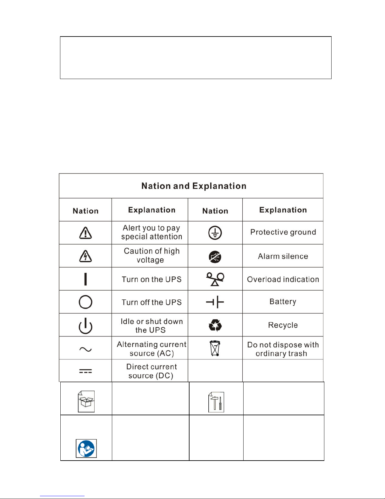
2.1 Description of commonly used symbols
Some or all of the following symbols may be used in this manual. It is
advisable to familiarize yourself with them and understand their
meaning:
This indicate how
open the package
It indicate step by step
how install the UPS
Read & understood
the manual before
operate on UPS

IV319 Rev.00
Data 2010-06-22 Pag. 11 di 118
2.2 Description of commonly used name for phase
In the UPS with 3phases input, the 3 phases are called:
³$³³%´³&³
,QWKLVPDQXDOWKHSKDVHVDUHQRUPDOO\FDOOHG³$³³%´³&³RUVRPHWLPHDUHFDOOHG³5´³6´³7³
´3KDVHA´LVsame as ³SKDVHR³or ³3KDVHL1 ³
´3KDVHB´LVVDPHDV³SKDVHS³RU³3KDVHL2 ³
´3KDVHC´LVVDPHDV³SKDVHT³RU³3KDVHL3 ³

IV319 Rev.00
Data 2010-06-22 Pag. 12 di 118
3. Introduction
3.1 System and model description
This Green Point Series is an uninterruptible power supply
incorporating double-conversion technology. It provides perfect
protection specifically for computer equipment, communication
systems to computerized instruments.
Its true online double-conversion design eliminates all mains power
disturbances. A rectifier converts the alternating current from the
utility power to direct current. This direct current charges the
batteries and powers the inverter. On the basis of this DC voltage,
the inverter generates a pure sinusoidal AC voltage, which is
constantly powering the loads.
Computers and Peripherals are thus powered entirely by the UPS.
In the event of power failure, the maintenance-free batteries power
the inverter.
This manual is applicable to the following models:
³6´0RGHO/RQJEDFNXSWLPH
Model No.
Type
Green point 6kVA 1/1
Internal Battery
Green point 10kVA 1/1
Green point 10kVA 3/1
Green point 10kVA 1/1
Green point 10kVA 3/1
External Battery
Green point 15kVA 3/1
Green point 20kVA 3/1

IV319 Rev.00
Data 2010-06-22 Pag. 13 di 118
3.2 Product Specification and Performance
1) General Specification
Model
6K 1/1
10K 1/1 (S)
10K 3/1 (S)
15K 3/1
20K 3/1
Power Rating
6KVA
4,2KW
10KVA
7KW
10KVA
7KW
15KVA
10,5KW
20KVA
14KW
Frequency (Hz)
50/60
50/60
50/60
50/60
50/60
Input
Voltage
(176-276)VAC
(176-276)VAC
(304-478)VAC
(304-478)VAC
(304-478)VAC
Current
32A max.
50A max
50A max
75A max
100A max
Battery
Voltage
240VDC
240VDC
240VDC
240VDC
240VDC
Current
24A max
40A max
40A max
60A max
80A max
Output
Voltage
208/220/230/240VAC
Current
26/27/26/25A
43/45/43/42A
43/45/43/42A
65/68/65/63A
87/91/87/83A
Dimension
(WxDxH) mm
260x570x717
260x570x717
260x570x717
260x570x717
260x570x717
Weight (kg)
90
93 (38)
94 (39)
55
55
Note: on 10K (S) are the version without internal battery
2) Electrical Performance
Input
Model
Voltage
Frequency
Power Factor
1/1 6K / 10K
Single-phase
46-54Hz/56-64Hz
>0.98 (Full load)
3/1 10K / 15K / 20K
Three-phase
+ N
46-54Hz/56-64Hz
>0.95 (Full load)
Output
Voltage
Regulation
Power
Factor
Frequency
tolerance.
Distortion
Overload capacity
Current
crest ratio
1%
0.7 lag
Synchronized
46-54Hz/ 56-64Hz in
Line mode (AC
mode)
0.1% of normal
frequency in Battery
mode
THD<2%
Full load
(Linear
Load)
105%-130% load transfers to
Bypass mode after 10 minutes
>130% load transfers to Bypass
mode after 1 second and
shutdown the output after 1
minute
3:1
maximum

IV319 Rev.00
Data 2010-06-22 Pag. 14 di 118
3) Operating Environment
Temperature
Humidity
Altitude
Storage temperature
0 C-40 C
<95%
<1000m
UPS only -20 C ±+55 C
Battery -5°C ±+40°C
Note: if the UPS is installed or used in a place where the altitude is
above than 1000m, the output power must be derated in use, please
refer to the following:
Altitude (M)
1000
1500
2000
2500
3000
3500
4000
4500
5000
Derating
Power
100%
95%
91%
86%
82%
78%
74%
70%
67%

IV319 Rev.00
Data 2010-06-22 Pag. 15 di 118
4᧥Basic system configuration
For 6-10kVA (1/1)
For 10kVA (3/1)
For 15-20kVA (3/1)
IV319 Rev.00
Data 2010-06-22 Pag. 16 di 118
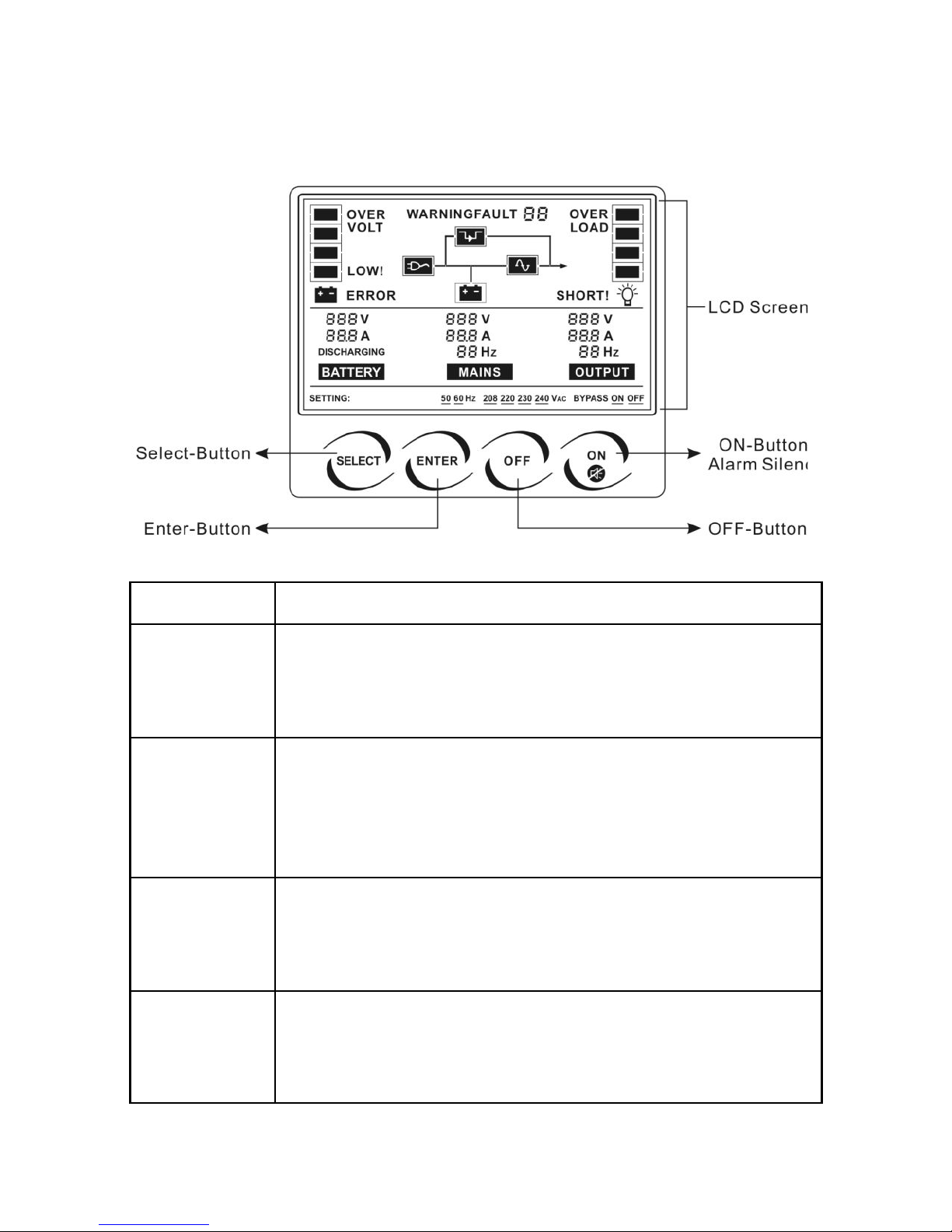
4. Display Panel
Switch
Function
ON-Button
By pressing the ON-Button, the UPS system is turned on.
If UPS is in normal mode it actives a battery test, it last 10sec.
If UPS has an alarm by pressing ON Button the acoustic alarm
can be deactivated.
OFF-Button
When mains power is normal, the UPS system switches to No
output or Bypass mode by pressing OFF-Button, and the
inverter is off. At this moment, if Bypass is enabled, then the
output sockets are supplied with voltage via the bypass if the
mains power is available.
Select-Button
If the UPS system is No output or Bypass mode, the output
voltage and frequency and Bypass disable/enable could be
selected by pressing Select-Button, and confirmed by pressing
Enter-Button.
Enter-Button
If the UPS system is No output or Bypass mode, the output
voltage and frequency and Bypass disable/enable could be
selected by pressing Select-Button, and confirmed by pressing
Enter-Button.

IV319 Rev.00
Data 2010-06-22 Pag. 17 di 118
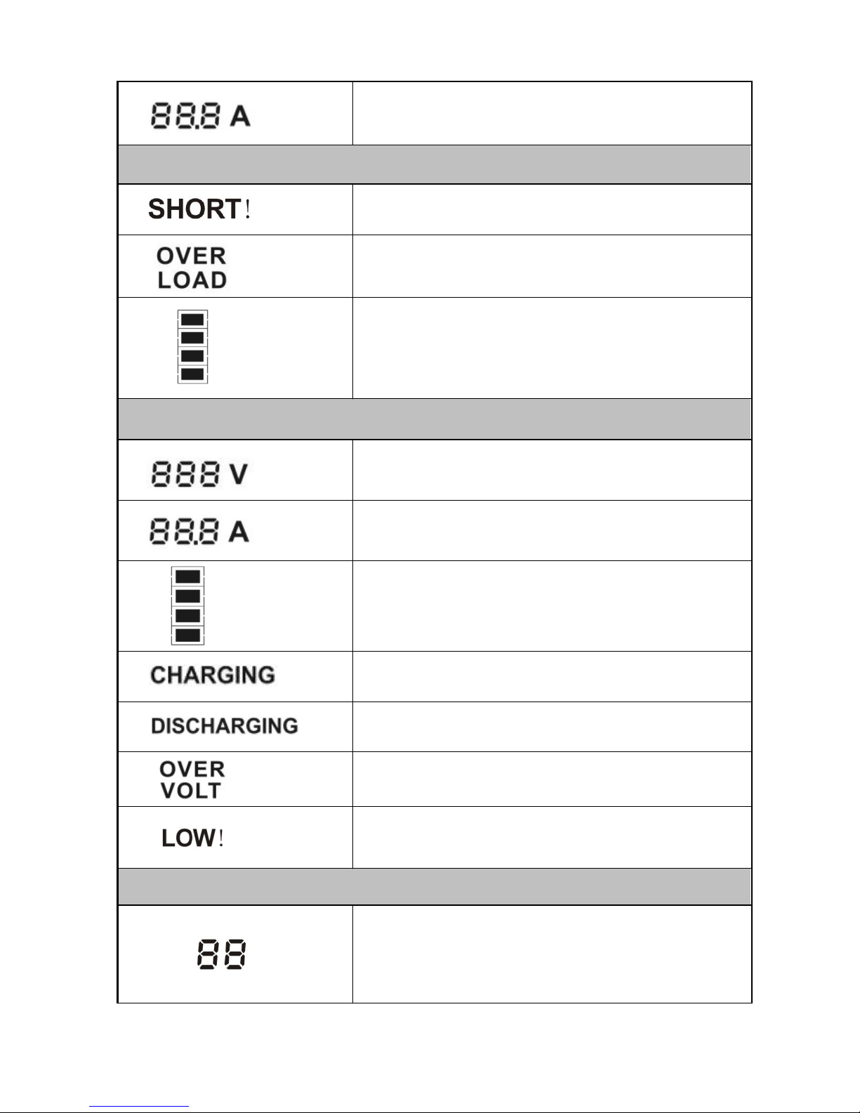
The LCD Display
Display
Function
Mains power Information *
Indicates the input voltage value
Indicates the frequency value ( Hz ) of input
voltage.
Indicates the input current value, with decimal
resolution.
Output Information
Indicates the UPS output voltage value
Indicates the frequency value ( Hz )of the UPS
output voltage
IV319 Rev.00
Data 2010-06-22 Pag. 18 di 118
Indicates the UPS output current value, with
decimal resolution
Load Information
Indicates the load or the UPS output is short and
the UPS would shut down
Indicates the load is over the SPEC range
Indicates the load percent, and the lowest grid
represent 30% load, the two low grids represent
60% load, the three low grids represent 90% load,
all the grids represent 100% load.
Battery Information
Indicates the battery voltage value, which could be
displayed from 0 to 999Vdc
Indicates the battery current value, which could be
displayed from 0 to 999A
Indicates the battery capacitance percent, and
every grid represent 25% capacitance. All the grids
represent 100% capacitance.
Indicates the charger of UPS is working and the
battery is being discharged.
Indicates the charger of UPS is not working.
Indicates the battery is over charged, and the UPS
would be switched to Battery mode
Indicates the battery is weak, and the UPS would
shut down soon
UPS status Information
Indicates the status of the UPS, Fault/Warning
code or the quantity of the parallel system could be
displayed, and the codes are illuminated in detail in
the following chapter
IV319 Rev.00
Data 2010-06-22 Pag. 19 di 118
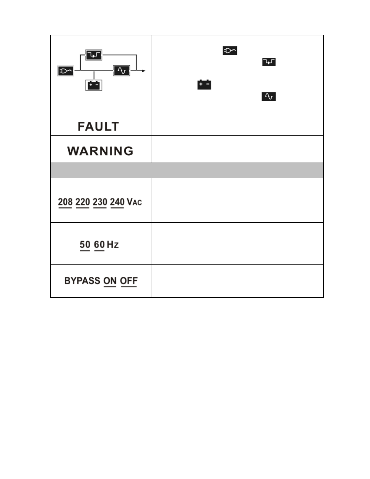
Indicates the operating mode of the UPS in
graphics mode. The will be displayed when
the mains power is normal; The will be
displayed when the UPS is working in bypass
mode; The will be displayed when the UPS
is working in battery mode; The will be
displayed when the inverter is working normal.
Indicates the UPS is working in fault mode.
Indicates some warnings occur which need be
attention.
UPS setting Information
One of these four values of the output nominal
voltage could be selected, it can be modify only
when the UPS is in No output or Bypass mode.
One of these two nominal frequency values of the
output voltage could be selected, it can be modify
only when the UPS is in No output or Bypass
mode.
Bypass disable or enable could be selected, it can
be modify only when the UPS is in No output or
Bypass mode.
* Notes: For 3/1 10K UPS, only the information of phase T will be shown;
while for 3/1 15K & 20K UPS, only the information of phase R will
be shown.

IV319 Rev.00
Data 2010-06-22 Pag. 20 di 118
5. Installation
5.1 Unpacking and Inspection
1) Unpack the packaging and check the package contents. The
shipping package contains:
ჀA UPS
ჀA user manual
ჀA SW CD+ RS232 communication cable
ჀA battery cable ( only on UPS 6 and 10K without battery )
2) Inspect the appearance of the UPS to see if there is any damage
during transportation. Do not turn on the unit and notify the carrier
and dealer immediately if there is any damage or lacking of some
parts.
5.2 Input and output power cords and protective earth
ground installation
1. Notes for installation
1) The UPS must be installed in a location with good ventilation,
far away from water, inflammable gas and corrosive agents.
2) Ensure the air vents on the front and rear of the UPS are not
blocked. Allow at least 0.20m of space on the front and rear of
the UPS.
3) Condensation to water drops may occur if the UPS is unpacked
in a very low temperature environment. In this case it is
necessary to wait until the UPS is fully dried inside out before
proceeding installation and use. Otherwise there are hazards of
electric shock.
The system may be installed and wired only by qualified
electricians in accordance with applicable safety regulations!
Table of contents
Other Siel UPS manuals

Siel
Siel SAFEPOWER S User manual

Siel
Siel 6kVA User manual

Siel
Siel SAFEPOWER S User manual

Siel
Siel SAFEPOWER SPM User manual

Siel
Siel SAFEPOWER S series User manual

Siel
Siel SAFEPOWER EVO HFT Guide

Siel
Siel SAFEPOWER S series User manual

Siel
Siel SAFEPOWER-EVO-HF Series User manual

Siel
Siel SAFEPOWER EVO-HF 200 Guide

Siel
Siel Safepower Evo 20 User manual


