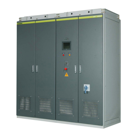
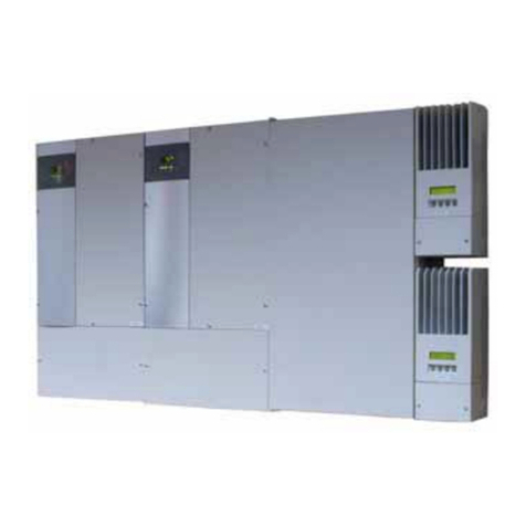
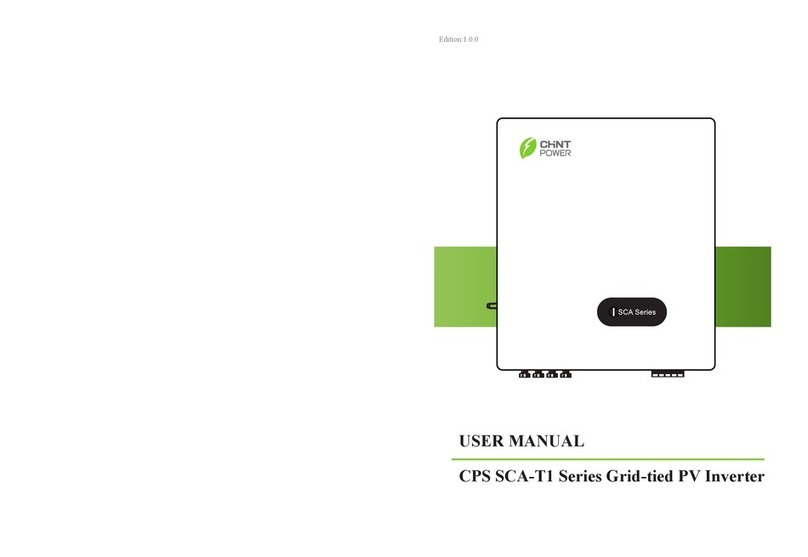
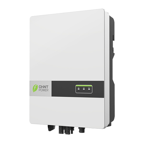
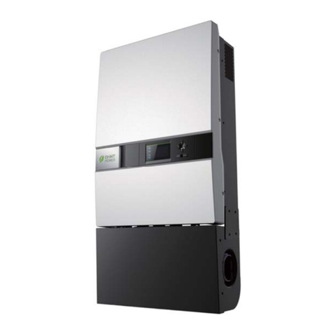
CHNT Power CPS SC500KTL User manual

CPS SC Series
Grid-tied PV Inverter
CPS SC500KTL
(CPS SC500KTL-H)
CPS SC250KTL-H
Installation and Operation Manual
SHANGHAI CHINT POWER SYSTEMS CO., LTD.

Table of Contents
Chapter 1 IMPORTANT SAFETY INSTRUCTIONS.........1
Chapter 2 Overview ........................................................4
2.1 Grid-tie PV system ················································ 4
2.2 Description of inverter types·································· 5
2.3 Inverter circuit structure········································· 5
2.4 Appearance ··························································· 7
2.4.1 Appearance description of CPS SC500KTL ... 7
2.4.2 Appearance description of CPS SC250KTL ... 8
Chapter 3 Installation......................................................9
3.1 Basic requirements················································ 9
3.2 Mechanical installation ·········································· 9
3.3 Electrical installation ············································ 16
3.3.1 DC connection ............................................. 18
3.3.2 AC and ground connection........................... 20
3.3.3 Communication connection.......................... 22
3.3.4 Dry contact and auxiliary power connection. 25
Chapter 4 Operation .....................................................27
4.1 Start-up and shut-down ······································· 27
4.1.1 Start-up......................................................... 27
4.1.2 Shut-down .................................................... 29
4.2 Operation mode··················································· 32
4.3 Grid connection and power generation················ 35
4.4 Fault shutdown ···················································· 36

4.5 Troubleshooting··················································· 37
Chapter 5 Human Machine Interface...........................44
5.1 Description of LCD display·································· 44
5.2 Operation state···················································· 45
5.3 Interface and menu functions ······························ 46
5.3.1 Interface types.............................................. 46
5.3.2 Main operation interface............................... 48
5.3.3 Operation information................................... 49
5.3.4 Present fault................................................. 50
5.3.5 History.......................................................... 50
5.3.6 System setup ............................................... 52
5.3.7 System protection parameter setup ............. 54
Chapter 6 Technical Data .............................................57
Chapter 7 Quality Assurance.......................................63
7.1 Warranty······························································ 63
7.2 Disclaimer ··························································· 63
7.3 Quality clause (Warranty clause)························· 63

Chapter 1 IMPORTANT SAFETY INSTRUCTIONS
1
Chapter 1 IMPORTANT SAFETY INSTRUCTIONS
(SAVE THESE INSTRUCTIONS)
Please read this manual carefully before installation. The
warranty will be invalid automatically if the user does not
follow this manual during installation and operation resulting
in damage to the equipment.
ELECTRIC SHOCK HAZARD:
All operations and wiring should be performed by qualified
technical personnel!
Disconnect the inverter from PV assemblies and the Grid
before the maintenance and operation of the equipment.
At the same time, make sure that equipment is grounded
properly!
WARNING:
1. When the connected PV module is exposed to the
sunlight, it generates DC voltage and charges the DC bus
capacitors of the inverter. Electric charges are still stored in
the capacitors even the input of the PV inverter is turned off.
Therefore, equipment shall not be maintained or operated
until 60 minutes after all inputs are cut off or the “De-energy”

Chapter 1 IMPORTANT SAFETY INSTRUCTIONS
2
command is carried out successfully through LCD button
operations.
2. This inverter is specially designed to connect AC power to
the public grid. Do not connect the AC output of this
equipment directly to private AC power equipments.
3. If the DC circuit breaker is tripped because of malfunction,
it is prohibited to turn on the DC circuit breaker directly.
System reset program must be executed and then turn on
the DC circuit breaker according to the indication on the
LCD.
4. Before opening the inverter for maintenance, shut down
the inverter through LCD operation. Turn off the DC circuit
breaker, execute the De-energy program and then turn off
the AC circuit breaker. The inverter should not be maintained
until the voltmeter shows that there is no electric charge left
in the DC bus capacitor!
CAUTION:
1. Pay attention to inverters’ center of gravity and
recommend users to use forklifts to carry.
2. The command of De-energy will be ineffective if the
inverter is being energized. Wait and execute the command
until the process of De-energy is completed.
3. If software needs to be updated, AC and DC circuit
breakers must be turned off and the auxiliary power mode

Chapter 1 IMPORTANT SAFETY INSTRUCTIONS
3
should be switched to outside power supply.
HIGH TEMPERATURE:
Do not touch the metal surfaces of the radiator and inverter
during the operation of the inverter!

Chapter 2 Overview
4
Chapter 2 Overview
2.1 Grid-tie PV system
CPS SC500KTL (CPS SC500KTL-H), CPS
SC250KTL-H grid connection photovoltaic inverters are
mainly applied to power station systems. Normally, the
system consists of PV modules, DC power distribution unit,
grid connection inverter and AC power distribution unit
(Figure 2-1). Solar energy is converted to direct current
through PV modules. The direct current is then converted to
alternative current with the same frequency and phase as
the grid through grid connection inverter and fed to the grid
after voltage stepped up by transformer.
Figure 2-1 Grid connection photovoltaic power generation system

Chapter 2 Overview 5
2.2 Description of inverter types
CPS SC500KTL (CPS SC500KTL-H), CPS 250KTL-H
are the two kinds of grid-tie PV inverter with the power of
500KW and 250KW without transformer for large-scale
power stations. The suffix “H” means that The Maximum DC
input Voltage of CPS SC500KTL-H and CPS 250KTL-H is
1000V while the Maximum DC input Voltage of CPS
SC500KTL is 880V.
In terms of the suffix after the “/”, to take CPS
SC500KTL/CN as an example, this type of inverter passes
the Golden Sun certification. CPS 250KTL-H is the inverter
that passes the TUV certification. Detailed information can
be inquired from our CPS salesmen.
*Because the appearance and dimensions as well as
the basic internal structure of CPS SC500KTL-H and CPS
SC500KTL share the same, CPS SC500KTL will be taken as
representative in the following instruction.
2.3 Inverter circuit structure
The basic schematic diagram of CPS SC500KTL
inverter is shown in Figure 2-2. CPS SC500KTL inverter
consists of two independent 250KW modules of input and
output parallel connections. The DC voltage output by PV
modules is supplied to the two 250KW inverters combined
together by short circuit at the input terminal. Each 250KW
inverter converts the DC voltage to 3-phase AC voltage
(3*270VAC) after the DC current passes through DC circuit

Chapter 2 Overview
6
breaker, DC EMI filter, inverter unit and then remove the high
frequency component with the output sine wave filter. The
two strings of current will be connected in parallel after going
through Level 1 AC circuit breaker and be transferred to AC
EMI circuit and breaker, then finally be fed to the power grid.
The basic schematic diagram of CPS SC250KTL-H inverter
is shown in Figure 2-3.
Figure 2-2 Schematic diagram of CPS SC500KTL
Figure 2-3 Schematic diagram of CPS SC250KTL-H

Chapter 2 Overview 7
2.4 Appearance
2.4.1 Appearance description of CPS SC500KTL
Figure 2-4 Appearance sketch of CPS SC500KTL
Description of main components (Figure 2-4):
1、Operating handle of DC circuit breaker
2、Operating handle of AC circuit breaker
3、LCD display panel and operation buttons
4、Emergency stop button
5、Logo of Chint Power System Co. Ltd
6、Door lock
A: Cabinet 1 for DC input invertion and controlling
B: Cabinet 2 for DC input invertion and controlling
C: AC output cabinet

Chapter 2 Overview
8
2.4.2 Appearance description of CPS SC250KTL
Figure 2-5 Appearance sketch of CPS SC250KTL-H
Description of main components (Figure 2-5):
1、Operating handle of DC circuit breaker
2、Operating handle of AC circuit breaker
3、LCD display panel and operation buttons
4、Emergency stop button
5、Logo of Chint Power System Co. Ltd
6、Door lock
A: Cabinet 1 for DC input invertion and controlling
B: AC output cabinet

Chapter3 Installation
9
Chapter 3 Installation
3.1 Basic requirements
The protection level of CPS SC500KTL, CPS
SC250KTL-H photovoltaic inverter is IP20. Please DON’T
install the equipment in a humid environment.
9Check and make sure that the ambient temperature
of the installation environment is -25 °C ~+60°C;
9Make sure that the public power grid voltage is
215~310Vac (Default value is 243~297Vac and the
parameter can be adjusted on the LCD display panel
according to the actual grid voltage.) and the grid
frequency is 50Hz;
9Permission of grid connection has been granted by
the local electric power authority;
9Installation personnel must be qualified electricians
or people who have received professional training;
9Sufficient convection space;
9Away from flammable and explosive substances
3.2 Mechanical installation
(1) Dimensions
Dimensions of CPS SC500KTL grid-tie PV inverter are
shown in Figure 3-1.

Chapter 3 Installation
10
Figure 3-1 Dimensions of CPS SC500KTL
*Notice: The dimensions in Figure 3-1 do NOT include
the operating handles. The overall dimensions including the
operating handles are 2800(L)x855(D)x2100(H)mm.
Dimensions of CPS SC250KTL-H grid-tie PV inverter
are shown in Figure 3-2.
Figure 3-2 Dimensions of CPS SC250KTL-H

Chapter3 Installation
11
*Notice: The dimensions in Figure 3-1 do NOT include
the operating handles. The overall dimensions including the
operating handles are 2800(L)x855(D)x2100(H)mm.
(2) Requirements of inverter installation:
a: The installation dimensions of CPS SC500KTL are
shown in Figure 3-3.
162
175
36
26728
80
54
72 72
12-∮16X30
2800
1000 928 800
80
780
26
26
Figure 3-3 Installation dimensions of CPS SC500KTL
b: The installation dimensions of CPS SC250KTL-H are
shown in Figure 3-4.
928 526
26
6-∮16x30
2-∮16
81
728
1600
175
162
80
54
74
36
780
26
26
Figure 3-4 Installation dimensions of CPS SC250KTL-H

Chapter 3 Installation
12
Notes:
Front door: A 1000mm space should be reserved to
ensure that the front door can be opened and closed freely.
Back: A 800mm space should be reserved for
maintenance.
Top: A 600mm space should be reserved for sufficient
convection.
The weight of CPS SC500KTL is approximately 2000kg.
and the weight of CPS SC250KTL-H is about 1100Kg.
Please make sure that the mounting place can bear the
weight.
(3)Two approaches are recommended to lift the
machine, i.e. lifting with a crane or a forklift:

Chapter3 Installation
13
A: Lifting CPS SC500KTL with a crane:
Put 4 sling ropes through the four eye bolts on the top of
inverter(each no shorter than 1 meter).Then lift the machine
slowly to the appropriate location for installation with the
crane (shown in Figure 3-5).
Center of gravity:
1200-1300mm to the left edge
About 500mm to the front door
Figure 3-5 Diagram of lifting CPS SC500KTL with a crane
B: Lifting CPS SC250KTL-H with a crane:
Put 4 sling ropes through the four eye bolts on the top of
inverter(each no shorter than 1 meter).Then lift the machine
slowly to the appropriate location for installation with the
crane (shown in Figure 3-6).

Chapter 3 Installation
14
Center of gravity:
670-700mm to the left edge
About 500mm to the front door
Figure 3-6 Diagram of lifting CPS SC250KTL-H with a crane
Because the center of gravity of both of the equipments
is not located at the middle position, thus two long and two
short sling ropes are required to lift them. The recommended
length of rope is shown in Table 3-1.
Table 3-1 Unit (mm)
Short sling ropes 1000 1500 2000
Long sling ropes 1200 1650 2120
*Note 1: The included angle (acute angle) between the
sling rope and the top plate should be more than 45 degree.
Besides, try to keep the lifting hook and inverters’ center of
gravity on the same perpendicular line.

Chapter3 Installation
15
Caution:
Pay attention to inverters’ center of gravity and
recommend users to use forklifts to carry.
Lifting with a forklift:
Insert the fork at the bottom place of the machine from
the back and lift it to the appropriate location for installation.
The position for placing the arms of forklift is shown in Figure
3-7 and 3-8.
Figure 3-7 Diagram of lifting CPS SC500KTL with a forklift

Chapter 3 Installation
16
Figure 3-8 Diagram of lifting CPS SC250KTL-H with a forklift
*Note: Please try to carry the inverter from its back when
using a forklift. If it is necessary to carry it from its front,
buffer material needs to be placed on the front door to
prevent the inverter from being damaged by the forklift.
3.3 Electrical installation
Open the front door of the machine. Proceed as shown
in Figure 3-9.
1. Turn the operating handle of DC circuit breaker
anti-clockwise to horizontal position.
2. Unlock the door with the door key, turn the door knob
anti-clockwise to horizontal position and then pull the knob to
open the front door of Invertion cabinet 1.
3. Repeat step 1 and 2 to open the front door of

Chapter3 Installation
17
Invertion cabinet 2. (Note: This step is NOT needed for CPS
SC250KTL-H because it has only one invertion cabinet.)
4. Turn the operating handle of AC circuit breaker
anti-clockwise to horizontal position.
5. Unlock the door with the door key, turn the door knob
anti-clockwise to horizontal position and then pull the knob to
open the front door of AC output cabinet.
Figure 3-9 Diagram of opening front doors
6. After opening the front door, remove the protective
and transparent Plexiglas covers at the bottom of the
machine and connect the external cables to the inverter, as
shown in Figure 3-10.
1 3
2 54
This manual suits for next models
2
Table of contents
Other CHNT Power Inverter manuals
Popular Inverter manuals by other brands

Airpax Dimensions
Airpax Dimensions MIL-24/2600Q owner's manual

Westerbeke
Westerbeke Series 11 BTD Specifications

Miller
Miller Trailblazer 302 Diesel owner's manual

Kaco
Kaco blueplanet 3.0 TL3 M2 WM OD IIG0 operating instructions

XSY
XSY AT Series manual

Sol
Sol GreenWay GRNWY-50 Installation and owner's manual