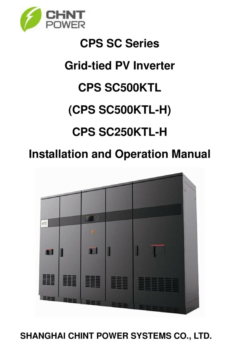
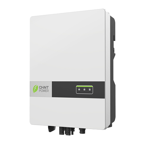
CHNT Power CPS SC Series User manual

Chint Power Systems America
700 International Pkwy, Suite 102, Richardson, TX 75081
SHANGHAI CHINT POWER SYSTEMS CO., LTD. All rights reserved.
Specifications and designs included in this datasheet are subject to change without notice.
CHINT POWER 2012/08-MKT
η
3DF:
9
9
9
9
9
20kW Grid-tied PV Inverter for North America
Efficiency Curve
MPPT VOLTAGE
Broad Adaptability
High Reliability
High Efficiency
Datasheet
Dimensions
The CPS SC20KTL-DO/US-480 grid-tied PV inverter is a tranformerless,
three phase product designed for the North America market in
compliance with UL and CSA standards. Patented 3-level control
algorithm and thermal design provide 97.3% maximum efficiency.
CPS SC20KTL-DO/US-480 features small size, light weight and high
power density. Multi flexible mounting modes make installation and
maintenance easy and quick. The enclosure of the inverter is rated
NEMA 3R (IP65) for general purpose outdoor applications. Enhanced
DSP control, comprehensive protection functions and advanced thermal
design enable a high reliability product with optional warranties up to 20
years.
Maximum efficiency of 97.3%, CEC efficiency of 96.5%
3-level technology and enhanced control mechanism to
achieve high efficiency over wide load range
2 MPP trackers to achieve higher system efficiency
Transformerless design
High speed and precise MPPT algorithm
Design for reliability
Comprehensive protection functions
Enhanced DSP system
Advanced thermal design, with variable speed fans
Anti-Islanding protection
Ground-fault detection and interruption circuit
Redundant controller for system protection
NEMA 3R (IP65), outdoor application
Multi mounting modes, quick installation and
easy maintenance
High altitude application
Integrated DC (+, -) and AC disconnect
Light weight, compact design for commercial rooftops
Wide MPPT range enables flexible stringing
Standard warranty: 5 years, extention up to 20 years

Model Name CPS SC20KTL-DO/US-480
Max. PV Power 27kW
Nominal DC Input Power 21kW
Max. DC Input Voltage 600Vdc
Operating DC Input Voltage Range 260-580Vdc
Start-up DC Input Voltage / Power 300V / 200W
Nominal DC Input Voltage 500Vdc
Number of MPP Trackers 2
MPPT Voltage Range 300-550Vdc
Max. Input Current 35Ax2
Number of DC Inputs and Fuses 4 conductors with fuse per each of two MPPT inputs
DC Disconnection Type Switch
Rated AC Output Power 20kW
Max. AC Output Power 20kW
Rated Output Voltage 480Vac
Output Voltage Range 422-528Vac
Grid Connection Type 3I/ N / PE
Max AC Output Current 27.3A
Rated Output Frequency 60Hz
Output Frequency Range 59.3-60.5Hz
Power Factor >0.99
Current THD <3%
AC Disconnection Type Switch
Topology Transformerless
Max. Efficiency 97.3%
CEC Efficiency 96.5%
Stand-by / Night Consumption <20W / <2W
Protection Degree NEMA 3R
Cooling Variable speed cooling fans
Operating Temperature Range -13°F to +140°F / - 25°C to +60°C (derating from +55°C / +131°F)
Operating Humidity 0-95%, non-condensing
Operating Altitude 6562ft / 2000m (derating from 4921ft / 1500m)
Display LCD + LED
Communication RS485
Dimensions (WxHxD) 21.4x41.6x8.5in / 544x1058x215mm
Weight 132lbs / 63kg
Safety and EMC Standard UL1741:2010, CSA-C22.2 NO.107.1-01, IEEE1547; FCC PART15
Grid Standard IEEE1547: 2003, IEEE1547.1: 2005
Display and Communication
Mechanical Data
Safety
DC Input
AC Output
System
Environment
Technical Data
Information furnished is believed to be accurate and reliable. However, Chint Power Systems assumes no responsibility for the consequences of use of
such information nor for any infringement of patents or other rights of third parties which may result from its use. No license is granted by implication or
otherwise under any patent or parent rights of Chint Power Systems. Specifications mentioned in this publication are subject to change without notice. This
publication supersedes and replaces all information previously supplied.

CPS SC Series
Grid-tied PV Inverter
CPS SC20KTL-DO/US-480
Installation and Operation Manual
CHINT POWER SYSTEMS AMERICA CO., LTD.

Table of Contents
Before You Start…..........................................................1
Chapter 1 IMPORTANT SAFETY INSTRUCTIONS......2
Chapter 2 Overview .....................................................4
2.1 Inverter for grid-tied PV systems ........................4
2.2 Product type description.....................................4
2.3 Product features .................................................5
2.4 Circuit structure design.......................................6
2.5 Appearance description......................................6
Chapter 3 Installation...................................................8
3.1 Basic requirements.............................................9
3.2 Mechanical installation .......................................10
3.3 Electrical installation...........................................18
3.3.1 DC connection ...........................................18
3.3.2 AC and ground connection.........................24
3.3.3 Communication connection........................26
Chapter 4 Operation ....................................................29
4.1 Start-up and shut-down ......................................29
4.1.1 Start-up ......................................................29
4.1.2 Shut-down..................................................29
4.2 Operation mode..................................................30
4.3 Grid connection and power generation...............32

4.4 Fault shutdown...................................................38
Chapter 5 Human Machine Interface..........................38
5.1 Description of LCD panel ...................................38
5.2 Operation state...................................................39
5.3 Interface and menu functions .............................40
5.3.1 Interface types ...........................................40
5.3.2 Main operation interface ............................42
5.3.3 Operation information ................................43
5.3.4 Present fault...............................................44
5.3.5 History........................................................45
5.3.6 System setup .............................................46
5.3.7 System protection parameter setup ...........48
Chapter 6 Service and Maintenance ..........................51
6.1 Disassembling of fan tray assembly...................51
6.2 Restoring of fan tray assembly...........................53
Chapter 7 Technical Data ............................................58
Chapter 8 Limited Warranty........................................61

1
Before You Start…
This manual contains important information regarding
installation and safe operation of this unit. Be sure to read
this manual carefully before using.
Thanks for choosing this Grid-tied PV Inverter (referred to in
this manual as “PV Inverter”, or simply “Inverter”). This Grid
PV Inverter is a highly reliable product due to its innovative
design and perfect quality control. Such an Inverter is used
in high demand, grid-tied PV systems.
If you encounter any problems during installation or
operation of this unit, first check this manual before
contacting your local dealer or supplier. Instructions inside
this manual will help you solve most installation and
operation difficulties.
Please keep this manual on hand for quick reference.

Chapter 1 IMPORTANT SAFETY INSTRUCTIONS
2
Chapter 1 IMPORTANT SAFETY INSTRUCTIONS
(SAVE THESE INSTRUCTIONS)
Please read this manual carefully before installation. CPS
reserves the right not to guarantee the quality for equipment
damage if the user fails to install the equipment as per the
instructions in this manual.
ELECTRIC SHOCK HAZARD:
A
ll operations and wiring should be performed by qualified
technical personnel.
Disconnect the inverter from PV modules and the Power
Grid before the maintenance and operation of the
equipment.
ELECTRIC SHOCK HAZARD:
Before opening the inverter, hazardous high voltage and
energy inside the equipment must be discharged and the
DC conductors of PV modules should be grounded.
Do not remove cover until 10 minutes after disconnecting all
sources of power supply.
WARNING:
This inverter is specially designed to connect AC power to
the public grid. Do not connect the AC output of this
equipment directly to private AC power equipments.
WARNING:
Do not install the inverter under direct sunlight exposure to

Chapter 1 IMPORTANT SAFETY INSTRUCTIONS 3
avoid reducing conversion efficiency due to excessively high
internal temperature of the machine.
CAUTION:
Steel conduits as the cable protector need to be prepared by
the customers before installation.
HIGH TEMPERATURE:
A
lthough designed to meet international safety standards,
the PV-Inverter can become hot during operation. Do not
touch the heat sink or peripheral surfaces during or shortly
after operation.
HIGH TEMPERATURE:
The inverter and peripherals can be hot after operation.
Maintenance shall be performed 15 minutes after the DC
and AC power are both switched off.

Chapter 2 Overview
4
Chapter 2 Overview
2.1 Inverter for grid-tied PV systems
CPS SC20KTL-DO/US-480 inverter can be applied to
various commercial rooftop systems and distributed power
station systems. Normally, the system mainly consists of PV
modules, DC power distribution equipments, PV inverter and
AC power distribution equipments (Figure 2-1). The inverter
converts the DC energy from PV modules to the AC energy
that is compatible with the public grid. The AC energy can be
used directly by the local load, or it can be sold to your
energy provider.
Figure 2-1 Grid-tied PV system
2.2 Product type description
CPS SC20KTL-DO/US-480 is a two-MPPT PV inverter
integrated with the DC and AC switches for indoor and
outdoor application. The suffix “US” means that this model of
inverter passes the UL certification and is specialized for the
American market.

Chapter 2 Overview 5
2.3 Product features
CPS SC20KTL-DO/US-480 inverter incorporates the
advanced 3-level and MOSFET paralleled with IGBT
technology to minimize the energy loss.
The two-MPPT design has the benefit of increasing the
power generating efficiency of the whole PV system. The
inverter has 2 MPPTs, so a separate array can be controlled
by an independent Maximum Power Point Tracking (MPPT)
control circuit. This means that the two arrays can be
installed in different positions and orientations.
The transformerless design of inverter with the benefit
of small size, light weight and high power density, provides
the best cost performance for the whole PV system.
The inverter is available for both indoor and outdoor
applications due to its NEMA 3R (IP65) protection class
enclosure.
The integrated DC and AC switches make the
maintenance more flexible and safer. Besides, the inverter
has the function to support one or two independent MPPTs
input to improve the system efficiency. Meanwhile, the
inverter can automatically identify the connection way
between PV modules due to its excellent self-adaption
ability.

Chapter 2 Overview
6
2.4 Circuit structure design
The basic schematic diagram of CPS
SC20KTL-DO/US-480 is shown in Figure 2-2. The input DC
passes through lightning-proof circuit, DC EMI filter, and the
boost circuit to achieve maximum power tracking and boost
up voltages. The inverter converts the DC energy to 3-phase
AC energy. The high frequency components of AC voltage
are removed with a line filter. Then the 3-phase AC energy is
sent through two-stage relays and EMI filter for outputting.
Figure 2-2 Schematic diagram of CPS SC20KTL-DO/US-480
2.5 Appearance description
Figure 2-3 Appearance sketch of CPS SC20KTL-DO/US-480

Chapter 2 Overview 7
Description of main items of CPS
SC20KTL-DO/US-480 (shown in Figure 2-3):
1、LCD key buttons: operate the functions and change
settings of inverter
2、LCD display: indicates data
3、LED indicator lights: indicate the status of inverter
4、DC input (4), AC output & ground terminals (1) and
signal port (1) from left to right
5、DC switch: control the DC power on and off
6、AC switch: control the AC power on and off
7、Main housing
8、Wiring box

Chapter 3 Installation
8
Chapter 3 Installation
Below is the installation instruction of the inverter. Please
read carefully and install the product step-by-step.
1. CPS SC20KTL-DO/US-480
Check and make sure that the following items are
included in the package before installation, as shown in
Table 3-1.
Table 3-1 Main items
Item Q’ty Note
(1) CPS
SC20KTL-DO/US-480
Grid-tied PV inverter
1 Grid-tied PV inverter
(2) Mounting bracket 1
upon which Inverter is
hung and mounted onto a
wall
(3) User manual 1 Installation and operation
manual
(4) Warranty service
card 1 for maintenance and
repair
(5) Accessory kit 1 contains all necessary
accessories
The (5) Accessory kit contains items listed below:
Table 3-2 Accessories
Item Q’ty Purpose
M (8×25L) expansion 8 pairs for bracket installation (2

Chapter 3 Installation
9
bolts & nuts pairs for backup use)
M5 nut 2for grounding wire (1 nut
for backup use)
Ring terminal 1 for grounding wire
Cord end terminals 20
16 for input wires, 3 for
output wires, 1 for neutral
wire (optional)
RJ45 connecters 4 for communication cables
Red wire 1 for inverter with 1 MPPT
working alone
Black wire 1 for inverter with 1 MPPT
working alone
3.1 Basic requirements
9Check and make sure that the ambient temperature of
the installation location is -25°C ~ +60°C;
9Make sure that the power grid voltage is within normal
range;
9Permission of grid connection has been granted by the
local electric power authority;
9Installation personnel must be qualified electricians or
people who have received professional training;
WARNING:
Do not install the inverter under direct sunlight exposure to
avoid reducing conversion efficiency caused by excessively
high internal temperature of the machine.

Chapter 3 Installation
10
9Sufficient convection space;
9Away from flammable and explosive substances.
3.2 Mechanical installation
(1) Dimensions
The dimensions of CPS SC20KTL-DO/US-480 inverter
are shown in Figure 3-1.
Figure 3-1 Dimensions of CPS SC20KTL-DO/US-480
(2) Check whether the place to mount the inverter is
appropriate:
(a) It’s better to mount the inverter in a vertical
position.
(b) If the inverter cannot be mounted vertically, it is
allowed to be tilted backward by Max. 15°.

Chapter 3 Installation
11
(c) Do NOT mount the inverter forwards.
(d) Do NOT mount the inverter in a horizontal position.
(e) Do NOT mount the inverter upside down.
(a) (b)
(c) (d) (e)
Figure 3-2 Mounting the inverter properly
(3) Space required for inverter mounting on the wall (as
shown in Figure 3-3)
The distances between the inverter and the surrounding

Chapter 3 Installation
12
objects should meet the following conditions: two sides from
the walls ≥11.81 inches; top distance ≥11.81 inches; bottom
distance ≥23.62 inches; the minimum spacing between two
inverters in parallel ≥11.81 inches.
Figure 3-3 Inverter mounting dimensions
(3) Secure the bracket with bolts through the mounting
holes and install the inverter:
(a) Mark the 6 bolt holes for mounting the bracket as
shown in Figure 3-4;

Chapter 3 Installation
13
Figure 3-4 Bracket mounting dimensions
(b) Drill holes at the marked positions with a diameter
of 0.4 inch drill and put the 6 M8*25 expansion
bolts into the holes;
(c) Take the mounting bracket out of the package and
secure the bracket on the wall with the 6 nuts in
pair as shown in Figure 3-5;

Chapter 3 Installation
14
Figure 3-5 Positions of bolt holes on the bracket
(d) Screw off the bolts and remove the two panels on
both sides of the inverter as shown in Figure 3-6;
Figure 3-6 Removal of panels before mounting inverter
(e) Two people grab at the position on each side, lift
up the inverter and then hang it on the bracket
(Figure 3-7a~e). Make sure the inverter is
securely hooked on the bracket;

Chapter 3 Installation
15
Figure 3-7a Mounting inverter on the bracket
Figure 3-7b Mounting inverter on the bracket
Hand Grab
This manual suits for next models
2
Table of contents
Other CHNT Power Inverter manuals
Popular Inverter manuals by other brands
SMA
SMA Powerline Kit Brief Instruction

Hon Turing
Hon Turing HT-T-S1000-12 introduction

Mission Critical
Mission Critical Xantrex Freedom SW-RVC owner's guide

Dometic
Dometic SI 1500 user manual
Dometic
Dometic BUTTNER MT 600 SI-N Installation and operating manual
SMA
SMA Sunny Boy SB 5000US installation guide

