Choice MD300I2 User manual

Pulse Oximeter
Instruction
Manual
Ver.1.0

V1.0I2 PULSE OXIMETER OPERATOR'S MANUAL
1
Contents
CHAPTER 1 Introduction ...........................................................................3
1.1 Brief Introduction........................................................................3
1.2 Safety Information ......................................................................3
1.3 Intended Use...............................................................................6
1.4 Electromagnetic Interference.....................................................6
1.5 Equipment Classification ...........................................................6
CHAPTER 2 General Descriptions.............................................................6
2.1 Front Panel & Displaying............................................................7
2.2 Rear Panel.................................................................................10
2.3 Product Features ......................................................................10
CHAPTER 3 Install the Batteries and the Sensor.................................... 11
3.1 Install the Batteries................................................................... 11
3.2 Install the Sensor......................................................................12
CHAPTER 4 Setting ID, Date and Time....................................................12
4.1 Date & Time Setting..................................................................13
4.2 ID Number Setting.....................................................................14
CHAPTER 5 Take a Measurement............................................................15
CHAPTER 6 Other Settings......................................................................17
6.1 Alarm Setting ............................................................................17
6.2 Sound Setting ...........................................................................21
6.3 Backlight Setup.........................................................................21
6.4 Data Review ..............................................................................22

V1.0I2 PULSE OXIMETER OPERATOR'S MANUAL
2
6.5 Other Information......................................................................22
CHAPTER 7 Maintenance and Repair......................................................23
7.1 Maintenance..............................................................................23
7.2 Calibration and Verification......................................................24
7.3 Trouble Shooting ......................................................................25
7.4 Warranty and Repair.................................................................25
7.5 Storage and Transportation......................................................27
APPENDIX A Specifications.....................................................................28
APPENDIX B Declaration .........................................................................30

CHAPTER 1 Introduction
1.1 Brief Introduction
Thank you for purchasing the handheld pulse oximeter. The main functions of
the device include SpO2and PR measure, visual and audio alarm, sensor off
alarm, data storage and replay etc. Please read the operator's manual
carefully before using it.
Note: The illustrations used in this manual may differ slightly from the
appearance of the actual product.
1.2 Safety Information
Conception of Warning, Precaution and Notice
The Warning, precaution and Notice in this document are special information
in favor of users operation.
★Warning
Indicate that maybe some potential hurt or damage to patients.
★Precaution
Make user take a serious attitude toward the incorrect operation, which are
likely to incur some life-threatening incidents.
★Notice
Serve as a pivotal notice to avoid preventable incidents during application of
this equipment.
Warnings:
The handheld pulse oximeter should be confined to sophisticated operator
exclusively. Prior to application, we strongly suggest you should follow
instructions listed in this document, or any wrong-doing operation which
causes serious damage will take full responsibility for this. Our company will
assume no warranty for using this equipment improperly.
Do not close to liable flammable matters, spark in case of unexpected
explosion.
Do not apply this equipment at such environment as magnetic resonance
imaging (MR or MRI) equipment which is the source of some electric noise
to influence the accuracy of this equipment and following treatment.
Make sure to apply this equipment for medial scope, and measurement
results only serve as a reference for any relevant treatment.
Please cautiously use this equipment for long time, and It is necessary for
you to protect yourself from avoidable injury.

V1.0I2 PULSE OXIMETER OPERATOR'SMANUAL
4
When placing sensor in right place, please abide by work instructions
strictly, for example do not extend tape or fix it too tightly.
When beginning to measure associated body features please follow the
doctor’s counseling.
When link this equipment to other peripherals, make sure you are
sophisticated operator to handle this device. Any peripherals should be in
the light of protocol of IEC 950 and IEC 601-1-1. Any input/output device
should be following the protocol of IEC 601-1-1.
Please strictly follow the sensor application instructions, considering the
sensor is a sensitive device.
The malfunction of sensor may cause inaccurate data which serve as a
foundation to treat patients, so please make sure to pay more attention to
the sensor and inspect it frequently.
The worn-out data cables may cause inaccurate data and be used as a
reference to treat patient, so please pay attention to data cable and check it
frequently.
The disposable peripheral should not be repeatedly used.
Precautions
Rinsing the sensors with ethylene oxide solution may have adverse
influence on the machine, Apart from this, the sensor should not be
autoclaved or submerged.
This device is intended for use by persons trained in professional health
care. The operator must be thoroughly familiar with the information in this
manual before using the device.
Unplug the sensor from the monitor before cleaning or disinfecting to avoid
the damage to the device and user.
Alarm must be set up according to different situation of individual patient.
Make sure that chime sound can be activated when alarm function begin to
work.
Notices
Application of this device may influence the measuring accuracy in the
background of electromagnetic areas such as electro-surgery environment.
Operation of this device may be adversely affected in the presence of
computed tomography (CT) equipment. Use only the appointed sensors.
Use of sensors not intended for use with this device may cause inaccurate

V1.0I2 PULSE OXIMETER OPERATOR'SMANUAL
5
readings. Pay more attention to the application when applying this device
under the situation of computed tomography (CT) environment.
SpO2measurements may be adversely affected in the presence of high
ambient light. Shield the sensor area (with a surgical towel, for example) if
necessary.
Dyes introduced into the bloodstream, such as methylene blue,
indocyanine green, indigo carmine, and fluorescein, may adversely affect
the accuracy of the SpO2reading.
Any condition that restricts blood flow, such as use of a blood pressure cuff
or extremes in systemic vascular resistance, may cause a failure to
determine accurate pulse rate and SpO2readings.
Remove fingernail polish or artificial fingernails before applying SpO2
sensors. Fingernail polish or artificial fingernails may lead to inaccurate
SpO2readings.
SpO2average is the number of pulse beats over which the SpO2value is
averaged; pulse average is the number of seconds over which the pulse
value is averaged.
Hazards arising from software errors have been minimized. Hazard
analysis conforms to meet ISO14971: 2000 and EN60601-1-4: 1996.
Significant levels of dysfunctional hemoglobins, such as
carboxy-hemoglobin or methemoglobin, will affect of the accuracy of the
SpO2measurement.
Optical cross-talk can occur when two or more sensors are located in
adjoining area. It can be eliminated by covering each site with opaque
material. Optical cross-talk may adversely affect the accuracy of the SpO2
readings.
Change new batteries in time, when the power low indicator appears. As,
the readings will influenced when the power is low.
Obstructions or dirt on the sensor’s red light or detector may cause a
sensor failure. Make sure there are no obstructions and the sensor is clean.
For routine equipment maintenance, please refer to the service procedures
at the associated section as indicated in the manual.
As to the other concerns for attention, please carefully look through the
specific chapter in this instruction.

V1.0I2 PULSE OXIMETER OPERATOR'SMANUAL
6
1.3 Intended Use
The purpose and function of the handheld pulse oximeter is to indicate
measure and display the functional oxygen saturation of arterial hemoglobin
(SpO2) and pulse rate for adults and pediatric patients in hospital, ambulatory,
home, and EMS (emergency medical service) environments. The pulse
oximeter is intended for spot-checking these levels and not indicated for
continuous monitoring. It can assist the clinician diagnostically by quickly
displaying the patient’s SpO2% and pulse rate and can additionally store 72
hours of data.
1.4 Electromagnetic Interference
This oximeter is designed and tested in compliance with the EMC standard,
complying with the international standard for the EMC of the electronic
medical device - IEC 60601-1-2. However, because of the proliferation of radio
frequency transmitting equipment and other sources of electrical noise in the
health-care and home environments (e.g. cellular phones, mobile two-way
radios, electrical appliances) it is possible that high levels of such interference
due to close proximity or strength of a source, may result in disruption of
performance of this device.
This apparatus complies with the IEC 60601-1-2 international standard. The
requirements of this international standard are: CISPR11, GROP1, and
CLASS B
1.5 Equipment Classification
CHAPTER 2 General Descriptions
The handheld pulse oximeter adopts 1.5 inch CSTN screen. It can display the
SpO2,pulse rate value and all kinds of parameters, such as time, ID number,
pulse bar,battery status and so on.

V1.0I2 PULSE OXIMETER OPERATOR'SMANUAL
7
2.1 Front Panel & Displaying
Fig.1
Description of Fig.1:
1: Double-functional socket:for SpO2% probe and data transfer socket.
-Oximeter probe socket: Connect the probe with the oximeter before taking
a measurement.
-Data transfer socket: Connect the oximeter with PC by a USB data cable
for transferring data recorded to PC.
2: the UP button: Select the different item, and adjust parameters. While
in adjustment, press the UP button repeatedly to increase a parameter by one
increment.
3: the ENTER & OK button: Press this button to enter the selected
menu or submenu, confirm your selection or return to the main menu.
4: the POWER button: Press this button for about 3s to turn the oximeter on,
and 4s to turn it off.
5: the DOWN button: Select the different item, and adjust parameters.
Press the DOWN button repeatedly to decrease the parameter by one when
adjustment.

V1.0I2 PULSE OXIMETER OPERATOR'SMANUAL
8
6: Display screen (refer to Fig.2)
Fig.2
Description of Fig.2:
1: Time display in 24-hour format. The current time is 17:09 in Fig.2.
2: :SpO2sensor connected indicator.
The indicator will not be shown if the SpO2sensor is disconnected from the
unit.
3: : The ID number indicator.
If you set “Display”in “User ID Set”menu on, the user ID number will be
shown on the top middle of screen(refer to Fig.2). Or else, it won’t be shown
(refer to Fig.15).
4: : Beep and alarm are on . : Beep and alarm are off. :Beep is
on while alarm is off. : Alarm is on while beep is off.
5: : Battery power indicator. (See battery life and replacement.)
6: It is SpO2area of display below the indication.
◆It shows the oxygen saturation level of functional hemoglobin during
normal measurement. The measured SpO2in Fig.2 is 98%.
◆The background color of the SpO2value shows red when the SpO2is
outside the alarm limits.
◆It shows two dashes throughout probe off and finger out conditions.
7. SpO2% upper alarm limit indicator.

V1.0I2 PULSE OXIMETER OPERATOR'SMANUAL
9
8. SpO2% lower alarm limit indicator.
9. Pulse amplitude bar.
It indicates the dynamic pulse amplitude and rate. As the detected pulse
becomes stronger, more bars light with each pulse. The reverse is true for
weak pulses.
10. SpO2waveform display area.
◆It shows the SpO2waveform during normal measurement.
◆It shows “Probe Off”in probe-off condition.
◆It shows “Finger Out”in finger-out condition.
11. PR lower alarm limit indicator.
12. PR upper alarm limit indicator.
Note: If you set “Display”in “Alarm Set”menu “On”, SpO2% upper & lower
alarm limit values and PR upper & lower alarm limit values will be shown on
the screen (refer to Fig.2). If you set it off, all the alarm limit indicators will
not be shown (refer to Fig.35).
13. PR bpm: it is PR area of display below the indication.
◆It shows the pulse rate in beats per minute during normal measurement.
The measured PR in Fig.2 is 68 bpm.
◆The background color of the PR value shows red when the PR is outside
the alarm limits.
◆It shows three dashes throughout probe off and finger out conditions.

V1.0I2 PULSE OXIMETER OPERATOR'SMANUAL
10
2.2 Rear Panel
Fig.3
2.3 Product Features
Compact, lightweight design for simple, one-hand operation
Color LCD with adjustable backlight display SpO2, pulse rate and pulse
bar.
Up to 99 patient ID and 72-hour record storage, visual & audio alarm,
low battery alarm
Data transfer to PC for storage or printing.
TwoAA size alkaline batteries
Suitable for adult, pediatric and neonatal patient
Notice:
To transfer data to PC, the oximeter need to be registered. As for
detailed setup and operation, please refer to the “MedView” instruction
manual.
Transmission software and data cable are not standard accessories.
Contact your local dealer for purchase.

V1.0I2 PULSE OXIMETER OPERATOR'SMANUAL
11
CHAPTER 3 Install the Batteries and the Sensor
3.1 Install the Batteries
Fig.4
Description of Fig.4:
(1): Fixing hole
(2): Battery box
(3): Battery box cover
(4): Clasp
1)Push as direction as indicated by arrow marked and then open the cover
with nail.
2) Install two batteries lightly as indicated by the polarity sign.
Note: Make sure the polarity of the batteries is correct.
3) Make the clasp into fixing hole and push as converse direction as arrow
marked until the cover is closed.
Battery life and replacement
There are five shapes of the indicator: the centre with 4 bars (full), 3 bars, 2
bars,1 bar, empty and the frame in red. That the frame of indicator become red
means few of battery capacity remains, and you should replace the batteries
with new ones timely. Or else, the indicator displays with a red frame
constantly until battery capacity reaches critical condition(the battery voltage is
2.4V±0.2V) at which time the unit shuts down.
Note: Always turn the unit off before replacing the batteries.

V1.0I2 PULSE OXIMETER OPERATOR'SMANUAL
12
Warning!
If battery fluid should get in your eyes, immediately rinse with plenty of clean
water. And then consult a doctor immediately.
Cautions!
Do not use batteries not specified for this unit.
Do not insert the batteries with the polarities in the wrong direction.
Do not dispose of batteries in fire.
If battery fluid should get on your skin or clothing, immediately rinse with
plenty of clean water.
Remove the batteries from this unit when you are not going to use it for a
long period of time (approximately three month or more).
Do not use batteries of a different type together.
Do not use new and used batteries together.
Dispose of the used batteries according to the applicable local regulations.
3.2 Install the Sensor
Fig.5
Insert the SpO2sensor to the socket (refer to Fig.5). Then SpO2sensor
connected indicator will be shown on the display (refer to Fig.2). The
indicator will not be shown if the SpO2sensor is disconnected from the
unit.
CHAPTER 4 Setting ID, Date and Time
Always set the date and time before using the unit for the first time. Set
different ID numbers for different users.
Check whether the date and time are correct before using the unit, reset them
if necessary. The date and time are important indicators when a measurement
is taken.

V1.0I2 PULSE OXIMETER OPERATOR'SMANUAL
13
4.1 Date & Time Setting
Set the correct time according to the following steps:
1) Long press the POWER button to power on the oximeter, and then press
the ENTER button to enter into the main menu refer to the fig.6.
2) Then press the UP button or the DOWN button to select “2.Time set”item,
and then press the ENTER button to enter into the time setting menu refer to
Fig.7.
Fig.6 Fig.7
3) Hour setting
Press the ENTER button to make the number in the cursor highlight, and
then press the UP button or the DOWN button to increase or decrease
the time (refer to the fig.8). After setting the hour, press the ENTER
button again to make the number in the cursor turns black, and then
press the UP button or the DOWN button to select other item to set.
Fig.8 Fig.9

V1.0I2 PULSE OXIMETER OPERATOR'SMANUAL
14
4) Minute setting
Press the UP button or the DOWN button to select the minute item, and press
the ENTER button to make the number highlighted, Press the UP button or the
DOWN button to change the minute. Refer to Fig.10 and Fig.11.
Fig.10 Fig.11
According to the “Hour setting”and the “Minute setting”, you can set the
Second, the Year, the Month, and the Day.
4.2 ID Number Setting
Press the UP button or the DOWN button in the main menu to select the “3.
User ID Set”. Refer to Fig.12.
Press the ENTER button, you can enter into the ID setting submenu as Fig.13.
Press the ENTER button to make the ID number highlighted, and then press
the UP button or the DOWN button to increase or decrease the ID number,
and finally press the ENTER button to confirm your settings. The range of ID
number is: 1-99.
Fig.12 Fig. 13 Fig. 14

V1.0I2 PULSE OXIMETER OPERATOR'SMANUAL
15
If you set “Display”on, the user ID number will be shown on the top
middle of screen. Or else, it won’t be indicated (refer to Fig.16).
Fig.15 Fig.16
CHAPTER 5 Take a Measurement
After finishing the time and the ID number settings, plug your finger into the
sensor shown as the following illustration:
Fig.16 Placement of the sensor
Select the suitable sensor in terms of type and dimension.
Clip the sensor to the rational position of the patient finger.
Plug sensor into SpO2port on top panel of pulse oximeter.
Note:If the finger is not in the sensor, “Finger Out”will be shown on the
bottom of the screen.
Warnings!
The measurement would not be performed if the following instances
come across in operation:
Shock
Low temperature of hand
Have taken vascular activity medicine
Anemia
carboxyhemoglobin
methemoglobin
methylene blue
Indigo carmine

V1.0I2 PULSE OXIMETER OPERATOR'SMANUAL
16
Use only SpO2sensors provided by the manufacturer for SpO2
measurements. Other SpO2sensors may cause improper performance.
Do not use a SpO2sensor with exposed optical components.
Excessive patient movement may cause inaccurate measurements.
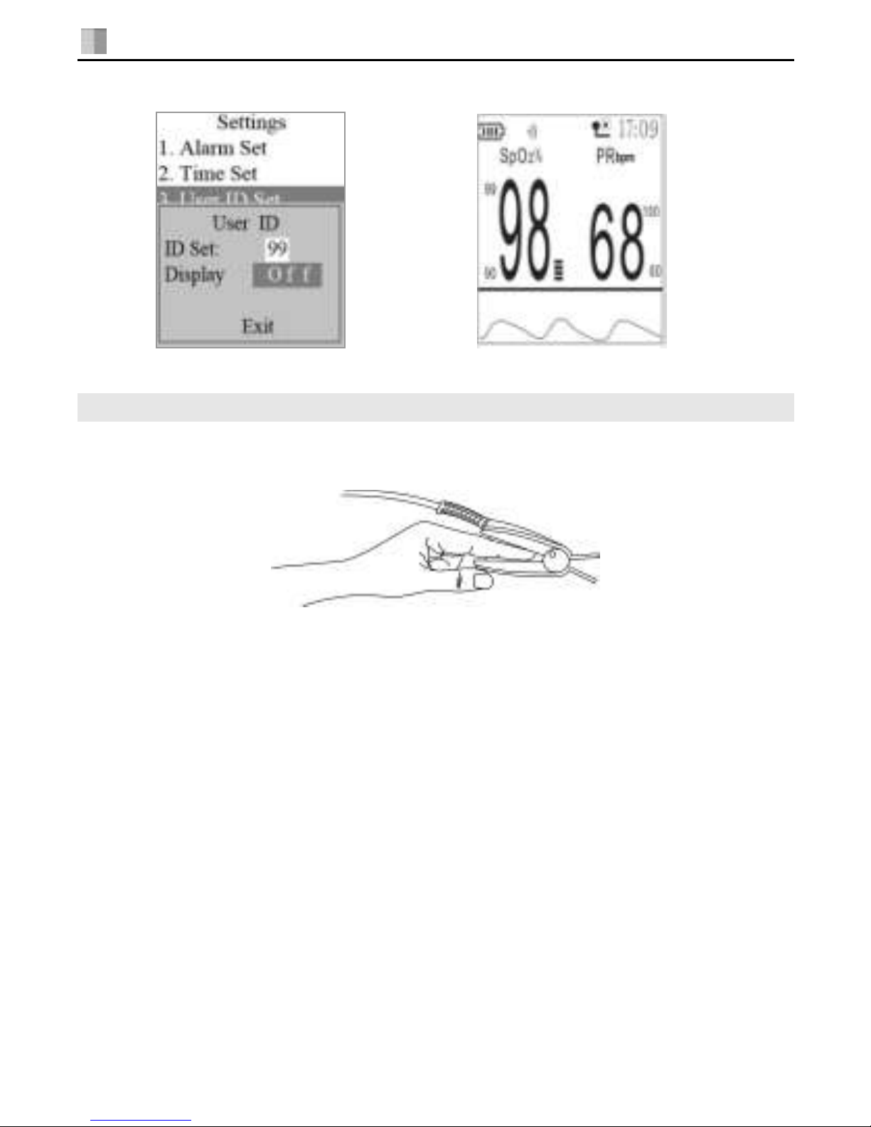
Tissue damage can be caused by incorrect application or use of sensor, for
example by wrapping the sensor too tightly. Inspect the sensor site to
ensure skin integrity and correct positioning and adhesion of the sensor.
More frequently inspection should be taken depend on different patients if
necessary.
Set the upper limit of SpO2alarm to 100% means cut off the upper alarm.
High density of oxygen will cause adverse affection to the neonate .So the
upper limit of SpO2alarm must be selected prudently according to the
acknowledged clinical practice.
Inaccurate measurements may be caused by:
Incorrect sensor application or use
Significant levels of dysfunctional hemoglobins (such as c
arboxyhemoglobin or methemoglobin)
Intravascular dyes such as indocyanine green or methylene blue
Exposure to excessive illumination, such as surgical lamps (especially
ones with a xenon light source), bilirubin lamps, fluorescent lights,
infrared heating lamps, or direct sunlight
High-frequency electro surgical interference and defibrillators
Venous pulsations
Placement of a sensor on an extremity with a blood pressure cuff,
arterial catheter, or intravascular line
The patient has hypotension, severe vasoconstriction, severe anemia,
or hypothermia
There is arterial occlusion proximal to the sensor
The patient is in cardiac arrest or is in shock
Loss of pulse signal can occur in any of the following situations:
The sensor is too tight
There is excessive illumination from light sources such as a
surgical lamp, a bilirubin lamp, or sunlight
A blood pressure cuff is inflated on the same extremity as the one to
which an SpO2sensor is attached
Note:Pulse sensor should obviate the light source, e.g. radial lamp or
infrared lamp.

V1.0I2 PULSE OXIMETER OPERATOR'SMANUAL
17
CHAPTER 6 Other Settings
6.1 Alarm Setting
Press the ENTER button to enter into the main menu and the “1. Alarm Set”
item is selected automatically, and then press the ENTER button to enter into
the Alarm Set submenu.
1) SpO2alarm setup
After you enter into the “Alarm Set”, the highlimit value below SpO2item is
selected automatically (refer to Fig.17), and then press the ENTER button to
highlight the value (refer to Fig.18). Press the UP button or the DOWN button
to adjust the value, and then press the ENTER button to finish the setup of
SpO2% upper alarm limit. The range of upper limit is 70-99.
Fig.17 Fig.18
In the Alarm Set submenu, press the UP button or the DOWN button to select
the lowlimit value below SpO2item(refer to Fig.19), and then press the ENTER
button to highlight the value(refer to Fig.20). Press the UP button or the
DOWN button to adjust the value, and then press the ENTER button to finish
the setup of SpO2% lower alarm limit. The range of lower limit is 69-98.
Fig.19 Fig.20

V1.0I2 PULSE OXIMETER OPERATOR'SMANUAL
18
2) PR alarm setup
In the Alarm Set submenu,you can press the UP button or the DOWN button
to select the highlimit value below PR item (refer to Fig.21), and then press the
ENTER button to highlight the value (refer to Fig.22). Press the UP button or
the DOWN button to adjust the value, and then press the ENTER button to
finish the setup of PR upper alarm limit. The range of upper limit is 31-235.
Fig.21 Fig.22
In the Alarm Set submenu, you can press the UP button or the DOWN
button to select the lowlimit value below PR item (refer to Fig.23), and then
press the ENTER button to highlight the value (refer to Fig.24). Press the UP
button or the DOWN button to adjust the value, and then press the ENTER
button to finish the setup of PR lower alarm limit. The range of lower limit is
30-234.
Fig.23 Fig.24

V1.0I2 PULSE OXIMETER OPERATOR'SMANUAL
19
3) Default-set
In the Alarm Set submenu,you can press the UP button or the DOWN button
to select the Default-set item(refer to Fig.25), and then press the ENTER
button to confirm the selection, synchronously returning to the main menu.
The default limits are displayed on the measuring screen (refer to fig.26).
Fig.25 Fig.26
3) Display setup
In the Alarm Set submenu, you can press the UP button or the DOWN button
to select the Display item, and then press the ENTER button to highlight the
value(refer to Fig.27). Press the UP button or the DOWN button to select
On/Off, and then press the ENTER button to confirm the setup. If you set
Display ”on”, SpO2% upper & lower alarm limit value and PR upper & lower
alarm limit value will be indicated in screen(refer to Fig.2). If you set it “off”, all
the alarm limit indicator will not be shown (refer to Fig.28).
Fig.27 Fig.28
In the Alarm Set submenu,you can press the UP button or the DOWN button
to select the “Exit”item, and then press the ENTER button to return to the
main menu.
Table of contents
Other Choice Medical Equipment manuals