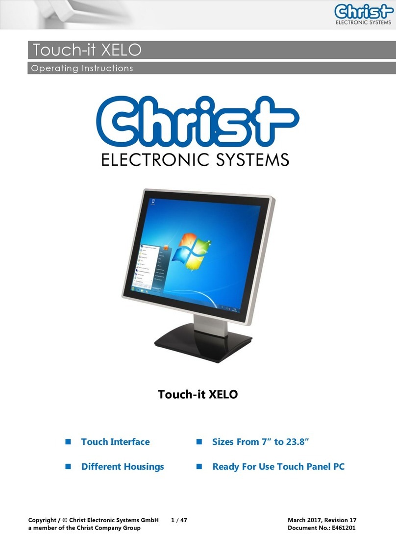
Christ VESA 12.1 OEM Product information sheet

Instruction Manual: Touch Industrial PC VESA 12.1 OEM
Doc. No.: PA10013282
2 / 32
Nov. 2023, Revision 02
1Identification 4
2Product description 6
2.1 System Overview 6
2.2 Housing 6
3Description Hardware 8
3.1 External Interfaces 8
4Mounting 13
4.1 Torque 13
4.2 Mounting 14
4.2.1 Dismounting the cover plate 15
4.2.2 Mounting the cover plate 15
4.2.3 Replacing the cable grommets 16
5Commissioning 17
5.1 Function of the power button 17
5.2 Unusual situations 17
5.2.1 Sluggish touch behavior 17
6Software 18
6.1 BIOS Basic Settings 18
6.1.1 BIOS Default Settings 18
6.1.2 Set Boot Priority 20
6.2 BIOS Update 21
6.2.1 Preparation 21
6.2.2 Perform Update 21
6.3 Redo Backup and Recovery 21
7Maintenance 22
7.1 Cleaning 22
7.2 Maintenance 22
7.2.1 Replacing the battery 22
8Technical Data 25
8.1 Mechanical Specifications 25
8.2 Electrical Specifications 25
8.3 Power Consumption 25
8.4 Environmental Conditions 26

Instruction Manual: Touch Industrial PC VESA 12.1 OEM
Doc. No.: PA10013282
3 / 32
Nov. 2023, Revision 02
8.5 Temperature test 26
9Standards and Approvals 27
9.1 CE Marking 27
9.2 UKCA Marking 27
9.3 RoHS 27
9.4 Electromagnetic Compatibility 27
9.5 FCC Approval 28
9.6 Environmentally Appropriate Disposal 28
10 Technical Support 30
10.1 Device Seal 30

Instruction Manual: Touch Industrial PC VESA 12.1 OEM
Doc. No.: PA10013282
4 / 32
Nov. 2023, Revision 02
1Identification
Target group
This document is not intended for end customers! Necessary safety instructions for the end cus-
tomer must be passed on by the machine builder or system provider and adopted in the re-
spective national language.
Intended use
The devices described in this documentation are intended to enable the user to control, oper-
ate, observe, drive and visualise certain processes in industry or industrial contexts / environ-
ments. The devices must be used within the conditions and limits described in this documenta-
tion.
Improper use
The devices have not been designed and manufactured for use in applications where serious
danger to life and health may occur. The equipment must not be used for the following pur-
poses:
•Control of nuclear reactions in nuclear power plants
•Control systems of weapons
•Automatic control of aircraft air traffic control and mass transport systems
•Medical equipment for life support
Technical changes
Christ Electronic Systems GmbH reserves the right to change the information, designs and
technical data contained in this documentation without prior notice.
History
The following editions of the manual have already been published:
Version
Comment
07/2023
Rev. 00
First edition
09/2023
Rev. 01
Chapter 4.2.3 Replacing the cable grommets: Link to icotek hopepage
inserted
Chapter 7.2.1 Replacing the battery: inserted
10/2023
Rev. 02
Chapter 1 Identification: intended use adapted; improper use inserted
Chapter 9.5 FCC Approval: inserted
Chapter 9.6 Environmentally Appropriate Disposal: Directive
2006/66/EC replaced by Regulation 2023/1542
Table 1: History

Instruction Manual: Touch Industrial PC VESA 12.1 OEM
Doc. No.: PA10013282
5 / 32
Nov. 2023, Revision 02
Design of safety instructions
The general structure of the safety instructions is shown below:
NOTICE
Type of hazard and source of hazard
Consequences in the event of non-compliance with the guideline
➢Measures to avoid hazards
The meaning of the colours of the safety instructions is shown below:
DANGER
Indicates an imminent danger
Failure to follow the instructions may result in death or serious injury.
WARNING
Indicates a dangerous situation
Failure to follow the instructions may result in serious injury.
CAUTION
Indicates a possible dangerous situation
Failure to follow the instruction may result in injury.
NOTICE
Indicates user tips and useful information
Important information to avoid malfunctions.

Instruction Manual: Touch Industrial PC VESA 12.1 OEM
Doc. No.: PA10013282
6 / 32
Nov. 2023, Revision 02
2Product description
2.1 System Overview
CPU
Intel® Celeron™ 3965U 2.2 GHz
Graphic
Intel® HD Graphics 610
Memory
4 GB DDR4
Mass Storage
64 GB 3D TLC SSD
BIOS
AMI Optio 5 BIOS
Interfaces
1 x M8 3-pin male connector A coded, Power; M8 4-pin
male connector A coded, Power / CAN-IN
2 x USB Host 3.0 (Type A), X33, X34
2 x USB Host 2.0 (Type A), X31, X32
2 x USB Host 2.0 (Type A) (side) (max. total current: 0.5 A)
2 x 1 Gbit Ethernet (1x RJ45 Intel® I211-AT, ETH X21; 1x
RJ45 Intel® I210-AT, ETH X22)
1 x RS-232 / RS-485 / RS-422 (Sub-D) (BIOS setting), Se-
rial X41
1 x CAN-IN (M8 4-pin male connector A coded), Power /
CAN-IN
1 x CAN-OUT (M8 4-pin female connector A coded),
Power / CAN-OUT
1 x Display Port 1.1, DP X71
Table 2: System overview
2.2 Housing
Illustration 1: Front
Illustration 2: Rear

Instruction Manual: Touch Industrial PC VESA 12.1 OEM
Doc. No.: PA10013282
7 / 32
Nov. 2023, Revision 02
Illustration 3: Dimensions
Illustration 4: Dimensions Rear
Dimensions are given in millimeters.
Size
A
B
C
D
12.1"
312
214
70
66
Table 3: Dimensions

Instruction Manual: Touch Industrial PC VESA 12.1 OEM
Doc. No.: PA10013282
8 / 32
Nov. 2023, Revision 02
3Description Hardware
The description of the hardware refers to the device interfaces and the possible extensions for
the device.
3.1 External Interfaces
NOTICE
External cable for Power Supply
Malfunction occur
➢Prepare a proper earth connection on the power supply
NOTICE
Signal and data cables
Malfunction occur
➢Signal and data cables must be shielded and of high quality.
NOTICE
Operating the interfaces outside their intended specification
Malfunctions occur and the electronics of the device can be damaged or
completely broken
➢All interfaces must be operated within their specification. Only cables
and components that meet the requirements for the intended use of
the interfaces may be connected.
USB Host 2.0 (Type A)
PIN
Function
Description
1
VBUS
USB VCC
2
D-
USB Data-
3
D+
USB Data+
4
GND
USB Ground
Table 4: Pinout USB 2.0

Instruction Manual: Touch Industrial PC VESA 12.1 OEM
Doc. No.: PA10013282
9 / 32
Nov. 2023, Revision 02
USB Host 3.0 (Type A)
PIN
Function
Description
1
VBUS
USB VCC
2
D-
USB Data-
3
D+
USB Data+
4
GND
USB Ground
5
StdA_SSRX-
SuperSpeed transmitter differential pair
6
StdA_SSRX+
SuperSpeed transmitter differential pair
7
GND_DRAIN
Ground for signal return
8
StdA_SSTX-
SuperSpeed receiver differential pair
9
StdA_SSTX+
SuperSpeed receiver differential pair
Table 5: Pinout USB 3.0
Ethernet Gigabit
PIN
Function
Description
1
D1+
Transmit Data +
2
D1-
Transmit Data -
3
D2+
Receive Data+
4
D3+
Bidirectional +
5
D3-
Bidirectional -
6
D2-
Receive Data -
7
D4+
Bidirectional +
8
D4-
Bidirectional -
Table 6: Pinout Ethernet Gigabit

Instruction Manual: Touch Industrial PC VESA 12.1 OEM
Doc. No.: PA10013282
10 / 32
Nov. 2023, Revision 02
Serial Connector (Titanium)
RS-232
RS-422
RS-485
PIN
Func-
tion
Description
Func-
tion
Description
Func-
tion
Description
1
DCD
Data Car-
rier Detect
TX-
Transmitter
Differential
Pair -
DATA-
Data Dif-
ferential
Pair A
2
RX
Receive
Data
TX+
Transmitter
Differential
Pair +
DATA+
Data Dif-
ferential
Pair B
3
TX
Transmit
Data
RX+
Receiver
Differential
Pair +
--
--
4
DTR
Data Trans-
mit Ready
RX-
Receiver
Differential
Pair -
--
--
5
GND
Ground
GND
Ground
GND
Ground
6
DSR
Data Set
Ready
--
--
--
--
7
RTS
Ready To
Send
--
--
--
--
8
CTS
Clear To
Send
--
--
--
--
9
RI
Ring Indi-
cator
--
--
--
--
Table 7: Pinout Serial Connector Titanium

Instruction Manual: Touch Industrial PC VESA 12.1 OEM
Doc. No.: PA10013282
11 / 32
Nov. 2023, Revision 02
Display Port
PIN
Function
Description
1
DP data 0+
DP data 0+
2
GND
Ground
3
DP data0-
DP data0-
4
DP data1+
DP data1+
5
GND
Ground
6
DP data1-
DP data1-
7
DP data2+
DP data2+
8
GND
Ground
9
DP data2-
DP data2-
10
DP data3+
DP data3+
11
GND
Ground
12
DP data3-
DP data3-
13
CONFIG1 CAD
Cable adapter recognized
14
CONFIG2
Ground (Pull-Down)
15
AUX_CH+
Additional device +
16
GND
Ground
17
AUX_CH-
Additional device -
18
HPD
Hot Plug recognized
19
GND
Ground
20
DP_PWR 3,3V
Power Supply DP
Table 8: Pinout Display Port
Display Port 1.1 is also known as "Dual-Mode Display Port" and "Display
Port++". This allows compatibility with DVI and HDMI.
M8 3-pin male connector
PIN
Function
Description
1
24 V (max. 4
A)
24 V (maximum 4 ampere)
2
--
--
3
GND
Ground
Table 9: Pinout M8 3-pin male connector

Instruction Manual: Touch Industrial PC VESA 12.1 OEM
Doc. No.: PA10013282
12 / 32
Nov. 2023, Revision 02
M8 4-pin male connector
PIN
Function
Description
1
24 V (max. 4
A)
24 V (maximum 4 ampere)
2
CAN_H
CAN High
3
GND
Ground
4
CAN_L
CAN Low
Table 10: Pinout M8 4-pin male connector
M8 4-pin female connector
PIN
Function
Description
1
24 V (max.
2.5 A)
24 V (maximum 2.5 ampere)
2
CAN_H
CAN High
3
GND
Ground
4
CAN_L
CAN Low
Table 11: Pinout M8 4-pin female connector

Instruction Manual: Touch Industrial PC VESA 12.1 OEM
Doc. No.: PA10013282
13 / 32
Nov. 2023, Revision 02
4Mounting
This chapter describes all the steps for assembly. The following warnings are safety instructions
that must be applied throughout the assembly chapter and in every other life cycle of the de-
vice.
NOTICE
Power Supply
Disturbance of the proper operation
➢The device must be operated with protective low voltage (< 28.8
VDC).
WARNING
Dropping a device
Injuries and bruises to the legs and / or feet
➢Wear safety shoes
Note for the installation site
This device is not designed for outdoor use.
Make sure that the ambient temperature and humidity are within the ranges which are speci-
fied under Environmental Conditions.
Do not install the device directly in the sunlight.
Make sure that the device is installed so that is accessible for the operator.
Installation instructions
Check the package contents for any visible damage and for completeness.
In case of damage, do not install the device and contact the Christ Service.
4.1 Torque
All screws must be tightened with the following torques.
Screw
Torque
M3
1.0 Nm
M4
2.3 Nm

Instruction Manual: Touch Industrial PC VESA 12.1 OEM
Doc. No.: PA10013282
14 / 32
Nov. 2023, Revision 02
4.2 Mounting
Step 1:
Completely unscrew all four nuts on the back of the device.
Illustration 5: Mounting
Step 2:
Push the threaded bolts through an assembly jig.
Step 3:
Screw all four nuts back onto the threaded bolts. The tightening torque is determined by the
customer.

Instruction Manual: Touch Industrial PC VESA 12.1 OEM
Doc. No.: PA10013282
15 / 32
Nov. 2023, Revision 02
4.2.1 Dismounting the cover plate
The cover plate can only be dismounted if it is not blocked.
Step 1:
Loosen all six screws marked in blue on the back of the device and store them together with
the serrated lock washer.
Step 2:
Remove cover plate.
Illustration 6: Dismounting the cover plate
4.2.2 Mounting the cover plate
Step 1:
Attach cover plate.
Step 2:
Screw on all six screws marked in blue together with the serrated lock washers.
Illustration 7: Mounting the cover plate

Instruction Manual: Touch Industrial PC VESA 12.1 OEM
Doc. No.: PA10013282
16 / 32
Nov. 2023, Revision 02
4.2.3 Replacing the cable grommets
Suitable cable grommets can be found on the icotek homepage: https://www.ico-
tek.com/en/products/cable-grommets/qt
If additional cables are routed out of the enclosure from the concealed interfaces, the cable
grommets must be removed and replaced with suitable cable grommets for the corresponding
cable diameters. The enclosure is designed for cable grommets from the manufacturer icotek.
To replace the cable grommets, they can be removed from the recess and pushed in.
Illustration 8: Replacing the cable grommets
The flat surface of the cable grommets must face the front of the device!
Illustration 9: Alignment of the cable grommets

Instruction Manual: Touch Industrial PC VESA 12.1 OEM
Doc. No.: PA10013282
17 / 32
Nov. 2023, Revision 02
5Commissioning
To put the device into operation, connect the power supply to the unit.
The device starts.
Further steps for commissioning are not necessary.
5.1 Function of the power button
If the device has a power button, it behaves according to the following standard.
When the device is plugged into the power supply, the device boots up without having to press
the power button.
If the power button is pressed while the device is running, the device shuts down.
If the power button is pressed while the device is not running, the device starts up. The power
supply must be present at the device.
Notice:
A different behaviour may occur if the device does not have the standard configuration.
5.2 Unusual situations
Under certain circumstances, the unit may behave in an unusual way. These are listed below.
5.2.1 Sluggish touch behavior
Description of error:
The touch´s functionality is affected. The touch only triggers irregularly and behaves slug-
gishly.
Description:
This behavior can be caused by the power supply unit if there is no conductive connection be-
tween the PE of the primary side and the GND of the secondary side.
Solution:
A power supply unit must be used with a conductive connection between the PE of the primary
side and the GND of the secondary side.

Instruction Manual: Touch Industrial PC VESA 12.1 OEM
Doc. No.: PA10013282
18 / 32
Nov. 2023, Revision 02
6Software
The Software chapter describes settings and functions that may be required to use the device.
6.1 BIOS Basic Settings
AMI BIOS ROM has built-in settings program that allows users to make basic settings. This in-
formation is stored in a battery supported CMOS RAM, so it remains stored even when there is
no power supply.
Accessing the BIOS works by pressing the "Del" key several times while the device is booting.
The following tabs in the BIOS enable various settings.
Main
Set date
Advanced
Make advanced BIOS settings like: COM, ACPI, etc.
Chipset
SATA and RST configuration
Security
Set administrator password
Boot
Set Boot Option
Save & Exit
Save the settings made and initiate a restart. (Also possible
with the F4 key on the keyboard)
Table 12: BIOS
Pressing F3 and confirming the query "Load Optimized Defaults?" with "Yes" restores the deliv-
ery state.
Illustration 10: BIOS
6.1.1 BIOS Default Settings
The BIOS is password protected. Please note that the keyboard layout for entering the BIOS
password is English. The BIOS password is case sensitive and must be entered in the same
way.

Instruction Manual: Touch Industrial PC VESA 12.1 OEM
Doc. No.: PA10013282
19 / 32
Nov. 2023, Revision 02
The following default settings are already made in the BIOS.
LVDS Configuration
Illustration 11: BIOS LVDS Configuration
Setting Attempt Secure Boot
Secure Boot is activated in this BIOS. This means that only signed images can be started.
Illustration 12: BIOS Attempt Secure Boot

Instruction Manual: Touch Industrial PC VESA 12.1 OEM
Doc. No.: PA10013282
20 / 32
Nov. 2023, Revision 02
Installed Keys for the Secure Boot
Illustration 13: BIOS Keys for the Secure Boot
Settings in the Boot tab
Illustration 14: BIOS Boot
6.1.2 Set Boot Priority
If you want to boot from a USB device, the following settings must be made in the BIOS:
1. Select "Boot" tab
2. Select "Boot mode select" "UEFI"
3. Open the "Boot Option #1" by pressing the "Enter" key
4. Select USB device with "Enter"
5. Save with keystroke "F4" (confirmation with "Yes")
Table of contents
Other Christ Industrial PC manuals
Popular Industrial PC manuals by other brands

DMP Electronics
DMP Electronics EBOX EB-AN Series user guide

Omron
Omron DYALOX INDUSTRIAL PC quick start guide

Wilke Technology
Wilke Technology ICOM 200 manual

ADLINK Technology
ADLINK Technology DLAP-4000 Series user manual

IFM
IFM moneo appliance QHA300 Instructions for setup

Xycom
Xycom 3700 Series user manual