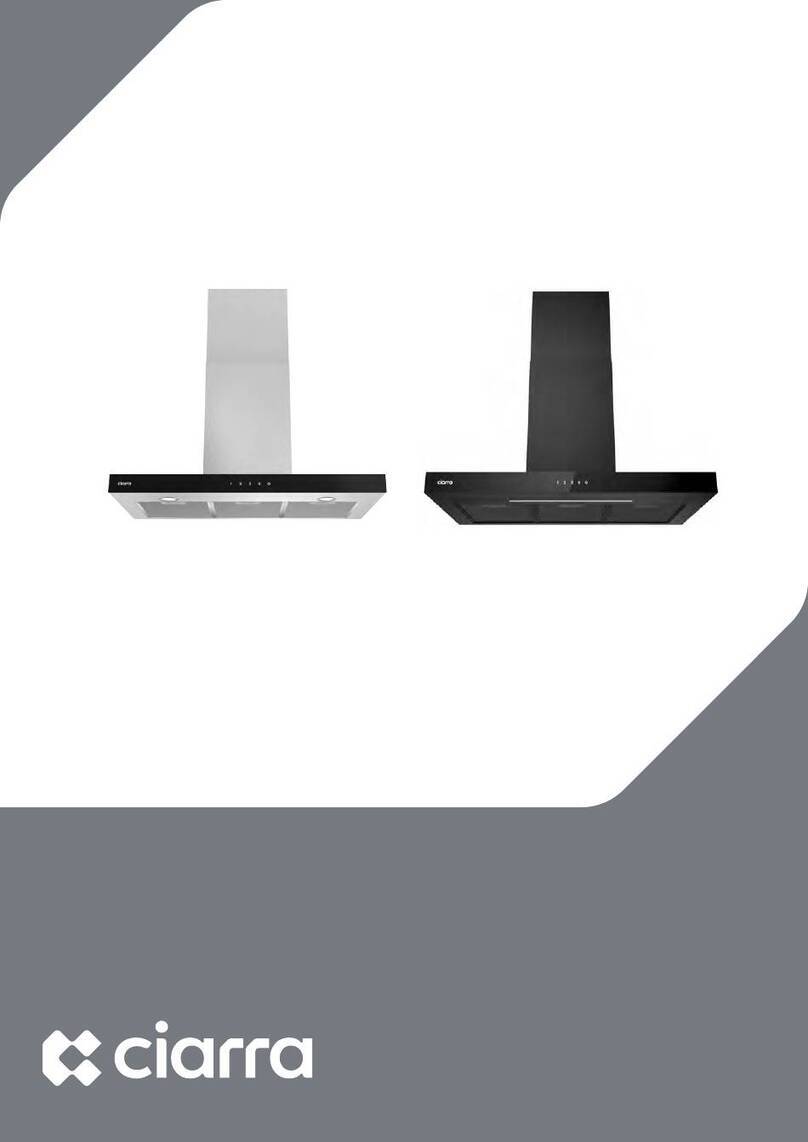
CIARRA CBCS9301 User manual

Model Number:
CBCS9301
www.ciarraappliances.com


EN
Dear customer:
Thank you so much for your purchase, please read this instruction
manual carefully before installation & use.
If you have any question, please contact us at:
E-mail: info@ciarraappliances.com
ENGLISH INSTALLATION AND USER'S MANUAL Page
3-23
DEUTSCH BENUTZERHANDBUCH&INSTALLATION
SANLEITUNG
Seite
24-46
FRANÇAIS
MANUEL DE L’UTILISATEUR ET
D’INSTALLATION
Page
47-69
1

EN
CONTENTS
Safety------------------------------------------- 3-4
Specifications--------------------------------------5
Before Using the Cooker Hood ---------------------6
Prepare for Installation ----------------------------7
Installation--------------------------------------8-17
Install the Hood-------------------------------------------8-16
Carbon Filter Installation------------------------------------17
Operation----------------------------------------- 18
Cleaning and Maintenance---------------------19-21
Grease Filter------------------------------------------------19
Carbon Filter -----------------------------------------------19
Stainless Steel Cleaning ------------------------------------19
Painted Finish Cleaning-------------------------------------19
LED Replacement---------------------------------------20-21
Troubleshooting-----------------------------------22
Environmental Protection -------------------------23
2

EN
Safety
!WARNING
TO REDUCE THE RISK OF FIRE, ELECTRIC SHOCK, OR
INJURY TO PERSONS, OBSERVE THE FOLLOWING:
Use this unit only in the manner intended by the
manufacturer. Ifyou have questions, contact the
manufacturer at the address or telephone number listed in
the warranty.
Before servicing or cleaning unit, unplug ordisconnect the
cooker hood from the power supply.
This appliance isnot intended for useby persons (including
children) with reduced physical, sensory ormental
capabilities, or lack of experience andknowledge, unless
they havebeen given supervision orinstruction concerning
use of the appliance bya person responsible for their safety.
Installation work and electrical wiring must be done by a
qualified person(s) in accordance with all applicable codes
and standards, including fire-rated construction.
Sufficient air is needed for proper combustion and
exhausting of gases through the flue (chimney) of fuel
burning equipment to prevent back drafting.
When cutting or drilling into a wall or ceiling, do not damage
electrical wiring and other hidden utilities.
Ducted fans must always be vented to the outdoors.
Ensure the requirements of the local authorities are adhered
to concerning the discharge of exhaust air.
This unit must be grounded.
When applicable local regulations comprise more restrictive
installation and/or certification requirements, the
aforementioned requirements prevail on those of this
document and the installer agrees to conform to these at his
own expense.
Clean cooker hood frequently. Grease should not be allowed
to accumulate on fans, filters or in exhaust ducts.
Warning: Failure to install the screws or fixing device in
accordance with these instructions may result in electrical
hazards.
3

EN
Safety
!
WARNING
TO REDUCE THE RISK OF INJURY TO PERSONS IN THE EVENT
OF A RANGE TOP GREASE FIRE, OBSERVE THE FOLLOWING*:
1. SMOTHER FLAMES with a close-fitting lid, cookie sheet or
metal tray, then turn off the burner. BE CAREFUL TO
PREVENT BURNS. IF THE FLAMES DO NOT GO OUT
IMMEDIATELY, EVACUATE AND CALL THE FIRE
DEPARTMENT.
2. NEVER PICK UP A FLAMING PAN — You may be burned.
3. DO NOT USE WATER, including wet dishcloths or towels —
This could cause a violent steam explosion.
4. Use an extinguisher ONLY if:
a) You own a Class ABC extinguisher and you know how to
operate it.
b) The fire is small and contained in the area where it
started.
c) The fire department has been called.
d) You can fight the fire with your back to an exit.
!CAUTION
For indoor useonly.
For general ventilating use only. Do not use to exhaust hazardous or
explosive materials andvapors.
To avoid motor bearing damage andnoisy and/or unbalanced fan
blade, keep drywall spray, construction dust, etc. offcooker hood.
Yourhood motor has a thermal overload which will automatically
shut offthe motor ifitbecomes overheated. The motor will restart
when itcools down. Ifthe motor continues to shut offandrestart,
have the hood serviced.
Always follows the cooking equipment manufacturer’s requirements
regarding the ventilation needs.
To reduce the risk of fire andto properly exhaust air, besure toduct
air outside — Do not exhaust airinto spaces within walls or ceiling or
into attics, crawl space orgarage.
When installing, servicing or cleaning the unit, itisrecommended to
wear safety glasses andgloves.
Please read specification label on product for further information
and requirements.
4

EN
Specifications
5
Voltage 220V-240V~ 50Hz
Power of Motor 1 x 100W
Power of lamps 2x 2W
Appliance Dimension 900*500*640~1020mm
(W x D x H)
Note: The manufacturer reserves the right to change any
technological improvement or modification without prior notice.
CBCS9301
CBCB9301

EN
Before Using the Cooker Hood
CAUTION: Before proceeding to the installation, check If items
are missing or damaged, contact the manufacturer.
Observe all governing codes and ordinances. Have a qualified
technician install the cooker hood. It is the installer’s
responsibility to comply with installation clearances specified on
the model/serial rating plate. The manufacturer declines all
responsibility for improper installation and does not accept
responsibility for appliance warranty in the event of damage
caused by incorrect installation.
6
COMPONENTS:
YOU WILL BE NEEDING THESE TOOLS FOR INSTALLATION
1.Protective Gloves
2.Spirit Level Ruler
3.Measuring Tape
4.Double Sided Tape or Tape
5.Cross-Head Screwdriver Set
6.Electric drill and 8mm drill
Part 1 : Wall Plug X 9
Part 2 : 4*30mm Screws X 9
Part 3 : 4*8mm Screws X 6
Part 4 : Aluminum Exhaust Pipe X 1
Part 5 : Cable Ties X 2
Part 6 : Installation Manual X 1
Part 7 : 1:1 Installation Diagram X 1
Part 11 : Cooker Hood Body X 1
Part 12 : Lower Chimney X 1
Part 13 : Upper Chimney X 1
Part 9 : Upper Chimney Bracket X 1
Part 10 : Wall Bracket X 1
Part 8 : Lower Chimney Bracket X 1

EN
Prepare for Installation
7
Prepare for Installation:
a) Ventilation Mode
Recirculation Mode: Recirculating with carbon filter (required), the
smells and odors can be filtered and vented through the top
vented hole and the exhaust pipe is not required.
Extraction Mode: You can install the 1.5m long and 150mm
diameter aluminum exhaust pipe for extracting, which is included in
the installation kit.
b) When possible, use at least 60cm straight runs before any turns. Larger
duct work may be required for best performance with longer duct runs.
c) Before installation, don't connect the power.

EN
Installation
Install the Hood(Extraction):
1) Remove all protective poly film from the hood and/or parts.
2) Recommend installation height: 65~75cm above the cooktop for
best extraction.
Required height over gas hob: 750mm;
Required height over electric hob: 650mm.
8
650mm
750mm

EN
Installation
3) First use a pencil to mark the installation position on the wall, then
use a Measuring Tape to measure the height from the stove surface
to the hood (the center point of aluminum grease filter) and use a
Spirit Level Ruler to maintain the level, then use a pencil to draw a
horizontal line along the level.
4) Poke the 7 perforated positions on the 1:1 Installation Diagram, then
align the with button line of the hood on the Installation Diagram
with the horizontal line on the wall, then tape the Installation
Diagram to the wall, and use a pencil to mark the perforated
positions on the wall in the corresponding positions.
9
Spirit Level Ruler
650mm 750mm
1:1 Installation Diagram
Tape
COMPONENTS:
Part 7: 1 :1 Installation Diagram X 1

EN
Installation
5) Determine the maximum chimney installation height according to
the actual scenario and mark the chimney installation locations
along the center line of the Installation Diagram.
6) Remove the Installation Diagram, drill the holes that have been
marked on the wall with an Electric Drill (8mm drill), and hammer
the Wall Plug into the wall.
10
Chimney
installation
locations
Wall Plug
COMPONENTS:
Part 1: Wall Plug X 9

EN
Installation
7) Use three 4*30mm Screws to fasten the Wall Bracket on the wall.
11
8) Remove the aluminum grease filter and hang the hood on the
corresponding hook of the Wall Bracket.
4*30mm Screws
4*30mm Screws
COMPONENTS:
Part 2: 4 *30mm Screws X 3
Part 10: Wall Bracket X 1

EN
Installation
9) Use a Spirit Level Ruler to measure whether the hood is in a
horizontal level, and use two 4*30mm Screws to lock into the safety
hole position of the hood (not mandatory, according to user's wishes
to choose whether to lock).
NOTE:
Make sure you remove the tape on the damper and check if the
damper opens and closes freely, otherwise it make noises, and the
cooker hood will be shaking.
12
10) Tear off the tape from the air outlet.
Spirit Level Ruler
4*30mm Screws
Tape
COMPONENTS:
Part 2: 4*30mm Screws X 2

EN
Installation
11) Install the Aluminum Exhaust Pipe into the air outlet and lock it with
a Cable Tie; the other end of the Aluminum Exhaust Pipe will be
pulled upward to outdoor and lock it with a Cable Tie (Note: This
step can be ignored if use as recirculation mode with carbon filter).
13
12) Use two 4*8mm Screws to fasten the Lower Chimney Bracket on the
Lower Chimney.
Aluminum
Exhaust Pipe
Lower Chimney
Upper Chimney
Lower
Chimney
Bracket
Upper
Chimney
Bracket
Lower Chimney
Bracket
Lower Chimney
4*8mm
Screws
Cable Tie
COMPONENTS:
Part 4: Aluminum Exhaust Pipe X 1
Part 5: Cable Tie X 1
COMPONENTS:
Part 8: Lower Chimney Bracket X 1
Part 12: Lower Chimney X 1
Part 3: 4*8mm Screws X 2

EN
Installation
13) Insert the Lower Chimney into the hood and fix it to the
corresponding positioning hole with two 4*8mm Screws. (Note: That
the power cord needs to go through the chimney and connect the
power).
14
14) Use two 4*30mm Screws to lock the Lower Chimney Bracket into the
corresponding positioning holes on the wall.
Power Plug
4*8mm Screws
4*30mm
Screws
COMPONENTS:
Part 3: 4*8mm Screws X 2
COMPONENTS:
Part 2: 4*30mm Screws X 2

EN
Installation
15) Use two 4*30mm Screws to lock the Upper Chimney Bracket to the
corresponding positioning holes on the wall.
15
Upper Chimney
4*30mm
Screws
16) Put the Upper Chimney into the Lower Chimney, and then pulled
to the height of the Upper Chimney Bracket.
COMPONENTS:
Part 9: Upper Chimney Bracket X 1
Part 2: 4*30mm Screws X 2
COMPONENTS:
Part 13: Upper Chimney X 1

EN
Installation
17) Use two 4*8mm Screws to assemble the Upper Chimney on the
Upper Chimney Bracket.
16
4*8mm Screws
Upper
Chimney
Bracket
18) Turn the LED lights on/off, and test whether the functions are working
properly.
COMPONENTS:
Part 3: 4*8mm Screws X 2

EN
Installation
Carbon Filter Installation(Recirculation):
1. Carbon filter can be used to trap odors.
In order to install the carbon filter, the grease filter should be
detached first. Press the lock and pull it down.
3. If the carbon filter needs to be replaced, please turn it in the anti-
clockwise direction.
NOTE:
Make sure the carbon filter is securely locked.
When the carbon filter is installed, the suction of the cooker hood
will be reduced.
The carbon filter should be changed every 3 months depending on
the conditions of use.
17
2. Place the carbon filter into the unit and turn it in the clockwise
direction to lock it in place.

EN
Operation
Always turn your hood on before you begin cooking to establish an
airflow in the kitchen.
Let the blower run for a few minutes to clear the air after you turn off
the hood. This will help to keep the entire kitchen clean and fresh.
Mechanical Push button
Operate the hood as follows:
Off button
It's used to turn off the fan.
Low Speed button
For air ventilation with barely no noise; or simmering with very little
smoke and steam.
Medium Speed button
For your everyday cooking purpose.
High Speed button
High-Speed for stir-fry or cooking with lots of smoke and grease
produced.
Light button
When lights are OFF, press this button once to turn ON the lights. Press
this button again to turn OFF the lights.
18
Table of contents
Languages:
Other CIARRA Ventilation Hood manuals

CIARRA
CIARRA 736G User manual

CIARRA
CIARRA CBCS6906D User manual

CIARRA
CIARRA CBCS6201 User manual

CIARRA
CIARRA CBCB6903 User manual

CIARRA
CIARRA CAS52913E User manual

CIARRA
CIARRA CBCB6736F User manual

CIARRA
CIARRA CBCS5913 User manual

CIARRA
CIARRA CBCS5913A User manual

CIARRA
CIARRA CBCB6736M User manual

CIARRA
CIARRA 736F User manual

CIARRA
CIARRA CAS75918A User manual

CIARRA
CIARRA CBCS6506C-OW User manual

CIARRA
CIARRA CBCS6102 User manual

CIARRA
CIARRA CBCS6903 User manual

CIARRA
CIARRA CBCB6736C User manual

CIARRA
CIARRA CBCS6506B User manual

CIARRA
CIARRA Hood To Go User manual
CIARRA
CIARRA CBCS6125 User manual

CIARRA
CIARRA Hood To Go User manual

CIARRA
CIARRA CBCB4850 User manual