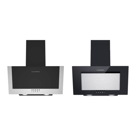
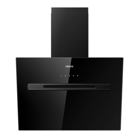
CIARRA 736G User manual

Ciarra 736G
User Manual • Uživatelský manuál •
Užívateľský manuál • Használati utasítás •
Benutzerhandbuch

2
English
3 –33
Čeština
34 –60
Slovenčina
61 –87
Magyar
88 –114
Deutsch
115 –141

3
Dear customer,
Thank you for purchasing our product. Please read the following instructions carefully
before first use and keep this user manual for future reference. Pay particular attention
to the safety instructions. If you have any questions or comments about the device,
please contact the customer line.
www.alza.co.uk/kontakt
✆+44 (0)203 514 4411
Importer Alza.cz a.s., Jankovcova 1522/53, Holešovice, 170 00 Praha 7, www.alza.cz

4
Safety Precautions
In order to minimize the potential for fire, electric shock, or harm to individuals,
please adhere to the subsequent guidelines:
•Operate this appliance solely as intended by the manufacturer. If you have inquiries,
reach out to the manufacturer using the address or phone number provided in the
warranty.
•Before conducting any maintenance or cleaning on the unit, make sure to unplug or
disconnect the cooker hood from its power source.
•This device is not designed for utilization by individuals (including children) with
diminished physical, sensory, or mental capacities, or those lacking experience and
knowledge—unless they are supervised or instructed on its use by a responsible
person ensuring their safety.
•Qualified personnel must carry out installation and electrical wiring activities,
following all relevant codes and standards, including those related to fire-resistant
construction.
•Adequate air supply is essential for proper combustion and the expulsion of gases
through the flue (chimney) of fuel-burning equipment to prevent reverse airflow.
•When working on walls or ceilings, exercise caution to avoid harming concealed
electrical wiring and utilities while cutting or drilling.
•Ducted fans must be consistently vented to the external environment.
•Comply with local authorities' regulations concerning the discharge of exhaust air.
•Ensure the proper grounding of this unit.
•If local regulations impose stricter installation or certification prerequisites, these
take precedence over the ones mentioned in this document. The installer commits to
adhering to these more stringent requirements at their own cost.
•Regularly clean the cooker hood. Prevent the build-up of grease on fans, filters, or
within exhaust ducts.
Warning: Neglecting to properly install the screws or fixing device as directed by these
instructions could lead to potential electrical dangers.

5
To minimize the possibility of harm to individuals in case of a grease fire on the
range top, please take note of the following precautions:
1. Extinguish flames by placing a well-fitting lid, cookie sheet, or metal tray over them,
then turning off the burner. Be cautious to avoid burns. If the flames persist,
evacuate and contact the fire department immediately.
2. Avoid picking up the burning pan —You may be burned.
3. Avoid using water, including damp dishcloths or towels —This could result in a
dangerous steam explosion.
4. Utilize an extinguisher only if:
a) You possess a Class ABC extinguisher and are familiar with its operation.
b) The fire is minor and contained to its point of origin.
c) The fire department has been notified.
d) You can combat the fire while having an exit route at your back.
Caution
•Intended solely for indoor usage.
•Designed exclusively for general ventilation purposes: Refrain from employing it to
expel hazardous or explosive substances and vapors.
•To prevent motor bearing impairment, as well as the development of a noisy or
imbalanced fan blade, ensure that drywall spray, construction dust, etc., are kept
away from the cooker hood.
•Your hood's motor incorporates a thermal overload feature that will automatically
deactivate the motor if it becomes excessively heated. The motor will resume
operation once it has cooled down. If the motor repeatedly shuts off and restarts,
seek professional servicing for the hood.
•Always adhere to the ventilation requirements outlined by the manufacturer of your
cooking equipment.
•To minimize the risk of fire and to effectively expel air, make sure to channel air
outdoors —Do not discharge air into enclosed spaces within walls or ceilings, attics,
crawl spaces, or garages.
•When installing, servicing, or cleaning the unit, it is advisable to wear safety glasses
and gloves.
•Kindly refer to the specification label on the product for additional information and
stipulations.

6
Specifications
Voltage
220V –240V ~ 50Hz
Power of Motor
1× 80W
Power of Lamps
1× 1W + 2,5W (UV)
Appliance Dimension (W × D × H)
595 × 420 × 810 ~1190mm
Note: The manufacturer reserves the right to change any technological improvement or
modification without prior notice.
Adjustable Chimney

7
Before Using the Cooker Hood
Caution: Prior to commencing the installation process, verify the presence and
condition of all items. In case of any missing or damaged components, get in touch with
the manufacturer. Adhere to all relevant codes and regulations. Employ a skilled
technician to carry out the installation of the cooker hood. The installer is accountable
for adhering to the installation clearances stipulated on the model/serial rating plate.
The manufacturer disclaims any liability for inappropriate installation and will not
assume responsibility for appliance warranties in instances where damage arises due to
incorrect installation.
Packaging
9× 4 × 30mm Screws
9× Wall Plug
1× Aluminum Exhaust Pipe
1× 1:1 Installation Diagram
1× Installation Manual
1× Cooker Hood Body
1× Lower Chimney
1× Upper Chimney
1× Carbon Filter (CBCF006)
6× 4 × 8mm Screws
2× Cable Ties
1× Wall Bracket
1× Upper Chimney Bracket
1× Lower Chimney Bracket

8
Tools Required for Installation
Preparations For Installation
Ventilation Mode
Recirculation Mode: By utilizing a carbon filter (mandatory), the recirculation process
effectively filters and expels odors and smells through the upper vented opening,
eliminating the need for an exhaust pipe.
Extraction Mode: You have the option to set up the included 1,5m long and 150mm
diameter aluminum exhaust pipe for extraction purposes.
1. Protective Gloves
2. Spirit Level Ruler
3. Measuring Tape
4. Double Sided or Normal Tape
5. Crosshead Screwdriver Set
6. Electric and 8mm drill

9
Optimizing Duct Layout for Improved Performance
Whenever feasible, incorporate straight runs of at least 60cm before introducing any
bends. Consider employing larger ductwork for optimal performance over extended
duct runs.
Don't Connect to Power Yet
Refrain from connecting the product to the mains power supply before installation.

10
Installation
Installation of the Hood (Extraction)
1. Take off all protective poly film from the hood and/or its components.
2. It is advised to install at a height of 65 - 75cm above the cooktop for optimal
extraction.
a. Minimum height over a gas hob: 750mm.
b. Minimum height over an electric hob: 650mm.

11
3. Begin by marking the installation position on the wall using a pencil. Next, employ a
Measuring Tape to gauge the height from the stove surface to the hood (center point
of the aluminum grease filter). Utilize a Spirit Level Ruler to ensure a level setup, and
finally, draw a horizontal line along this level using a pencil:
4. Puncture the 7 marked spots on the 1:1 Installation Diagram. Align the hood's button
line on the Installation Diagram with the wall's horizontal line, affixing the Installation
Diagram in place. Proceed to mark the corresponding perforated spots on the wall
using a pencil.
Spirit Level Ruler
Tape
Components:
1× 1:1 Installation Diagram
1:1 Installation Diagram

12
5. Based on the specific situation, establish the highest possible chimney installation
height and mark the chimney's installation spots along the center line of the
Installation Diagram.
6. Take down the Installation Diagram, use an Electric Drill (with an 8mm bit) to bore
holes in the previously marked positions on the wall, then insert the Wall Plugs by
tapping them into the holes.
Chimney Installation
Locations
Wall Plug
Components:
9× Wall Plug

13
7. Secure the Wall Bracket to the wall using three 4 × 30mm Screws.
Components:
3× 4 × 30mm Screws
1× Wall Bracket
4 × 30mm Screws
4 × 30mm Screws

14
8. Detach the aluminum grease filter, then suspend the hood onto the appropriate
hook of the Wall Bracket.

15
9. Utilize a Spirit Level Ruler to check if the hood is horizontally aligned, and if desired,
fasten it using two 4 × 30mm Screws into the designated safety holes (optional,
based on user preference).
Components:
2× 4 × 30mm Screws
4 × 30mm Screws
Spirit Level Ruler

16
10. Tear off the tape from the air outlet.
Note: Ensure to peel off the tape from the damper and verify that it can open and close
smoothly; otherwise, it might result in noise and potentially cause the cooker hood to
shake.
11. Insert the Aluminum Exhaust Pipe into the air outlet and secure it using a Cable Tie.
The opposite end of the Aluminum Exhaust Pipe should be extended upward and
fastened outdoors using another Cable Tie (Note: This step is not necessary when
using the recirculation mode with a carbon filter).
Tape
Aluminum
Exhaust Pipe
Cable Tie
Components:
1× Aluminum Exhaust Pipe
1× Cable Tie

17
12. Attach the Lower Chimney Bracket to the Lower Chimney using two 4 × 8mm Screws.
13. Slide the Lower Chimney into the hood and secure it to the appropriate positioning
hole using two 4 ×8mm Screws. (Note: Ensure the power cord is threaded through
the chimney for connection to the power source).
Upper Chimney
Upper Chimney
Bracket
Lower Chimney
Bracket
Lower Chimney
Lower Chimney
Lower Chimney
Bracket
4 × 8mm
Screws
Components:
1× Lower Chimney Bracket
1× Lower Chimney
2× 4 × 8mm Screws
4 × 8mm Screws
Power Plug
Components:
2× 4 × 8mm Screws

18
14. Fasten the Lower Chimney Bracket onto the wall's designated positioning holes using
two 4 × 30mm Screws.
15. Secure the Upper Chimney Bracket onto the wall's designated positioning holes
using two 4 × 30mm Screws.
Components:
2× 4 × 30mm Screws
4 × 30mm
Screws
4 × 30mm
Screws
Components:
1× Upper Chimney Bracket
2× 4 × 30mm Screws

19
16. Insert the Upper Chimney into the Lower Chimney, then extend it to match the
height of the Upper Chimney Bracket.
Components:
1× Upper Chimney
Upper Chimney

20
17. Attach the Upper Chimney to the Upper Chimney Bracket using two 4 × 8mm Screws.
18. Switch the LED lights on/off and verify the proper functionality of the functions.
Components:
2× 4 × 8mm Screws
4 × 8mm Screws
Table of contents
Languages:
Other CIARRA Ventilation Hood manuals

CIARRA
CIARRA CAS75918A User manual

CIARRA
CIARRA CBCS6906D User manual

CIARRA
CIARRA CBBIH3 User manual

CIARRA
CIARRA CBCS6506S User manual

CIARRA
CIARRA CBCS6506B User manual
CIARRA
CIARRA CBCS6201 User manual

CIARRA
CIARRA CBCB6736F User manual

CIARRA
CIARRA CBCB4850 User manual

CIARRA
CIARRA CBCS4820 User manual

CIARRA
CIARRA CBCS9102P User manual

CIARRA
CIARRA CBCS5913 User manual

CIARRA
CIARRA CBCB6736G User manual

CIARRA
CIARRA CBCS6803 User manual

CIARRA
CIARRA CBCS6903 User manual

CIARRA
CIARRA CBCS5913A User manual

CIARRA
CIARRA CAS75206W User manual

CIARRA
CIARRA CBCB6725 User manual

CIARRA
CIARRA CBCB6736M User manual

CIARRA
CIARRA CBCS9301 User manual

CIARRA
CIARRA CBCS6102 User manual