CIAT HCompact2 HA Series Guide

NA 12.65 D 05 - 2015
BROCHURE
Installation
Operation
Commissioning
Maintenance
HCompact2 HA

HEAT PUMPS -AIR CONDITIONING - REFRIGERATION - AIR HANDLING - HEAT EXCHANGE - NA 12.65 D
2
Horizontal package air conditionners
HCompact2 HA
Contents
1. Introduction..........................................................................................................................................................................................................3
2. Operation limits....................................................................................................................................................................................................3
3. Technical characteristics (EN-14511-2013).........................................................................................................................................................4
4. Unit identification.................................................................................................................................................................................................5
5. Safety advice.......................................................................................................................................................................................................5
6. Transport .............................................................................................................................................................................................................6
7. Location and assembling.....................................................................................................................................................................................6
Location designation.........................................................................................................................................................................................6
Assembling........................................................................................................................................................................................................6
Sound level .......................................................................................................................................................................................................7
Anchorage for silent-blocks...............................................................................................................................................................................7
Minimum free space for commissioning and maintenance operations .............................................................................................................7
8. Checking before commissioning..........................................................................................................................................................................8
Electrical Connections.......................................................................................................................................................................................8
Checks at centrifugal fans.................................................................................................................................................................................9
Interchangeable position of air supply...............................................................................................................................................................9
Interchangeable position of air return..............................................................................................................................................................10
Air ducts connections......................................................................................................................................................................................10
Condensate drain connection .........................................................................................................................................................................10
9. Safety elements.................................................................................................................................................................................................11
Low pressure pressostat.................................................................................................................................................................................11
High pressure pressostat................................................................................................................................................................................11
Magnetothermals for line protection................................................................................................................................................................11
Main door switch.............................................................................................................................................................................................11
Anti-fire safety.................................................................................................................................................................................................11
Safeties at the compressor .............................................................................................................................................................................11
Automatic switch in the control circuit.............................................................................................................................................................11
Air flow control (optional).................................................................................................................................................................................11
Clogged filter detector (optional).....................................................................................................................................................................11
10. Options............................................................................................................................................................................................................12
Condensation pressure control.......................................................................................................................................................................12
Electrical heater ..............................................................................................................................................................................................12
Filters ..............................................................................................................................................................................................................13
11. Commissioning................................................................................................................................................................................................14
Checks prior to commissioning.......................................................................................................................................................................14
Operational checks .........................................................................................................................................................................................14
Possible problems at commissioning..............................................................................................................................................................14
12. Maintenance....................................................................................................................................................................................................15
13. Control and analysis of breakdowns................................................................................................................................................................17

HEAT PUMPS -AIR CONDITIONING - REFRIGERATION - AIR HANDLING - HEAT EXCHANGE - NA 12.65 D 3
Horizontal package air conditionners
HCompact2 HA
1. INTRODUCTION
The HCompact2 HA heat pumps and cooling unit are packages air to
airunits,ofhorizontal compactconstruction, madefor operationindoors.
They are equipped with centrifugal fans, air coils, scroll compressor
and electronic control with microprocessor, optimized components for
the R-410A refrigerant.
Are appropriate for air conditioning applications in medium power in
offices, commercial and industrial spaces where the facade aesthetics
must be preserved.
•HCompact2 RHA Series: Air to air cooling autonomous units.
• HCompact2IHASeries:Reversibleairtoairheat pump autonomous
units.
Cooling capacity:
Heating capacity: 12,5 to 35,9 kW
14,2 to 41,0 kW
Theunits comply withstandards: EN60-204- EN378-2, and directives:
Machinery 2006/42 EC - EMC 2004/108/EC - LVD 2006/95 EC - PED
14/068 EC (Category 2).
After manufacturing, all units are charged with refrigerant and
are tested at the factory, verifying the correct operation of all their
componentswithin the operatingrange forwhich they areintended.
Those in charge of the installation, start-up, use, and maintenance of
the unit must know the instructions contained in this brochure and the
specific technical characteristics of the installation place.
2. OPERATION LIMITS
With control of operation condensation pressure up to -10ºC.
When the outdoor temperature usually reaches less than 5ºC WB
it is recommended installing a support element.
Conditions
air inlet Cooling Heating
Indoor coil Minimum 14 ºC WB 10 ºC
Maximum 22 ºC WB 27 ºC
Outdoor
coil
Minimum 12 ºC -6 ºC BH
Maximum 48 ºC 15 ºC WB

HEAT PUMPS -AIR CONDITIONING - REFRIGERATION - AIR HANDLING - HEAT EXCHANGE - NA 12.65 D
4
Horizontal package air conditionners
HCompact2 HA
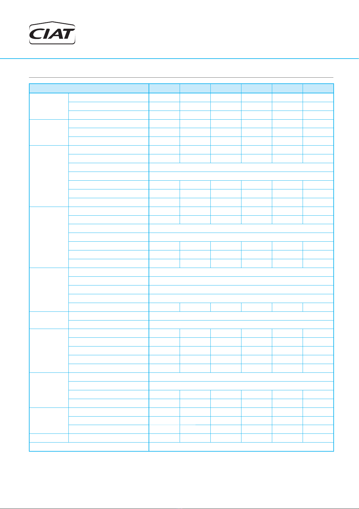
3. TECHNICAL CHARACTERISTICS (EN-14511-2013)
HCompact2 HA 55 65 80 90 120 160
Cooling
capacities
Cooling capacity (kW) 12,5 15,3 20,1 21,5 27,1 35,9
Power input (kW) 5,2 6,6 7,4 8,5 11,0 15,4
EER performance 2,38 2,30 2,70 2,53 2,47 2,33
Heating
capacity
Heating capacity (kW) 14,2 16,9 21,1 23,1 30,5 41,0
Power input (kW) 4,8 5,7 6,4 7,4 9,3 13,3
COP performance 2,93 2,96 3,29 3,13 3,28 3,10
Outdoor
circuit
fan
Nominal air flow (m3/h) 4.100 4.600 6.500 7.000 10.000 12.200
Available static pressure (mm.w.c) 9 9 10 10 12 12
Type Centrifugal
Number 1
Motor output (kW) 1,1 1,5 1,5 2,2 2,2 3,0
Power input (kW) 0,77 1,01 1,14 1,33 1,37 2,03
Speed (r.p.m.) 1.125 1.207 828 859 589 630
Indoor
circuit
fan
Nominal air flow (m3/h) 2.500 3.100 4.000 4.600 6.000 7.000
Available static pressure (mm.w.c) 5,0 5,0 6,2 6,2 6,2 7,5
Type Centrifugal
Number 1
Motor output (kW) 0,55 1,1 1,1 1,5 1,5 3,0
Power input (kW) 0,35 0,63 0,67 0,94 1,20 1,94
Speed (r.p.m.) 1.115 1.340 1.051 1.150 988 1.168
Compressor
Type Scroll
Compresor number 1
Circuit number 1
Oil type Copeland 3MAF 32cST, Danfoss POE 160SZ, ICI Emkarate RL 32CF, Mobil EAL Artic 22CC
Voulme of oil (l) 1,6 1,6 1,6 3,0 3,3 3,3
Electrical
characteristics
Electrical power supply 400 V / III ph / 50 Hz (±10%)
Power supply 3 Wires + Ground
Maximum
absorbed
current
Compressor (A) 15,0 19,0 19,0 22,0 29,0 35,0
Outdoor fan (A) 2,7 3,6 3,6 5,0 5,0 6,9
Indoor fan (A) 1,6 2,7 2,7 3,6 3,6 6,9
Control (A) 2,0 2,0 2,0 2,0 2,0 2,0
Total (A) 21,3 27,3 27,3 32,6 39,6 50,8
Refrigerant
Type R-410A
Global warming potential (GWP) 2.088
Charge (kg) 2,5 3,0 4,5 4,9 5,0 6,2
Environment impact (t CO2e) 5,2 6,3 9,4 10,2 10,4 12,9
Dimensions
Length (mm) 1.420 1.420 1.760 1.760 2.300 2.300
Width (mm) 1.065 1.065 1.414 1.414 1.820 1.820
Height (mm) 576 576 701 701 824 824
Weight (kg) 245 253 332 375 472 521
Ø Condensate evacuation 3/4”
Cooling capacity calculated in accordance withthe EN-14511-2013 standard given for indoortemperature conditions 27ºC, 50% RH and 35ºC outdoor temperature.
Heating capacity calculated in accordance with the EN-14511-2013 standard given for indoor temperature conditions 20ºC and 6ºC WB outdoor temperature.
Total power input by compressor and motorised fans under nominal conditions calculated in accordance with the EN-14511-2013.
Climatic warming potential of a kilogram of fluorinated greenhouse gas in relation to a kilogram of carbon dioxide over a period of 100 years.

HEAT PUMPS -AIR CONDITIONING - REFRIGERATION - AIR HANDLING - HEAT EXCHANGE - NA 12.65 D 5
Horizontal package air conditionners
HCompact2 HA
4. UNIT IDENTIFICATION
Allunits bear,legibly andindelibly, adata platelocated in aprime space,
as appears in the attached image. Check that this plate matches the
correct model.
Check the condition of the equipment upon delivery.
Check that the details on the label, the packing and the data plate
match the order.
If equipment has been damaged, or there is a shortfall in delivery,
notify accordingly.
V-220005
V-220004
5. SAFETY ADVICE
These units work with refrigerant gas R-410A. This fluid is used up to
a maximum service pressure of 42 bar.
Refrigerant leaks:
A periodical check must be performed for refrigerant gas leaks as
per Regulation (CE) Nº517/2014 over certain greenhouse effect
fluoride gases. Please, consult the frequency of checks in chapter of
“Maintenance”.
Important: The serial number must be used in all
communications regarding the unit.
Ref. Produit\Item Nbr Designation\Description
An.Year No Serie\Serial Nbr \ No Produit
Refrigerant kW Absorbee\Input kW Poids\Weight
Refrigerant kg Tension\Voltage Temper ature Maxi C
BP Mini PSM\MOP Intensité\Current A IP
HP Maxi PSM\MOP Int.. Kit Elect. No CE
30, av JeanFalconnier
01350 CULOZ
Tel : 33(0)4 79 42 42 42
Made in Spain
Refrigerant type
Low pressure
Model
Order Nbr
Weight in operation
Line voltage
High pressure
Manufacturing Nbr
Electrical kit current
To avoid any risk of accident during installation, commissioning or
maintenance, it is obligatory to take into consideration the following
specifications for the units: refrigerated circuits under pressure,
refrigerantpresence, electricalvoltage presenceand implantationplace.
Because of all of this, only qualified and experienced personnel can
perform maintenance tasks or unit repairs.
It is required to follow the recommendations and instructions
in the maintenance brochures, the labels, and the specific
instructions.
It is necessary to comply with the norms and regulations
in effect. It is recommended to consult the competent
authorities regarding the applicable regulations for users
of units or components under pressure. The characteristics
of these units or components are included on the plates of
characteristics or in the regulatory documentation provided
with the product.
The compressor and line surfaces can reach temperatures
above 100ºC causing burns to the body. In the same fashion,
under certain conditions these surfaces can reach very cold
temperatures that can cause freezing risks.
Use safety goggles and gloves on the job. Be careful with
sharp parts or elements in the unit.
Caution: Before intervening in the unit, verify that the main
power to the unit is cut off. An electric shock can cause
personal damage.
Note: In order to recycle these units follow the stipulations
of Directives (EC) No. 96/2002 and No. 108/2003 regarding
electrical and electronic equipment and the management of
the resulting waste.
In case of a leak:
- Toxicity:AccordingtoASHRAE34,R-410Abelongsto theA1/A1group,
i.e. with high safety both in the mix and also in the case of a leak.
- Although it is not toxic, in case of a leak to atmospheric pressure the
liquid phase evaporates. The resulting vapours are heavier than air
and can displace the technician local air. In case of an accidental
dischargeina closed enclosure, fansmust be used toeliminatesaid
vapours.
- Although the R-410Ais not flammable, when in contact with a flame
ohot spot itcandecompose in fluorhydricacid HF andfluophosgene
COF2highly toxic and corrosive.
- To detect leaks, an electronic leak detector, an ultraviolet lamp or
soapy water must be used. Flame detectors do not help.
Important: Immediately repair any refrigerant leak, using
a recovery unit specific for R-410A that avoids a possible
mixture of refrigerants and/or oils.
Components of the R-410A R-32 R-125
Chemical formula CH2F2 CHF2CF3
Weight ratio 50% 50%
Unitary global warming potential (GWP) 675 3.500
Global warming potential (GWP) 2.088

HEAT PUMPS -AIR CONDITIONING - REFRIGERATION - AIR HANDLING - HEAT EXCHANGE - NA 12.65 D
6
Horizontal package air conditionners
HCompact2 HA
7. LOCATION AND ASSEMBLING
The unit must be handled with care to avoid transport damage. Thus
we recommend:
- For transport in a container, one must be selected that has an easy
load and unload to the installation location.
- Do not dispose of the skids nor the packaging materials until the
machine is in its final location.
- The unit must be lifted and fixed with care and without inclination
(maximum inclination 15º), since it could harm its operation. Please
refer to the weight and the gravity centre coordinates of each model
stated in the following table.
- The unit is designed to be transported safely by using a forklift truck.
The forks of the forklift truck must ensure that the centre of gravity
of the unit remains within the forks, because a misbalance in the
transport may cause the unit to turn over and fall from the forklift
truck.
Checkalso that the length ofthefork entries, so that theentire
weight-bearing structure of the unit can be supported on the forklift
truck. This also prevents the possible introduction of the truck’s fork
into functional parts of the unit that may cause damage to the unit.
The standards and recommendations of the forklift truck must also
be respected with regards to the maximum load, inclination of the
panel, elevation of the load for transport, and, in particular, the
maximum speed.
6. TRANSPORT
- Finally, the unit must be freed from the skids so that the inserts
available for the silent-blocks can be accessed. Each skid is fixed
to the crossbar using M4 screws.
Z
X
Yskid fixing screws
HCompact2
HA
Weight
(kg)
M0000 assembly M1111 assembly
Centre of gravity (mm) Centre of gravity (mm)
X Y Z X Y Z
55 245 591 611 266 609 609 266
65 253 585 617 268 603 615 268
80 332 755 746 308 775 743 308
90 375 764 769 307 744 766 307
120 472 1.104 917 340 1.106 906 340
160 521 1.096 921 343 1.097 910 343
Assembling
Assembling
- These units can be installed on the floor or on a brick frame or steel
profile.
•
Foresee appropriate damping devices in these fixtures to ensure
that noise and vibration transmission is avoided.
Location designation
Beforemoving the unit, makesure that allpanelsare fastened inplace.
Lift and lower with care.
Whenchoosing the location,whatever may bethe selected fashion,the
following precautions have to be taken into consideration:
- It is mandatory to comply with norm UNE-EN 378-3 on Safety
and Environmental Requirements. Part 3: “In situ” installation and
protection to people.
- The area where the unit will be located must be perfectly accessible
forcleaning andmaintenance operations(checkminimum freespace
formaintenance).Leave enough space for air circulationaroundthe
unit.
- It is necessary to check that the structure supports the unit’s weight
(please see weight in the centre of gravity table)
(please see weight in the centre of gravity table).
• In the event of assembling directly on silent-blocks to the ground,
it is recommended that a template of the unit’s footprint with the
anchoring points of the silent-blocks be made.
• Withthe help of thecrane or the forklifttruck, the unitwillbe raised
to a sufficient height that the silent-blocks can be screwed into its
base. The 4 silent-blocks must remain oblique to the unit.
• M10 metric threads have been provided for their placement in
the supports indicated in the following section “Anchorage for
silent-blocks”.Ahex key 17 or Allen wrench 8 will be used for this
operation based on the type of screw used.
Thisimage shows howthesilent-block option thatcan be supplied
for this unit is fixed to the unit.
• Check that the unit is perfectly levelled.
Centre of gravity coordinates

HEAT PUMPS -AIR CONDITIONING - REFRIGERATION - AIR HANDLING - HEAT EXCHANGE - NA 12.65 D 7
Horizontal package air conditionners
HCompact2 HA
It can also be fixed to the ceiling using a threaded rod:
• Insert in the framework ceiling 4 threaded rods.
• Insert the rods through the holes
in the unit base (13 mm).
• Place the antivibration mounts,
insert a washer and turn the nuts
until the unit is well secured.
• If there is enough space between
the framework and the unit, a
rubber or neoprene plate can be
squeezed in.
• Check that the unit is perfectly
levelled.
Threaded rod
DETAIL
Buffer
Spar
Washer
Hexagon nut
HCompact2
HA A
(mm) B
(mm) Weight
(kg)
M000 assembly
Reactions in the supports (kg)
R1 R2 R3 R4
55 1.392 1.092 245 78 58 45 65
65 1.392 1.092 253 81 59 45 67
80 1.732 1.432 332 96 75 70 91
90 1.732 1.432 375 110 88 77 99
120 2.311 1.817 472 125 113 112 122
160 2.311 1.817 521 139 126 122 135
When selecting damping devices both the unit weight and reactions
in the supports must be taken in account and are featured in the
following table.
M10
A
B
R4
R2
R3
R1
Since it is an unit designed to work indoors with ducted supply and
return,bothin the indoorand the outdoor circuits,the following aspects
need to be considered as well:
- Ensure that the location of the supply and return grilles does not
generate air recirculation.
- Check that there are no obstructions in the air supply and return grille
slats due to being tightly closed.
- If in the indoor/outdoor circuit the air return is not ducted, it is
necessaryto foresee in theplenum formed bytheceiling, framework
and walls, adequately sized grids appropriate so that the circuit in
question aspires the return air.
Sound level
These units are designed to work with a low acoustic level. In any
case, the design of the installation the outer environment, the kind
of building for the noise transmitted in the air and the solid elements
for the vibration transmission must be taken into consideration for the
acoustic radiation.
If necessary, commission a study to an acoustic technician.
C) The sound pressure level of the unit, with the ducted return and
supply connections, measured at a distance of 5 metres, in open field,
directivity at 2 and 1.5 metres from the ground is:
B) The sound power level in the indoor fan outlet to be taken into
account for the silencer calculation:
A) The sound power level in the outdoor fan outlet to be taken into
account for the silencer calculation:
Note: The sound pressure level depends on the installation conditions
and, as such, is only indicated as a guide.
HCompact2 HA 55 65 80 90 120 160
dB(A) 80,5 82,7 74,4 76,3 83,5 83,3
HCompact2 HA 55 65 80 90 120 160
dB(A) 72,0 77,4 80,4 77,1 79,2 77,1
HCompact2 HA 55 65 80 90 120 160
dB(A) 69,3 71,6 69,4 70,8 70,7 71,2
Anchorage for silent-blocks
Minimum free space for commissioning and
maintenance operations

HEAT PUMPS -AIR CONDITIONING - REFRIGERATION - AIR HANDLING - HEAT EXCHANGE - NA 12.65 D
8
Horizontal package air conditionners
HCompact2 HA
V-220004
V-220005
Electronic control
• AVANT electronic control
All HCompact2 HA units have an AVANT electronic control as
standard from the factory comprised of a main board and a TCO
user terminal.
Optionally, this control can have a terminal for pGD1 maintenance
thatfacilitates the initial schedulingof the unit,themodification of the
operating parameters and the description of the alarms produced.
Note: For more detailed information on this control please refer to
the specific brochure.
Recommendations for the TCO thermostat installation
From the thermostat some of the unit operation aspects are
controlled: operation modes, setpoint, differential, timings...
Because of this, it is very important to chose an appropriate location
withintheroom since initis where the unit’scontrol probe islocated.
This probe must report about the environmental conditions of the
occupied area.
The thermostat must be fixed at a height of 1.5 m y all possible
interferences must be avoided: sun, outdoor air, internal heat
sources... Mount the thermostat to the wall using the bracket, do not
leave it hanging from the wire or embedding it in the wall.
Electric
panel
Power supply inputs
8. CHECKING BEFORE COMMISSIONING
Electrical Connections
Note: Under no circumstance should the unit be started without having read the brochure completely.
Installation norms
To have electrical power to the unit: wire intake, conductor section and
theircalculations, protections, etc...,ask theinformationprovided inthis
document(refer to technicalcharacteristictable), the electricalscheme
included with the unit and norms in effect that regulate the installation
of air conditioning units and electrical receivers.
Verify that electrical power supply corresponds to the one on the data
plate and that the voltage remains constant according to the stipulated
range.
Check that the electrical connections are correct and tight
(an electrical diagram is included with each unit, along with
its legend).
Note:All connections in the site are the responsibility of the
installer. These connections are always made as per the
current regulation.
To prevent electricalshocks,make all electrical connections
before energizing the unit. Check that the automatic switch
is closed. Omitting this can cause personal damage. Make
theground connectionbefore anyother electricalconnection.
The installer must fix line protection elements according to
the effective legislation.
Connection chart
1
2
3
4
5
6
Outdoor
air circuit
Indoor
air circuit
pGD1
TCO user
terminal
maintenance
terminal (opt.)
No. Description 55 to 160
1Main power supply 400 III (±5%) 3 + GND
2TCO user terminal connection
2 wires for power supply
230V + 1 shielded cable
for communication type
AGW20 / 22 (1 braided pair
+ drainwire + shielding)
3pGD1 maintenance terminal
connection (optional) telephone cable 6 wires
standard (RJ12 connector)
4Remote off/on (optional) 2 wires
5Main alarm signal (optional) 2 wires
6Safety electrical heaters (optional) 2 wires
The same power supply used for powering the control board must
also be used for powering the terminal.

HEAT PUMPS -AIR CONDITIONING - REFRIGERATION - AIR HANDLING - HEAT EXCHANGE - NA 12.65 D 9
Horizontal package air conditionners
HCompact2 HA
Pulley and belt adjustment
Both for the indoor circuit motorfans as well as the outdoor circuit are
coupled by pulleys and belts.
Pulleys must stay on the same plane
Tensor
screw
Pulley
screws
Taper pin
In this type of fans, the following must be taken into considerations:
- The pulleys must be on the same plane, so it is important to check
them with the help of a ruler or a laser aligner.
- In case they are not aligned, remove the pulley screws, remove the
pulley and, after removing the hub pin, it can be slided over the axle
(thisactioncan be performed bothinthe motor as wellas in the fan).
- After fixing the pulleys on the same plane, the belt tension is made
by tightening the tensor screw.
- The belt tension must be checked after 24 hours of motor operation.
Attention: Beforeperforming these operations,itis necessary toverify
that the unit is disconnected from mains.
These units can incorporate an auxiliary electric panel for optional
components such as: transformer for power supply without neutral,
transformerfor damperof condensationpressure controlanddifferential
pressostats for dirty filters and control of air flow.
Damper
transformer Pressostat for
dirty filters Pressostat for
flow control Transformer for power
supply without neutral
Auxiliary
electric
panel
Interchangeable position of air supply
Bothin the indooraircircuit aswellas the outdoorcircuit, the supplyfan
can be located in either of the two positions indicated in the following
illustration, since both panels are easy interchangeable. This means it
can be fitted on-site in accordance with the installation requirements.
Fan panel is fixed to pillars inside the machine, using 4 sheet-metal
screws Ø 3,5mm. The motor-fan assembly is fixed to the base of the
machine with 4 rivet nut M8.
Fixation to the base Access panelSupply panel
- Before commissioning, check the blade rotation direction and that
the axis turns without strokes nor vibrations
- Once running, check the operation conditions: pressures, flows and
consumptions.
- The coupling of characteristic bends of the fan and the room is
very important, so that the flows and pressures provided to the duct
network are as required.
Checks at centrifugal fans

HEAT PUMPS -AIR CONDITIONING - REFRIGERATION - AIR HANDLING - HEAT EXCHANGE - NA 12.65 D
10
Horizontal package air conditionners
HCompact2 HA
Indoor circuit Outdoor circuit
Siphon installation norms
- Check that the condensate outlet is not clogged.
- All water drain tubes must be provided with a siphon to avoid bad
smell and water spills.
Perform the assembly as per the scheme of the attached starting
diagram:
Pan in overpressure: it is installed to avoid the access through the
drain tubing of bad smells.
Pan in underpressure: besides the previous application, water must
be sucked from the pan:
• Forthe correct siphon design,the “A” heightmustbe at leasttwice
that of the underpressure where the condensates pan is placed.
• Thedrain tubingmust beslightlysloped toease circulationtowards
the drain.
• Theoriginaldiameter of thetubemust be respected. Noreduction
can be made.
A
Condensates pan
in depression
A
Siphon drain
Slight slope
5/1000
To drainage
Check the connection tightness.
CONNECT SIPHON
METTRE SIPHON
PONER SIFON
V220014
Interchangeable position of air return
Interchangeable panels
Both in the indoor air circuit as well as the outdoor circuit, the return
panel can be located in either of the two positions indicated in the
following illustration, since both panels are easy interchangeable.
This means it can be fitted on-site in accordance with the installation
requirements.
The panel with the return grille is fixed to pillars inside the machine,
using 4 sheet-metal screws Ø 3,5mm.
Access
panel Return
panel
The air supply and return ducts must be calculated in accordance with
the rated flow and the unit's available pressure(refer to the technical
characteristics table). The duct calculation and design must be made
by qualified technical personnel.
Itis advisableto takeintoconsideration thefollowing recommendations:
- Bendsinthefandischargesupplymustbeavoided.Itisrecommendable
to have a straight section of duct measuring approximately 1 metre.
If it is not possible, they must be as smooth as possible, using indoor
deflectors when the duct is of large dimensions.
- When making the ducts, direction sharp changes must be avoided
sincetheycan generate occasional pressuredrops,which affectthe
availablepressure and theflow.The locationofsupply andaspiration
grilles must be studied carefully to avoid the air recirculation and the
transmission and generation of noises to the interior.
- Flexible connections must be made between the ducts and the unit
that avoid the noise and vibration transmission.
- No matter the type of ducts type to use, they must not be composed
ofmaterials that propagatefirenor expeltoxicgases intheevent of a
fire.The internalsurfaces must besmoothand should notpollute the
air that circulates within them. In any case, the effective legislation
about this issue must be respected.
Caution: These units are designedto be connected toa duct
network. If the indoor circuit outlet fan is accessible from a
particular point in the duct network, the installer must fit a
protectionmeshinthedischarge asperthecurrentregulation.
Air ducts connections
Condensate drain connection
All models are provided with two condensates drain pans, one in the
indoorcircuit and anotherone in theoutdoor
circuit,with asphaltic paint andindependent
drains. Female drain joint, made of bronze,
gas thread 3/4".
Do not connect the drains, make the siphons independent.

HEAT PUMPS -AIR CONDITIONING - REFRIGERATION - AIR HANDLING - HEAT EXCHANGE - NA 12.65 D 11
Horizontal package air conditionners
HCompact2 HA
9. SAFETY ELEMENTS
Automatic switch in the control circuit
Magnetothermal switch that protects the operation circuit against
continuous surges as well as against high currents of short duration
(short circuits).
Safeties at the compressor
The scroll type compressor that these units as standard have the
following safeties:
- Non-return valve built into the compressor.
- Temperature probe forthedischarge from the compressorto protect
the unit with discharge temperatures greater than 135ºC.
Clogged filter detector (optional)
Differentialpressostatforindication ofmaintenance to filters.Automatic
reactivation. This pressostat is installed in the auxiliary electric panel.
Air flow control (optional)
Differentialpressostat thatmeasures the flowvariation intheair supply.
Thisallowsthe detection of fanbelt breakages, since thefanrelay only
detects operating faults that have arisen in the motor. This pressostat
is installed in the auxiliary electric panel.
This safety device is compulsory in units with electrical heaters.
Auxiliary
electric panel Pressostat for
dirty filters
Pressostat for
flow control
High pressure pressostat
Connected to the compressor discharge, it will stop its operation when
the pressure at that point reaches the setpoint. It disconnects at 42 bar
and it is automatically reactivated.
Low pressure pressostat
When connected to the intake compressor, it will stop operating
when the pressure at this point drops below the tare value (caused
by obstructions in the circuit, excessive dirt in the filters, fan stop or
ice formation in the evaporator). It disconnects at 2 bar and resets
automatically.
Magnetothermals for line protection
They are located at the beginning of the power lines of the compressor
and motorfans to protect them.
Main door switch
By using a mechanical device, it impedes access to the electric panel
when the unit is with voltage.
Anti-fire safety
Withthe return probeoption, the electroniccontrol can activatea safety
anti-fie that, when the temperature of the air of comeback overcomes
them 60ºC (for defect), the unit stops.
This one will not be able to work again until the temperature does not
descend below 40ºC.

HEAT PUMPS -AIR CONDITIONING - REFRIGERATION - AIR HANDLING - HEAT EXCHANGE - NA 12.65 D
12
Horizontal package air conditionners
HCompact2 HA
Access for maintenance:
The frame has access designed from the right side for maintenance.
To access the electrical
heaters, the screws that
fasten the frame side panel
mustbe unscrewed asshown
in the illustration.
Access panel
Inordertoremovetheelectrical
heaters the power supply
cables must be disconnected
from the terminal board and
the hose taken out.
Rail
Then, unscrew the screw that fastens the resistor frames and take out
by the rail, as shown in the following images.
Servomotor
Damper
10. OPTIONS
Condensation pressure control
This control is advisable for units that work in cooling with an outdoor
temperature below 15º C.
In units with centrifugal fan a check is performed per damper in the
fan outlet.Aservomotor opens or closes the damper depending on the
proportional signal 0-10V received from the electronic control system.
Electrical heater
- The auxiliary electrical heaters are ready for operation in one power
stage.
- Theheaters acquired with theunit will beincorporatedto it modifying
the electric panel in the factory, so that it is compatible with the
electronic control.
- The electrical heaters requested for units already shipped will be
sent in a kit, and the installer will need to assemble the elements
required for the operation of the unit and for compliance with the
legal regulations that are applied to the modified unit with regard to
safety.
Note: with this option, the air flow controller is included.
Hose
Electrical
heaters
Safety
thermistors
Kit assembly:
When the frame with the heaters is provided in a kit, follow the steps
below for connecting it:
Step 1: place the frame on the panel to set the hole positions that will
fix the frame to the panel (use the top left-hand corner as a guide).
Reference
corner
Frame holes

HEAT PUMPS -AIR CONDITIONING - REFRIGERATION - AIR HANDLING - HEAT EXCHANGE - NA 12.65 D 13
Horizontal package air conditionners
HCompact2 HA
Holefor the power supply
Another hole must also be
drilled to connect the hose
to the electric power supply.
Step2: fastenthe frameto the
panelwith selfturning screws.
Step 3: insert the hose
through the hole made for
the connection in the electric
panel.
Note: The connection of the
necessary elements for the
adequacy to the handling of
theunit mustbe performedby
the installer.
Access panel
Step 4: close the access
panel. The outlet is ready for
ducting.
Filters
These units can substitute the filtering mesh that the units include
regularly with G4 rating, mounted on the same frame.
Optionally these teams can incorporate, besides the gravimetric filter
G4, an creased opacimetric filter with F7 rating. For this combination
offilters,the filter holder profileisdifferent. Itis wider than the standard
in 50 mm
Filter holder profile
Frame with
gravimetric filter
Opacimetric
filter rail
Frame with
opacimetric filter
Gravimetric
filter rail
Filter removal:
These frames with the gravimetric and opacimetric filter can be
extracted easily by both sides.

HEAT PUMPS -AIR CONDITIONING - REFRIGERATION - AIR HANDLING - HEAT EXCHANGE - NA 12.65 D
14
Horizontal package air conditionners
HCompact2 HA
11. COMMISSIONING
- When starting the compressor, check the undercooling and
overheating and thus verify if the refrigerant
chargeis appropriateto theoperating conditions.
To adjustthe refrigerantcharge, aschrader valve
is available on the liquid line.
- Verify the absence of any leaks of the refrigerant.
- Check the unit operation and verify the safety elements.
- Allthestandardmodelsareequipped
with a scroll type compressor and
have a phase control relay. Verify
thattheyturn in the correctdirection
and, if not, reverse the power wires.
R 410A
COMPRESOR SCROLL.
COMPROBAR SENTIDO DE GIRO
COMPRESSEUR SCROLL.
VÉRIFIER LE SENS DE ROTATION
SCROLL COMPRESSOR.
CHECK SENSE OF ROTATION
Operational checks
Check the unit operation by verifying the electronic control and the
safety elements.
It is also recommendable to create a report, taking note of the date,
which includes the following information: the nominal voltage, current
absorbed by the compressors, fans and other electrical components,
significant temperatures in the cooling circuit (see table below) and
other aspects considered interesting such as alarms detected by the
electronic control of the unit. The recording of these parameters whilst
the unit is running allows controlling the installation performance and it
isthe bestpossible waytoavoid breakdownssince theanalysis ofthese
data makes early detection of anomalies possible or the provision of
the necessary means available to ensure that they do not take place.
Possible problems at commissioning
All indications given in this brochure must be respected and
complied with to guarantee a correct operation of the units.
Next, several possible operation problems are stated which could
happen if the conditions of the commissioning are not appropriate.
- Airflowlack:very highdifferencesbetween inletand outlet,originated
by a high pressure drop in the ducts, or by other causes that impede
the correct air circulation.
- Air recirculation in the unit, originated by some obstacle in the air
aspiration or outlet.
- Noise problems because of excessive air flow in the grille.
- Water overflowing to the pan problems, originated by an excessive
flow,an incorrectsiphon installation orbecause a defectiveunit level.
- Refrigerantcircuit humidityproblem,because ofanincorrect vacuum
realization.
Checks prior to commissioning
- Itisadvisable to make acomplete sketch of theinstallationincluding
thelocation of the unitand all the componentsused. Thiswill be very
helpful for maintenance and repairs to the installation.
- Check that the electrical power supply matches the unit voltage and
that its value lies within acceptable limits.
- It must also be verified that the electric installation has been carried
out according to the electric wiring diagram provided with the unit
(consult the chapter on “Checking before commissioning”).
- Once the above verifications have been carried out, the control
circuit is supplied with voltage by the automatic control switch. It is
advisable to leave with voltage the compressor crankcase heater
for 24 hours before starting the compressor.
WICHTIG: WIEDERBEHEIZUNG DER
OLWANNE
IMPORTANT: CRANKCASE HEATING
IMPORTANT: SURCHAUFFE CARTER D’HUILE
IMPORTANTE: RISCALDARE IL CARTER
DELL’OLIO
IMPORTANTE: RECALENTAMIENTO DE
ACEITE DEL CÁRTER
KOENNEN.
TO ALLOW THE COMPRESSOR(S) STARTING
AU PREMIER DÉMARRAGE OU APRÈS UNE ABSCENCE
TENSION 24 HEURES AVANT D’AUTORISER LE
DÉMARRAGE DU(DES) COMPRESSEUR(S).
AL PRIMO AVVIAMENTO U DOPO UNA INTERRUZIONE
PROLUNGATA DELLA ALIMENTAZIONE ELETTRICA,
LASCIARE LA MACCINA SOTTO TENSIONE PER 24 ORE
PRIMA DI AUTORIZZARE L’AVVIAMENTO DEL(DEI)
COMPRESSORE(I).
ANTES DEL PRIMER ARRANQUE O DESPUÉS DE UNA
AUSENCIA DE CORRIENTE POR UN LARGO PERIODO DE
TIEMPO, CONVIENE QUE LA UNIDAD ESTÉ CONECTADA
UN MÍNIMO DE 24 HORAS.
BEIDER ERSTEN INBETRIEBSETRUNZ ORDER NACH EINER
LANGEN STROMUNTER-BRECHUNG BRINGEN SIE DIE
MASCHINE UNTER SPANNUNG 24 STRUNDERLANG
BEVOR SIE DEN(DIE) KOMPRESSOR(EN) EINSCHALTEN
FOR THE FIRSTSTART OR AFTER ALONG TIME OUT OF
VOLTAGE PUT THE MACHINE ON LIVE 24 HOURS BEFORE
DE COURANT PROLONGÉE, METTRE LA MACHINE SOUS
Cooling MODE Heating MODE
Compr.
Aspiration pressure bar
Compr.
Aspiration press. bar
Aspiration temp. (1) ºC Aspiration temp. (1) ºC
Condens. pressure bar Condens. pressure bar
Condens. temp. (2) ºC Condens. temp. (2) ºC
Air
condens.
Gas inlet temp. ºC
Air
evap.
Liquid inlet temp. ºC
Liquid outlet temp. (3) ºC Gas outlet temp. (4) ºC
Air inlet temp. ºC Air inlet temp. ºC
Outdoor temp. ºC Outdoor temp. ºC
Air outlet temp. ºC Air outlet temp. ºC
Air
evap.
Air inlet temp. ºC
Air
condens.
Air inlet temp. ºC
Air outlet temp. ºC Air outlet temp. ºC
Liquid inlet temp. ºC Gas inlet temp. ºC
Evap. outlet temp. (4) ºC Liquid outlet temp. (3) ºC
Undercooling (2) - (3) ºC Undercooling (2) - (3) ºC
Overheating (4) - (1) ºC Overheating (4) - (1) ºC

HEAT PUMPS -AIR CONDITIONING - REFRIGERATION - AIR HANDLING - HEAT EXCHANGE - NA 12.65 D 15
Horizontal package air conditionners
HCompact2 HA
Gravimetric
filter rail Opacimetric
filter rail
Filter holder
profile
12. MAINTENANCE
Access to the inside of the machine by all panels. These
access panels are fixed with rivet nuts M4.
Centrifugal fan
- Verify that the turbine and the motor remain clean.
- Foresee having a spare belt set for the fans.
- The motors and the fans have bushings that have been lubricated
and sealed and, thus, do not need further lubrication.
Theminimalmaintenance operations andtheirperiodicity will be made
according to the national regulations.
Any intervention on the electric cooling components must be made by
a qualified and authorized technician.
Technicians who intervene with the unit must use the necessary safety
equipment (gloves, goggles, insulating clothing, safety shoes, etc.).
Furthermore, if working around sources of significant noise, we
recommend the use of noise-dampening headgear.
V-220004
Caution: Before intervening in the unit, cut off main power.
V-220005
Condensate drain pans
- Check that the condensate pans of the outdoor and indoor circuits
are clean. There should be no stagnant water.
- Check that the drain is not clogged.
- Cleaning of the pan can be done with water and non-abrasive
detergent.
Servomotor (optional)
In units with a condensation pressure regulation damper (in the STD
version), it is advisable to check the state of the servomotor.
Indoor circuit
condensate drain
Air filters
The frames with the gravimetric and opacimetric filter can be extracted
easily by both sides.
- Clean usually. Depending on the installation conditions, the filter
aspect must be examined to define the cleaning periodicity.
- Gravimetric filters. Cleaning the filtering mesh can be done with a
household vacuum cleaner, or else by submerging it in water.
- Creased opacimetric filters It is necessary to replace them. Foresee
replacement.
Outdoor circuit
condensate drain
Indoor
circ. pan Indoor
circ. coil Outdoor
circ. pan Outdoor
circ. coil
General recommendations:
- Do not lean on the unit.A platform must be used to work on a level.
- Do not lean on the copper refrigerant tubes.
- Keep the unit clean.
- Keep the space surrounding the unit clean and cleared in order to
avoid accidents and ensure the proper ventilation of the coil.
- Perform a visual (remains of water or oil below or around the unit)
and auditory inspection of the entire installation.
- In general, a corrosion control must be performed on the metallic
parts of the unit (frame, bodywork, exchangers, electric panel, etc.).
- Check that the insulation foam is not unstuck or torn.
- All the electric connection states must be checked as well, as well
as the air tightness of the different circuits.
Next, some recommendations are stated to perform the cleaning of
the unit's components:
Air coil
- Check that the coil is free from dust and grease.
- Cleaning the accumulated dust on the coil can be performed with
a vacuum cleaner perpendicular to the fins or with a low-pressure
water cleaner. Grease can be removed with water with degreaser.
Do not put stress on the fins as they could deform.
Use safety gloves for this task. Take care with the sharp
parts of the coil.

HEAT PUMPS -AIR CONDITIONING - REFRIGERATION - AIR HANDLING - HEAT EXCHANGE - NA 12.65 D
16
Horizontal package air conditionners
HCompact2 HA
Oil
Oils used for cooling machines do not post any threat to one’s health
if used while following the usage guidelines:
- Avoid any unnecessary manipulation of the elements covered in oil.
Use protection creams.
- Oilsareflammable and mustbe stored and handledwith precaution.
“Disposable” rags or towels used for cleaning must be kept away
Compressor
In the case of compressor replacement:
- Disconnect the unit from power supply.
- Completely empty the load of refrigerant using a specific recovery
unit for R-410A
- Disconnect electrically the compresor.
- Carefully unscrew the suction and discharge piping.
- The compressor is fixed onto the platform with 4 screws Ø 8 mm.
Unscrew the fixings.
- Placethe newcompressor andcheckthatithasasufficientoilcharge.
Warning: when tightening the compressor screws, the maximum
torque to be applied is:
• Models 55, 65, 80: 11 Nm.
• Models 90, 120, 160: 15 Nm.
If a torque wrench is not available, tighten them until noticing
resistance,then tightenthe screwsby turningthem 3/4of arevolution.
- Screw the suction and discharge piping.
- Connect the compressor in accordance with the circuit diagram.
- Make vacuum and next, reload the gas into the unit according to
load data provided in the technical characteristics table and in the
unit’s data plate.
from open flames and must be discarded by using the appropriate
procedure.
- Jugs must be kept closed.Avoid using oil from an already-open jug
kept in poor conditions.
Both the oil type as well as the volume needed for each model are
stated in the characteristics table in chapter 3.
- Check the oil level and aspect. In case of a colour change, check
the oil quality using a contamination test.
- Inthe caseof thepresenceof acid,water ormetallic particles,replace
the affected circuit oil, as well as the dehydrant filter.
- In the event of an oil charge change, only new oil will be used, which
will be identical to the original oil and taken from a jug tightly closed
until the moment of the charge.
Dehydrating filter Compressor
Dehydrant filter
- Thefilter functionisthe preservethecooling circuitcleanand without
humidity, neutralizingthe acidsthat canbefound inthe coolingcircuit.
Verifydirt measuringthedifferencein temperature atthe tubing level,
at the inlet and at the outlet of the dehydrant.
- If necessary, replace.
Refrigerant
Only qualified personnel must perform a periodic tightness control, in
accordance with the regulation (CE) Nº 517/2014.
- Thefrequency of checksisno longerrelatedto theloadof refrigerant
but to its global warming potential:
Load kg x GWP = t CO2e
Carbondioxide equivalency (tCO2e ) isaquantity thatdescribes,for
agiven mixtureand amountofgreenhouse gas,the amountin tonnes
of CO2 that would have the same global warming potential (GWP).
Please,consult dataof carbondioxideequivalency (tCO2e) provided
in the technical characteristics table (chapter 4).
- Operators shall ensure that the unit is checked for leaks ad minima
according to the following frequency:
• t CO2e < 5 ............not subjected
• t CO2e 5 to 50 ......every year
• t CO2e 50 to 500 ...every 6 months
• t CO2e > 500 .........every 3 months
- Wherealeakage detection system has been installedthefrequency
of checks is halved.
Note:Never forget thatthe cooling systemscontain liquids andvapours
under pressure. The service pressure of R-410Ais approximately 1.5
higher than that of R-407C.
- All necessary precautions must be taken during the partial opening
of the cooling circuit. This opening entails the discharge of a certain
amount of refrigerant to the atmosphere. It is essential to limit this
quantity of lost refrigerant to a minimum by pumping and isolating
the charge in some other part of the circuit.
- The refrigerant fluid at low temperature can cause inflammatory
injuriessimilar to burnswhen contacting theskin or eyes.Alwaysuse
safety goggles, gloves, etc. when opening ducts that may contain
liquids.
- The refrigerant in excess must be stored in appropriate containers
and the amount of refrigerant stored at the technical rooms must be
limited.
- Refrigerant barrels and deposits must be handled with precaution
and visible warning signs must be placed to attract attention over
the risks of intoxication, fire and explosion linked to the refrigerant.
- At the end of its useful life, the refrigerant must be retrieved and
recycled as per the current regulations.

HEAT PUMPS -AIR CONDITIONING - REFRIGERATION - AIR HANDLING - HEAT EXCHANGE - NA 12.65 D 17
Horizontal package air conditionners
HCompact2 HA
13. CONTROL AND ANALYSIS OF BREAKDOWNS
Symptom Cause Solution
Evaporation pressure very high in relation with
the air inlet a) Charge excess
b) High air temperature
c) Compressor aspiration not air tight
d) Cycle reversing valve in middle position
a) Collect refrigerant
b) Verify overheating
c) Verify compressor state and replace
d) Check that the valve is not clogged. Replace if
necessary
Very low condensation pressure a) Gas lack
b) Compressor aspiration not air tight
c) Cycle inversion valve in middle position
d) Liquid circuit plugging
a) Search for leaks, complete charge
b) Verify compressor state and replace
c) Check that the valve is not clogged. Replace if
necessary
d) Verify the dehydrating filter and expansion valve
Condensation pressure very high in relation to the
air outlet, high pressostat cutoff a) Insufficient air flow
b) Air inlet temperature very high
c) Dirty condenser (does not exchange)
d) Much refrigerant charge (flooded condenser)
e) The condenser fan is broken down
f) Air in the cooling circuit
a) Verify the air circuits (flow, filter cleanliness...)
b) Verify the control thermostat readjustment
c) Clean it
d) Collect refrigerant
e) Repair
f) Make vacuum and load
Evaporation pressure too low (low pressostat
cutoff) a) Low flow in evaporator.Air recirculation
b) Frozen evaporator
c) Liquid line as different temperatures at filter inlet
and outlet
d) Gas lack
e) Very low condensation pressure
f) Evaporator fan broken down
a) Verify the air circuits (flow, filter cleanliness...)
b) Verify defrost
c) Replace filter
d) Search for leaks, complete charge
e) Temperature of air or water in condenser very
low (air or water flow very high), adjust flow
f) Repair
Compressor does not start, does not make noise
(humming) a) No power
b) The contacts of a control element are open
c) Timing of anti cycle short does not allow the
starting
d) Open contact
e) Contactor coil burnt
f) Indoor Klixon open
a) Check differential, magnetothermals
b) Verify the safety chain of the electronic control
c) Verify electronic control
d) Replace
e) Replace
f) Wait for reactivation, verify intensity absorbed
Compressor does not start, motor sounds
intermittently a) Electrical power supply very low
b) Power cable disconnected a) Control line voltage and locate voltage drop
b) Verify connections
Repeated compressor starts and stops a) Because of high pressure
b) Control differential too short (short cycle)
c) Gas lack, cutoff because of low pressure
d) Dirty or frosted evaporator
e) The evaporator fan does not work, cuts off the
low pressostat
f) Expansion valve damaged or clogged by
impurities (cuts off low pressostat)
g) Dehydrating filter clogged (cuts off low safety)
a) Verify charge
b) Increase differential
c) Search for leak, reload unit
d) Clean, verify evaporator air circuit
e) Replace or repair
f) Replace, as well as filter
g) Replace
The compressor makes a noise a) Loose attachment
b) Oil lack
c) Compressor noise
a) Fix
b) Add oil to recommended level
c) Replace
Noisy operation a) Unit installed without antivibration protection a) Place base over shock absorbers
Cycle reversing is not carried out:
- No defrosting
- Does not change winter - summer cycles
a) Electrical fault
b) Inversion valve coil defective
c) Defrost method not working
d) Cycle inversion valve in middle position
e) Control fault
a) Locate and repair
b) Replace
c) Verify parameters
d) Tap with running compressor. Replace if
necessary
e) Locate and repair

HEAT PUMPS -AIR CONDITIONING - REFRIGERATION - AIR HANDLING - HEAT EXCHANGE - NA 12.65 D
18
Horizontal package air conditionners
HCompact2 HA
Notes:


This manual suits for next models
14
Table of contents
Other CIAT Heat Pump manuals

CIAT
CIAT SC Series User manual

CIAT
CIAT AQUACIAT CALEO TD 80 User manual

CIAT
CIAT AQUACIAT POWER ILD Series User manual

CIAT
CIAT Ereba He Series User manual

CIAT
CIAT 7321648 Operating manual

CIAT
CIAT µConnect User manual

CIAT
CIAT CONDENCIAT CD series Guide

CIAT
CIAT AQUALIS 20 Guide

CIAT
CIAT COADIS LINE 600 User manual

CIAT
CIAT CONDENCIAT CL2 User manual
Popular Heat Pump manuals by other brands

Carrier
Carrier 38BYC Series Product data

Sinclair
Sinclair GSH-IRAD user manual

Dimplex
Dimplex BWP 30 HS Installation and operating instructions

Bryant
Bryant 604B 024-060 Installation, Start-Up and Service Instructions

McQuay
McQuay Templifier Installation data

Carrier
Carrier 48VR Owner's information manual