1 - INTRODUCTION
Prior to the initial start-up of the Aquaciat Caléo™ TD units, the
people involved should be thoroughly familiar with these
instructions and the specic project data for the installation site.
The Aquaciat Caléo™ TD heat pumps are designed to provide
a very high level of safety and reliability making installation,
start-up, operation and maintenance easier and more secure.
They will provide safe and reliable service when operated within
their application range.
They are designed for a theorical operating life of 15 years based
on loads profile defined within the applicable Ecodesign
regulations
Beyond this period, the manufacturer recommends to proceed
to a fatigue prevention survey on the refrigerating circuit
conducted by an operator qualied for the control of pressure
equipment. It is recommended to repeat this check every 5 years.
This control does not replace the requirements of applicable
national regulations.
The procedures in this manual are arranged in the sequence
required for machine installation, start-up, operation and
maintenance.
Be sure you understand and follow the procedures and safety
precautions contained in the instructions supplied with the
machine, as well as those listed in this guide, such as: protective
clothing such as gloves, safety glasses, safety shoes and
appropriate tools, and suitable qualications (electrical, air
conditioning, local legislation).
To nd out, if these products comply with European directives
(machine safety, low voltage, electromagnetic compatibility,
equipment under pressure, etc.) check the declarations of
conformity for these products.
1.1 - Check equipment received
-Inspect the unit for damage or missing parts. If damage is
detected, or if shipment is incomplete, immediately le a claim
with the shipping company.
-Conrm that the unit received is the one ordered. Compare
the name plate data with the order.
-The name plate is attached to the unit in two locations:
• on the outside on one of the unit sides
• on the control box door on the inside
-This shows the following information:
• Model number - size
• CE marking
• Serial number
• Year of manufacture and pressure and leak tightness test date
• Refrigerant used
• Refrigerant charge per circuit
• PS: Min./max. allowable pressure (high and low pressure
side)
• TS: Min./max. allowable temperature (high and low pressure
side)
• Pressure switch cut-out pressure
• Unit leak test pressure
• Voltage, frequency, number of phases
• Maximum current drawn
• Maximum power input
• Unit net weight
-Conrm that all accessories ordered for on-site installation
have been supplied, are complete and undamaged.
The unit must be checked periodically, if necessary
removing the insulation (thermal, acoustic), during its whole
operating life to ensure that no shocks (handling accessories,
tools, etc.) have damaged it. If necessary, the damaged parts
must be repaired or replaced. See also chapter “Maintenance”.
1.2 - Installation safety considerations
After the unit has been received, when it is ready to be installed
or reinstalled, and before it is started up, it must be inspected for
damage. Check that the refrigerant circuits are intact, especially
that no components or pipes have shifted or been damaged (e.g.
following a shock). If in doubt, carry out a leak tightness check. If
damage is detected upon receipt, immediately le a claim with the
shipping company.
This machine must be installed in a location that is not accessible
to the public and protected against access by non-authorised
people.
Do not remove the skid or the packaging until the unit is in
its nal position. These units can be moved with a fork lift
truck, as long as the forks are positioned in the right place
and direction on the unit.
The units can also be lifted with slings, using only the
designated lifting points marked on the unit (labels on the
chassis and a label with all unit handling instructions are
attached to the unit tank - refer to chapter 2.4).
Use slings with the correct capacity, and always follow the
lifting instructions on the certied drawings supplied for
the unit.
Safety is only guaranteed, if these instructions are carefully
followed. If this is not the case, there is a risk of material
deterioration and injuries to personnel.
These units are not designed to be lifted from above.
DO NOT COVER ANY PROTECTION DEVICES.
This applies to fuse plugs and relief valve (if used) in the
refrigerant or heat transfer medium circuits. Check if the
original protection plugs are still present at the valve outlets.
These plugs are generally made of plastic and should not
be used. If they are still present, please remove them. Install
devices at the valve outlets or drain piping that prevent the
penetration of foreign bodies (dust, building debris, etc.)
and atmospheric agents (water can form rust or ice). These
devices, as well as the drain piping, must not impair
operation and not lead to a pressure drop that is higher than
10% of the control pressure.
Ensure that the valves are correctly installed, before
operating the unit.
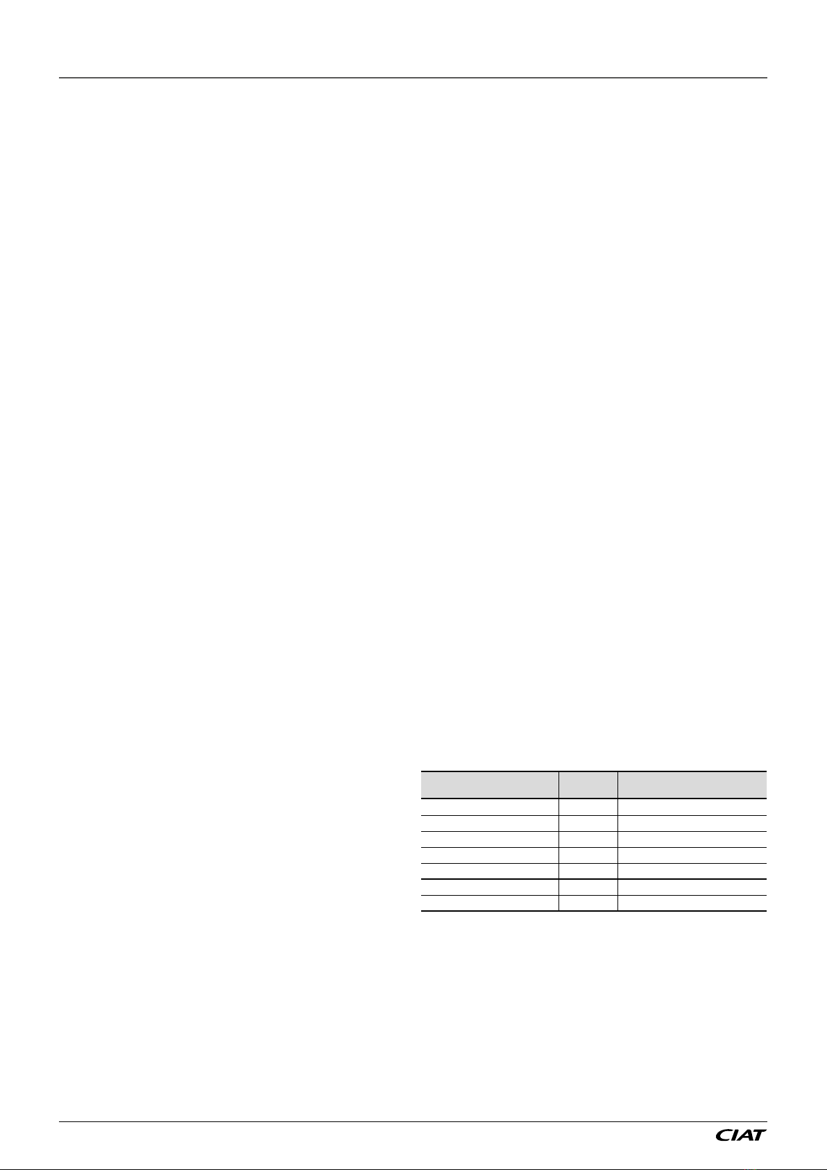
Classication and control
In accordance with the Pressure Equipment Directive and
national usage monitoring regulations in the European
Union the protection devices for these machines are
classied as follows:
Safety
accessory(1)
Over pressure protection in case
of an external re(2)
Refrigerant side
High-pressure switch x
External relief valve(3) x
Rupture disk x
Fuse plug x
Heat transfer uid side
External relief valve (4) (4)
(1) Classied for protection in normal service situations.
(2) Classied for protection in abnormal service situations. These accessories
are sized for res with a thermal ow of 10kW/m². No combustible matter
should be placed within 6.5m of the unit.
(3) The instantaneous over-pressure limitation to 10% of the operating pressure
does not apply to this abnormal service situation. The control pressure can
be higher than the service pressure. In this case, either the design temperature
or the high-pressure switch ensures that the service pressure is not exceeded
in normal service situations.
(4) The classication of these relief valve must be made by the personnel that
completes the whole hydraulic installation.
Do not remove these valves and fuses, even if the re risk
is under control for a particular installation. There is no
guarantee that the accessories are re-installed if the
installation is changed or for transport with a gas charge.
AQUACIATCALÉO™ TD EN-4