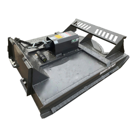
CID SBC 14-20 GPM User manual

SAFETY RULES | OPERATING INSTRUCTIONS | MAINTENANCE PROCEDURES
SBCSBCSMAN01
AUGUST 2021
OWNER’S MANUAL
SWING BOOM
CUTTER
MODEL SERIES
17-30 GPM17-30 GPM
14-20 GPM14-20 GPM
SBCNS
SBC

DEALER INFORMATION
PURCHASE DATE:
DEALER NAME:
ADDRESS:
PHONE NUMBER:
Record product information below.

Register this product at www.cidattachments.com.
Copyright © 2021 Construction Implements Depot, Inc. All Rights Reserved. This manual may
not be reproduced or copied, in part or in whole without written permission from CID, Inc.
SBCSBCSMAN01 / FIRST EDITION / AUGUST 2021
MODEL COMPARISON
Swing Boom Cutter (SBC)
• 14-20 gpm; 4,000 PSI
• 2 blades
• Horizontal Reach: 8’
• Vertical Reach: 16’
• 3” cut capacity
• No case drain required
• Optional universal, 8 pin or 14 pin wiring harness
Piston Motor Swing Boom Cutter (SBCNS)
• 17-30 gpm; 4,000 PSI
• 2 blades
• Horizontal Reach: 8’
• Vertical Reach: 16’
• 4” cut capacity
• Case drain required
• Optional universal, 8 pin or 14 pin wiring harness
SCAN
TO VIEW
OWNER’S
MANUAL
SBCSBCSMAN01
SWING BOOM
CUTTER

TABLE
OF
CONTENTS
LETTER TO OWNER..................................................................................................................................6
SECTION 2 SAFETY INFORMATION
2.1 Introduction...................................................................................................................................................8
2.2 Safety Symbols.......................................................................................................................................8-10
2.3 Safety Decals..........................................................................................................................................11-13
2.4 Skid Steer Tractor Requirements..............................................................................................................14
2.5 General Safety Instructions.......................................................................................................................15
SECTION 3 OPERATING PROCEDURES
3.1 Unpacking Your Brush Cutter...................................................................................................................17
3.2 Pre-Operating Checklist............................................................................................................................17
3.3 Connecting Brush Cutter To Skid Steer Tractor..............................................................................18-19
3.4 Connecting Electrical Harness.................................................................................................................19
3.5 Paddle Controller Setup...........................................................................................................................20
3.6 Swing Boom Cutter Controls.............................................................................................................21-22
3.7 First Time Use............................................................................................................................................23
3.8 Cutting Operations.............................................................................................................................24-25

SECTION 4 MAINTENANCE PROCEDURES
4.1 Maintenance Overview......................................................................................................................26-27
4.2 Maintenance Schedule............................................................................................................................28
4.3 Storage Tips...............................................................................................................................................29
4.4 Blade Holder Removal.......................................................................................................................29-30
4.5 Blade Holder Installation.........................................................................................................................31
4.6 Blade Removal Procedures...............................................................................................................31-32
4.7 Blade Installation Procedures................................................................................................................33
4.8 Drive Bearing Housing Maintenance.............................................................................................34-35
4.9 Shear Bolt Replacement.........................................................................................................................35
4.10 Hydraulic Flow Diagram...........................................................................................................................36
4.11 Torque Specications Table....................................................................................................................37
SECTION 5 TROUBLESHOOTING
5.1 Troubleshooting Chart................................................................................................................................39
SECTION 6 SPECIFICATIONS
6.1 Specication Chart......................................................................................................................................41
SECTION 7 PARTS INFORMATION
7.1 Parts Assembly Diagrams...................................................................................................................43-46
7.2 Electrical Drawings.....................................................................................................................................47
SECTION 8 WARRANTY INFORMATION
8.1 Limited Warranty Statement.....................................................................................................................49
8.2 Warranty Service Procedure.....................................................................................................................50
MAINTENANCE LOGS...................................................................................................................52-53
SAFETY ACKNOWLEDGEMENT FORMS.........................................................................54-56

Swing Boom Cutter
August 2021
6
THANK YOU
Dear Owner:
We appreciate your business and thank you for choosing Construction
Implements Depot, Inc. as your provider of quality skid steer attachments. We
are committed to providing you with a heavy duty product that will provide
years of satisfaction and safe operation.
This manual will provide instructions on how to safely operate and maintain
the Swing Boom Brush Cutter. All users must read and understand this manual
before operating this machine. Upon reading this manual, all users should sign
the “Safety Acknowledgement Form” at the end of this manual. Store this manual
in the document canister attached to this machine.
Please record your model and dealer information on the inside front cover. You
will be asked to provide this information when ordering parts or requesting
service. If you need more information on this product, contact your local dealer
or visit
www.cidattachments.com.
Sincerely,
The CID Team
Construction Implements Depot, Inc.

SAFETY
INFORMATION
SECTION 2
7

2.1 Introduction
The Swing Boom Brush Cutter is designed and manufactured with safety in mind.
However, improper use and operator error can result in death or serious injury.
It is important that you read and fully understand the safety instructions and
operating procedures in this manual before operating this brush cutter. Accident
prevention is a combination of good judgement, common sense, awareness and
proper training!
BEFORE you operate this Brush Cutter:
1. KNOW how to safely operate your skid steer loader.
2. READ and UNDERSTAND the safety instructions and operating procedures
contained in this manual.
3. ACKNOWLEDGE your understanding of all safey instructions presented in
this manual by signing the “Safety Acknowledgement Form” at the end of this
manual.
8
Swing Boom Brush Cutter implement, attachment, product,
machine, brush cutter, cutter
Skid Steer skid steer loader, skid steer tractor,
loader, prime mover
Operator user, personnel
The following terms are used interchangeably throughout this manual.
Alternate Terms Used
Although every eort has been made to ensure a safe product, every possible
circumstance that could pose a potential hazard cannot be anticipated. The safety
warnings in this manual and on this product, are therefore not all-inclusive.
In addition to the safety messages presented in this section, you must also read
and understand the safety messages presented in the other sections of this
manual.
Term

SAFETY ALERT SYMBOL - This symbol is used to alert
you to potential personal injury hazards. Obey all safety
messages that follow this symbol to avoid possible in-
jury or death.
2.2 Safety Symbols
Indicates an imminently hazardous situation which,
if not avoided, will result in death or serious injury.
This signal word is limited to the most extreme
situations.
Hazard Classications
Hazards are identied by the “Safety Alert Symbol” and followed by the signal word
“DANGER”, “WARNING”, or “CAUTION”.
Indicates a potentially hazardous situation which, if
not avoided, could result in death or serious injury.
Indicates a potentially hazardous situation which,
if not avoided, may result in minor or moderate
injury.
Indicates a situation which may cause damage to equipment or
property. Messages are not related to personal injury.
Indicates specic safety-related instructions or procedures.
9
This manual and decals on this machine use safety symbols, pictograms and
color coded signal words to alert you to potential hazards that may cause
death or severe injury if a safety instruction is ignored. Become familiar with
the following symbols.

2.2 Safety Symbols Cont.
Safety Pictograms
Pictograms are graphic symbols meant to alert you of a potential hazard. Read
and understand the hazard description for each of these symbols.
Pictogram Description
PINCH HAZARD: Keep clear of skid steer and brush cutter
machine to prevent death or serious injury from pinching
of moving parts.
FLYING DEBRIS HAZARD: ONLY operate this machine
using a skid steer that has a shatter proof cab to prevent
death or serious injury from objects being thrown.
OPERATING MANUAL: Operators must read and
understand the safety instructions in the operating
manual to prevent death or serious injury.
EYE PROTECTION & CARDBOARD: Operators and
Maintenance personnel must wear proper eye protection
and use cardboard or wood to investigate hydraulic leaks
to prevent death or serious injury from being injected
with high pressure hydraulic uid.
HIGH PRESSURE FLUID INJECTION HAZARD: Operators
and Maintenance personnel must not place ngers or
hands directly over a hydraulic leak to prevent death or
serious injury from being injected with high pressure
hydraulic uid.
NO BYSTANDERS: DO NOT operate this machine near
bystanders. Bystanders must stay back at least 300 feet
from the machine to prevent death or injury from objects
being thrown.
CRUSH HAZARD: DO NOT place any part of the body
under the machine or skid steer arms to prevent death or
serious injury from being crushed .
10

2.3 Safety Decals
11
The safety decals axed to this machine are in place to keep you safe. DO NOT
ignore these decals. Read and understand each decal’s safety message. The
following safety decals are axed to this machine:
Do not place any part of body or limb under raised
loader arms, bucket, or attachments at any time.
To prevent serious injury or death from pinching:
• Keep all persons and objects clear while any
part of this machine is in motion.
To prevent serious injury or death:
• Relieve pressure on hydraulic system
before servicing or disconnecting hoses.
• Wear proper hand and eye protection
when searching for leaks. Use wood or
cardboard instead of hands.
• Keep all components in good repair.
HIGH-PRESSURE FLUIDHAZARD
DANGER
HAZARD!
FLYING DEBRIS
STAY BACK
TO PREVENT DEATH OR
SERIOUS INJURY
DANGER
!
To prevent serious injury or death never operate in
populated areas or where throw objects could injure
persons or damage property.
• Never operate rotary cutter with deck raised
more than two (2) feet.
• Safety chainmust be installed before operating.
To prevent serious injury or death never operate in
populated areas or where throw objects could injure
persons or damage property.
• Never operate rotary cutter with deck raised
more than two (2) feet.
• Safety chainmust be installed before operating.
1121
31
41
WARNING
DO NOT EXCEED
17-30
GPM
WARNING
DO NOT EXCEED
14-20
GPM
SCAN
TO VIEW
OWNER’S
MANUAL
SBCSBCSMAN01
SWING BOOM
CUTTER

Figure 2.3 Safety Decal Locations
12
21
11
3141

REF DESCRIPTION QTY
1
SCAN TO VIEW OWNER’S
MANUAL
QRS CODE
STICKER
1
2
COMBO
DANGER WARNING LABEL
PINCH HAZARD, HIGH PRESSURE
FLUID HAZARD, FLYING DEBRIS
HAZARD,
* replaces older 4 sticker labels
1
3
WARNING
DO NOT EXCEED
GPM
LABEL
**WHEN ORDERING CHOOSE THE
PROPER DECAL FOR YOUR MODEL
1
4
DANGER STAY BACK
LABEL
** THERE ARE TWO DECALS left side
front and right side front of swing
boom
2
Figure 2.3 Safety Decal Locations Cont.
13
Decals must be kept clean and legible at all times.
Operators must inspect the machine for safety decals.
Replace missing, worn or damaged decals immediately.
Use care when cleaning the machine. When using a hot pressure washer
make sure water jet is not too close to the decal as this may cause the decal
to peel.
When replacing parts, be sure safety decals are in place prior to using the
machine.
Make sure metal surface is dry and free of dirt and grease before applying a
new decal to this machine.
Contact your local dealer to order replacement decals.

2.4 Skid Steer Loader Requirements
Ensure your skid steer loader is in good
operating condition. Follow the operating
instructions found in your skid steer
operator’s manual. Failure to do so could
result in minor or moderate injury.
14
The Swing Boom Brush Cutter should only be used on Skid
Steer Loader’s that meet the following requirements:
• Minimum Lift Capacity = 1,800 lb
• Minimum Weight w/ Bucket Removed = 6,500 lb
• Impact Resistant Windshield and Cab Side Windows
• High Flow Auxiliary System
• Engine Horsepower Rating = 65 HP
• 12V Auxiliary Electrical Connector (not required if using
optional controller)
A skid steer equipped with tracks (COMPACT TRACK LOADER) will
provide superior stability in this application.

2.5 General Safety Instructions
Below are general safety instructions that relate to the overall operation and
maintenance of this machine. It is important that you read and understand each
message to prevent serious injury or death.
NEVER use drugs or alcoholic beverages while operating or servicing this
machine.
ALWAYS operate this attachment during daylight or well-lit areas.
Install this brush cutter on a skid steer loader equipped with a thermoplastic
polycarbonate door panel and side panels only.
To prevent the skid steer loader and implement from rolling forward, stop the
engine and set the parking brake when exiting the skid steer loader.
Inspect implement for missing hardware prior to using this machine.
DO NOT allow children to play on or around this equipment at any time. Store
this implement in an area not frequented by children.
ALWAYS wear the proper personal protection equipment while operating or
servicing this machine. NEVER operate or service this machine with bare feet,
sandals, or other light footwear.
ALWAYS wear work gloves when handling cutter blades as they are often very
sharp.
ALWAYS use eye protection while operating or servicing this machine.
DO NOT speed! Keep your driving speed between 2 and 5 mph.
ALWAYS watch for overhead power lines.
DO NOT place hands or feet under mower deck while blades are spinning.
NEVER operate this brush cutter when bystanders are within 300 feet of your
work area. Flying debris could cause serious injury or death.
NEVER position your body or limbs under an unsupported cutter deck.
DO NOT allow this machine to contact buildings, utilities, large rocks or tree
stumps or you may loose control of the skid steer loader.
15

Swing Boom Cutter
August 2021
16
OPERATING
PROCEDURES
SECTION 3

Swing Boom Cutter
August 2021 17
3.1 Unpacking Your Brush Cutter
Your attachment arrives from the factory strapped to a wood pallet, and
requires no nal assembly. Use a pair of tin snips to remove the steel
strapping.
Shipping straps are under great tension, and could lash out uncontrollably when cut
causing injuries to your body. Keep bystanders away and wear safety glasses and
gloves while removing the straps.
Task
Swing Boom Cutter is securely attached to the skid
steer loader.
Hydraulic hoses are connected and locked to the
skid steer hydraulic couplers with no signs of
hydraulic oil leaks present.
Blades are in working condition and securely
attached to the blade holder and all bolts and nuts
are tight.
Safety labels are present and legible.
No material, ropes, wire, etc. is obstructing the
blades and blade holder assembly.
The area of operation is clear of bystanders and any
obstacles that could damage the equipment or cause
injury to the operator.
The operator is of good health and not under the
influence of any mind altering substances or alcohol.
Pre-Operating Checklist
3.2 Pre-Operating Checklist

Swing Boom Cutter
August 2021
18
3.3 Connecting Brush Cutter
1. Make sure the hydraulic lines are clear from the front side of the brush cutter’s
attachment plate and that the locking pins on the skid steer mounting plate are
retracted.
2. Drive forward and place top of skid steer mounting plate under the attachment
mounting ange. See Figure 3.3 below.
3. Slowly raise and tilt back the skid steer mounting plate until the brush cutter attachment
plate rests at against the skid steer mounting plate.
4. Activate your skid steer’s lever lock switch to engage and lock the pins into the ange
slots of the brush cutter’s attachment plate. If your skid steer does not have this
switch, push the latch handles down until you can see the lock pins extend into the
attachment ange.
Consult your skid steer operator’s manual for specic instructions on how to connect
your brush cutter to your skid steer loader.
General Attachment Method
Figure 3.3 Skid Steer Mounting Plate to Attachment Mounting Flange
Ensure lock pins
fully extend into the
attachment flange
slots.
Push latch handles
down to engage
lock pins.

Swing Boom Cutter
August 2021 19
5. Connect the attachment hydraulic hoses and the case drain hose (SBCNS
model only) to the auxiliary supply couplers located on your skid steer loader lift
arm.
DO NOT operate this machine if you can see the cutter blade while seated in the
operator’s seat. If you can see the cutter blade, the back of the cutter is raised TOO
HIGH. Lower the cutter deck to avoid from being struck by ying debris.
3.3 Connecting Brush Cutter Cont.
Check that the hydraulic hoses are locked into the skid steer couplers
before starting the cutter.
To keep contaminants from entering the hydraulic system; wipe o any
dirt or dust from the male or female hydraulic at face couplers with a
clean rag before attaching hoses.
3.4 Connecting Electrical Harness
Connect the electrical attachment harness from the swing boom cutter to the
electrical bulkhead connector mounted on the skid steer loader arm. A
universal, 7,
8, or 14 pin
pigtail harness adapter is available to make this connection. See Electrical
Drawings, on page 47 for more information.

Swing Boom Cutter
August 2021
20
3.5 Paddle Controller Installation
To avoid unwanted attachment movement that may result in serious injury, remove
paddle controller from lap when exiting the skid steer loader.
Do not connect the controller directly to the skid steer’s battery or other source that
is energized all the time. You could be killed or severely injured if a control switch is
accidently bumped while exiting the skid steer cab.
The paddle controller must connect to the skid steer’s
operator presence system
to
avoid serious injury or death. This system will disconnect power to the attachment
when the operator restraint bar is raised or when the operator rises from the seat.
If your skid steer does not have an auxiliary electrical connector, you will use the
paddle controller to control the tilt and swing functions of the swing boom cutter.
To prevent possible equipment damage, it is recommended the paddle controller
be installed by a qualied technician who is familiar with your skid steer’s electrical
system.
1. Place the paddle controller on the seat inside the skid steer cab and route the power
source cable that extends from the left side of the paddle controller to a point where
the red wire with fuse can be connected to the skid steer’s operator presence system,
and the black wire connected to the skid steer’s grounding system.
2. Route the control cable that extends from the right side of the controller box through
the cab and up to the back of the loader pivot arm, then down the arm to a point near
the hydraulic couplers.
Note: Secure this cable using plastic cable ties along the inside
of the loader arm to prevent cable from being snagged by tree branches or other
debris.
3. Check that the cable is free of tension when raising and lowering the skid steer arms.
4. Route the Velcro lap strap through the metal brackets at the bottom of the paddle
controller, then secure paddle controller to your leg.
To Install Paddle Controller:
This manual suits for next models
1
Table of contents
Other CID Tractor Accessories manuals