ciMa-Pak CiMatic II User manual
DOC. N. CIMATICII
REV. 7
ED. 08.2021
CiMatic II Tray Sealer
Operator’s Manual
Carefully read this booklet before installing and using the machine

DOC. N. CIMATICII
REV. 7
ED. 08.2021

DOC. N. CIMATICII
REV. 7
ED. 08.2021
TABLE OF CONTENTS
Chapter 1. INTRODUCTION
1.1 Preface.........................................................................................3
1.2 Meaning and use of the pictograms ...........................................4
1.3 Identification of the machine .....................................................5
Chapter 2. DESCRIPTION AND TECHNICAL DATA
2.1 Description of the machine.........................................................6
2.2 Technical data .............................................................................7
Chapter 3. SAFETY RULES
3.1 General precautions....................................................................8
3.2 Specific precautions ....................................................................8
Chapter 4. INSTALLATION
4.1 Transportation and handling .......................................................9
4.2 Final Inspection…………………………………………………………………………9
4.3 Connections .................................................................................9
Chapter 5. OPERATING INSTRUCTIONS
5.1 Locking Casters............................................................................10
5.2 Power the Equipment on............................................................10
5.3 Temperature Controller..............................................................10
5.4 Drive System……………..................................................................10
5.5 Speed Controller .........................................................................10
5.6 Master Roll ………………………………………………………........................11
5.7 Film Loading…………………………………………………………………………….11
Chapter 6. USE OF THE MACHINE
6.1 Start Up…………….........................................................................13
6.2 Shut Down …………………………………..............................................13
6.3 Tray Discharge ……………………......................................................13
6.4 Changing the Pallet Styles…………………………………………………..……14
6.5 Replacing the Knife Blade ……………………………………………………....16
6.6 Removing the Pallets…………………………………………………………..…..17
6.7 Pressure Setting Rotary Sealing Head………………………………..…….17
6.8 Troubleshooting and Possible Remedies…………………………..……..18
Chapter 7. MAINTENANCE
7.1 Precautions for maintenance operations ...................................20
7.2 Chain Tension and Regular Maintenance....................................20
7.3 Cleaning of Rotary Sealing Head .................................................23
7.4 Cleaning of Rotary Sealing Head .................................................23
7.5 Electrical Schematic ……..............................................................24
7.6 Fuses and Circuit Breaker ...........................................................24
7.6 Certificate of guarantee...............................................................25
7.8 Guarantee conditions .................................................................25
Chapter 8. ENVIRONMENTAL RULES
8.1 Waste and residuals ...................................................................26
8.2 Machine dismantling ..................................................................26

DOC. N. CIMATICII
REV. 7
ED. 08.2021
Chapter 1. INTRODUCTION
1.1 Preface
You have bought a machine with exceptional features and performance and we wish to thank you for
your confidence.
The CiMatic II Tray Sealer system is unique and well-established and the validity of the technological
concepts as well as the quality of the components and materials used in the production and test process
are the best guarantee for proper operation and reliability over time.
WARNING:
In the interest of the machine user, this manual shall be carefully read by:
- the person in charge of maintenance (before installing)
- the qualified operator(s) (before operating the machine).

DOC. N. CIMATICII
REV. 7
ED. 08.2021
Chapter 1. INTRODUCTION
1.2 Meaning and use of the pictograms
General danger: It shows a danger involving the risk of a serious accident
for the user.
Mind your hands
Moving parts can crush or cut
Pinch Points Present
Pinch Point, keep hands clear during operation
Heated/Hot Surface Present
Chapter 1. INTRODUCTION
1.3 Identification of the machine

DOC. N. CIMATICII
REV. 7
ED. 08.2021
In any communication with the manufacturer, always specify the machine model and serial number
which may be found on the label applied at the back-left side of the machine when looking from the
front.
Figure 1
DOC. N. CIMATICII
REV. 7
ED. 08.2021
Chapter 2. DESCRIPTION AND TECHNICAL DATA
2.1 Description of the machine
“CiMatic II” is an automatic horizontal tray sealer. It may be used by inserting the filled trays manually
into the pallets which proceeds to move the trays under the seal roller and through the cutting system
(Always be careful around any production equipment).
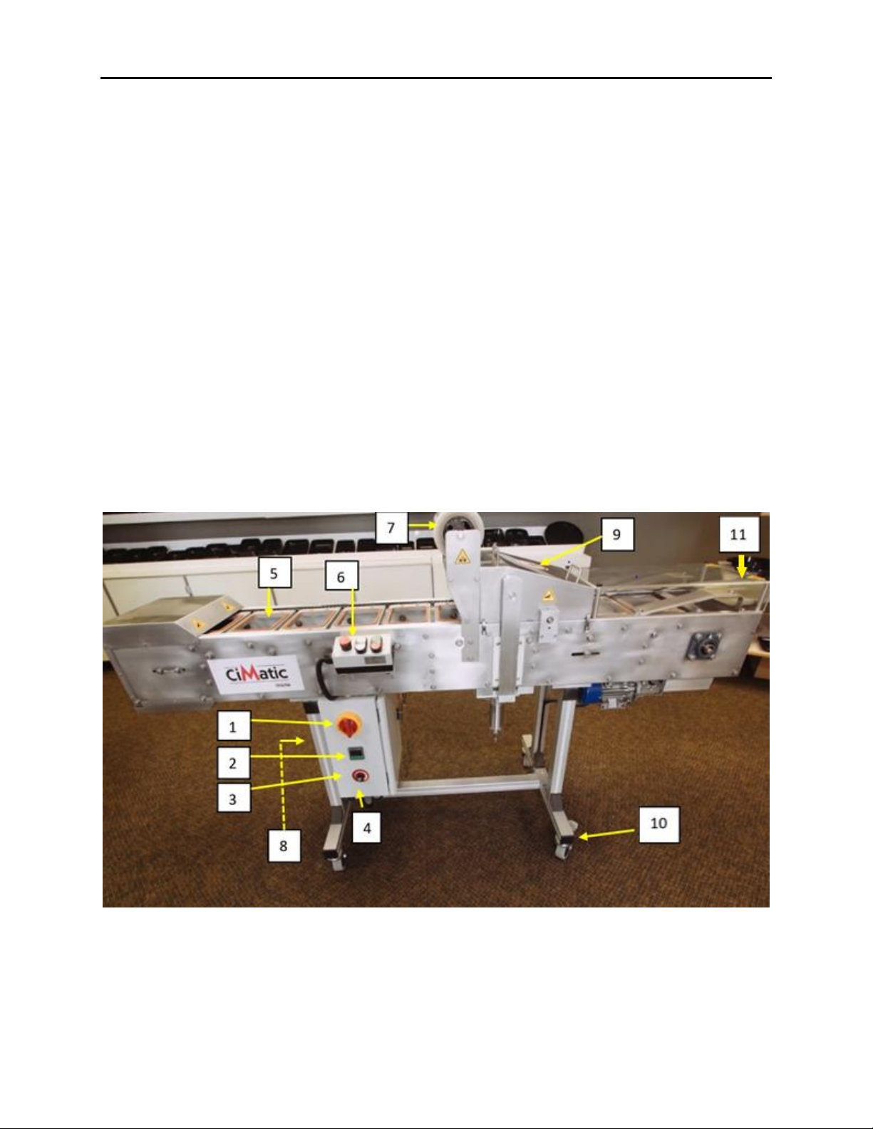
Legend Figure 2
1 Main switch
2 Temperature controller for rotary sealer
3 Speed controller for conveyor
4 Control panel
5 Tray pallets
6 Operator panel (See insert)
7 Unwind film area
8 Air Connection
9 Cover - Rotary Sealer and cutter
10 Locking casters
11 Exit plate: If the plate was placed on the top of the machine for transport, please mount it to the end
of the machine where the trays exit.
Figure 2

DOC. N. CIMATICII
REV. 7
ED. 08.2021
Chapter 2. DESCRIPTION AND TECHNICAL DATA
Legend Figure 3
11 Emergency STOP
12 Direction –Forward/Backwards
13 Run/Stop
Figure 3
Operation cycle (Figure 1 and 2)
The filled trays are placed into the pallets, the run button is pushed and then the conveyor will introduce
the trays into the rotary sealer, through the cutter as well as unload them through the opening at the
exit of the machine.
2.2 Technical data
- Voltage and frequency: 110-120V / 60 Hz
- Installed power: 820 watt
- Input: 7-9 Amps (with optional air compressor)
- Air consumption: 2 CFM at 45 PSI
- Maximum production: 30-35 pieces (2171 Series)
- Size of the trays to be sealed: minimum 2171 Series, maximum 2227 Series
- Maximum reel width: 9.5” (245 mm)
- Size of the machine: 82” x 24” x 48” (2,082 x 610 x 1,220 mm)

DOC. N. CIMATICII
REV. 7
ED. 08.2021
Chapter 3. SAFETY RULES
3.1 General precautions
Before acting on the machine to adjust, service and repair it:
- put the machine into a safe condition by pressing the “emergency” button located
on the operator panel Figure 2;
- power off the machine by turning the main switch to “0” Figure 1;
- remove the electrical plug.
Only the personnel who have been properly trained and informed may service this equipment.
- The removal of cases, doors or walls in unsafe conditions may cause the operator
maintenance person to come into contact with moving members, hot
parts and live devices.
- If safety devices are either removed or tampered with by the user, this will relieve
the supplier of any civil and criminal liability.
- The same conditions will apply if any protection which may be fastened by the screws
is removed without having stopped the machine in advance.
3.2 Specific precautions
The CiMatic II is built with several OPERATOR SAFETY COVERS AND DOORS. NEVER OPERATE THE
CIMATIC II WITH COVERS REMOVED OR DOOR(S) LEFT OPEN!!!
The rotary sealing head can reach a high temperature and should be considered as dangerous. Never
touch the rotary sealing head when hot. Pay great attention when you are working in the proximity of
the rotary sealing head since there is the potential risk of accidentally coming into contact with very hot
parts (200°C !!!).
- It is recommended to use protective gloves.
There is a film cutting blade present. Operating the equipment with the protective cover removed can
result in a potential risk of serious consequence. NEVER OPERATE THE CIMATIC II WITH COVER
REMOVED!!!

DOC. N. CIMATICII
REV. 7
ED. 08.2021
Chapter 4. INSTALLATION
4.1 Transportation and handling
Weight of the machine: Approximately 200 lbs..
To lift the machine, use a lift truck having an adequate capacity (make sure the machine is properly
balanced and pay attention to the screws/bolts protruding from the lower part of the body). As an
alternative provide for slinging and use a hoist complete with ropes which are properly dimensioned and
equipped with hooks at their end.
Tension the ropes slowly. Make sure they will cause no damage. Lift the machine with the greatest care.
When placing it, make sure it is levelled on the floor and installed in a dry room free of any inflammable
material, gas or explosive.
The machine is supplied with locking casters. Never use the CiMatic II without first locking the wheels.
To do so may cause damage.
Careful consideration should be given to the machine installation site. The area you choose should have
solid footing and have proper lighting. Position the machine so that it is accessible from all sides for proper
operation, service and maintenance.
Permitted conditions in the rooms where the machine is placed:
- temperature from: +36°F (+2°C) to +85°F (+30°C)
- humidity from 30% to 90% without any condensate.
4.2 Final inspection before Start Up
Transportation of equipment may result in machine parts coming loose or out of alignment. It is always
advisable to do a visual inspection and check tightness of the screws, nuts, bolts on the system. There is
a toolbox provided with this system in order to facilitate this check.
If, at any time during the start-up or in production, you hear an unusual noise it is advisable that the
system be immediately stopped and the source of the noise be investigated. Not doing so may result in
the warranty being voided.
4.3 Connections
Electric energy
Before plugging in the CiMatic II, make sure the main voltage will correspond to the voltage specified by
the label on the machine and that grounding will comply with the safety rules in force. In case of doubt
about the main voltage, contact the local electric energy supplier.
Compressed air
Connect the compressed air connection (Item 8 - Fig. 2) located in the left side of the control panel. Use
an air hose having a minimum diameter of 1/4” with the proper quick connection fitting.
Chapter 5. OPERATING INSTRUCTIONS
5.1 Locking Caster

DOC. N. CIMATICII
REV. 7
ED. 08.2021
Once you have located the CiMatic II in its operating location lock the casters before operating (10 - Fig.
2)
5.2 Power the equipment on
The power switch (1 -Fig.2) turns the power ON or OFF to the tray sealer. When the switch is in the “ON”
position, all functions of the machine are operational.
5.3 Temperature Controller
The temperature of the sealing drum is controlled by the temperature controller (2-Fig. 2). There is a
thermocouple internally mounted that accurately maintains the temperature of the seal drum. To
change the temperature setting:
1) Press
2) Press the or button to the desired temperature (factory preset is 160 degrees C).
3) Press to register the temperature value.
At start-up, seal drum will reach the correct operating temperature in about 20-30 minutes.
The CiMatic II will not operate if the temperature is below the low preset temperature.
5.4 Drive System
The Directional buttons (Fig.3) “ indicates the direction of the conveyor. When the
directional button is pushed backwards “ “ the conveyor will move backwards. However, the
conveyor will stop the moment the button is released.
When the directional button is pushed forward “ “ the conveyor will start at the predetermined
speed. The speed is set through the potentiometer.
5.5 Speed Controller
The conveyor speed is adjusted through the speed controller (3 -Fig.2). Clockwise increases the speed
while counter clockwise decreases speed. Remember, that if you increase the speed you may need to
increase the temperature to compensate for the time that the tray remains under the sealing head.
DOC. N. CIMATICII
REV. 7
ED. 08.2021
Chapter 5. OPERATING INSTRUCTIONS
5.6 Master Roll
To install a new roll please follow these instructions:
1) Lift unwind roll, with black plastic roll caps, from the chucks
2) Unscrew the collar from one side
3) Remove the black plastic roll caps and insert them in the new roll. Checking to make sure that
the film is unwinding in the correct direction. The inside of the roll is normally the sealing side.
4) Lower the unwind roll back into the chuck
If you have done the above correctly the film should line up correctly with the trays. If not, loosen the
collars and recenter the film.
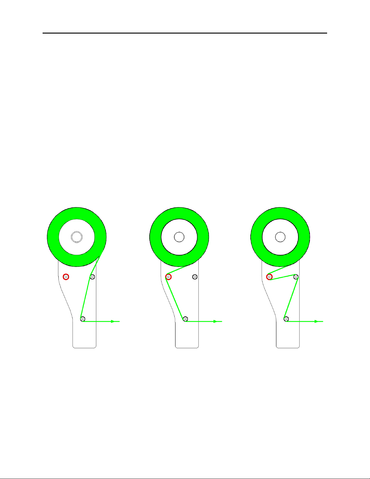
5.7 Film loading
The film should be threaded as shown in Figure 4 below:
Figure 4.
Minimum tension Normal tension Maximum tension

DOC. N. CIMATICII
REV. 7
ED. 08.2021
●You can also adjust the tension by tightening or loosening the two plastic thumbscrews
Located on top of each roll holder.
DOC. N. CIMATICII
REV. 7
ED. 08.2021
Chapter 6. USE OF THE MACHINE
6.1 Start up
These are the procedures to follow in order to put the CiMatic II into operation:
a. Turn “ON” main power switch (1- Fig.2).
b. Ensure that the air supply is turned on and connected (8- Fig.2)
c. Check that the seal drum temperature is properly set (2- Fig.2)
d. Allow seal drum to reach operating temperature. CiMatic will not run if temperature is not
equal to pre-set temperature
e. Thread film into machine (Fig.4). Pass the film between the film idler roll and into the cavity
of the tray holder pallet.
f. Jog conveyor forward (12-Fig.3) until the film is “roughly” located under the sealing head.
g. Load trays into the pallets (5- Fig.2)
h. Push the start button (13- Fig.3)
i. After a few trays the film will run without wrinkles.
j. Continue feeding trays into the pallets
6.2 Shut Down
The following procedure should be followed when turning off the CiMatic II:
a. Stop placing trays into tray holders.
b. Let machine cycle until the last tray is ejected onto the discharge rails.
c. Press stop button (13-Fig.3)
d. Turn main power switch to “OFF” (1- Fig.2).
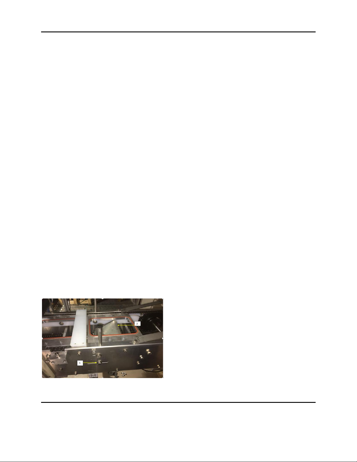
6.3 Tray Discharge
The exit ramp can be adjusted to smoothly lift the trays out of the pallet and transferred to the upper
ramps. Changing from one tray style to another may necessitate the exit ramp be modified. The trays
will line up on the upper ramps and must be removed by the operator.
After loosening the bolt (1 - Fig.5) you then can adjust the exit ramp (2 - Fig.5)
Figure 5.
Chapter 6. USE OF THE MACHINE
6.4 Changing Pallet Styles:

DOC. N. CIMATICII
REV. 7
ED. 08.2021
To change the pallet style (This should only be done by a factory trained operator) you need to follow
the steps below:
1) Stop the CiMatic.
2) Remove the cover (9-Fig.2) by unlatching 4 clasps on both sides of the cover.
3) Remove the knife set integrated with the current pallet style.
-Completely loosen the setscrews located on each knife bearing (use 3mm size hex key in
your toolbox) one setscrew per side.
6.4 Changing Pallet Styles:
-Pull knife module straight up as shown below (pull each side at the same time).
CAUTION:
Great care should be taken when handling the knives as
they are extremely sharp.
Handle knives with leather gloves or use similar
protection for the hands.

DOC. N. CIMATICII
REV. 7
ED. 08.2021
4) Remove the pallets as described in Chapter 6.6 which follows.
5) Place the new pallet set as described in Chapter 6.6 which follows.
6) The new knife set is positioned as follows:
-Slowly lower the knife set into guides. It is imperative that the blade lays in the space
between two pallets. Damage to the knife or the pallets can happen if the knife sprocket
tooth does not mesh with the chain.
-You can jog the machine at the lowest speed to make sure the knife doesn’t hit the plates
when it’s rotating forward and backward. Also, make sure the knife bearings have sat well
on the blocks with the locating pin.
-Tighten the set screw on both side of the new knife set bearings. (use 3mm hex socket key)
6.5 Replacing the Knife Blade:
1) Follow all instructions on preparing the CiMatic II for service which can be found in Section 3.1
General Precautions above
2) The knife has to be removed first as follows:
CAUTION:
Great care should be taken when handling the knives as
they are extremely sharp.
Handle knives with leather gloves or use similar
protection for the hands.
DOC. N. CIMATICII
REV. 7
ED. 08.2021
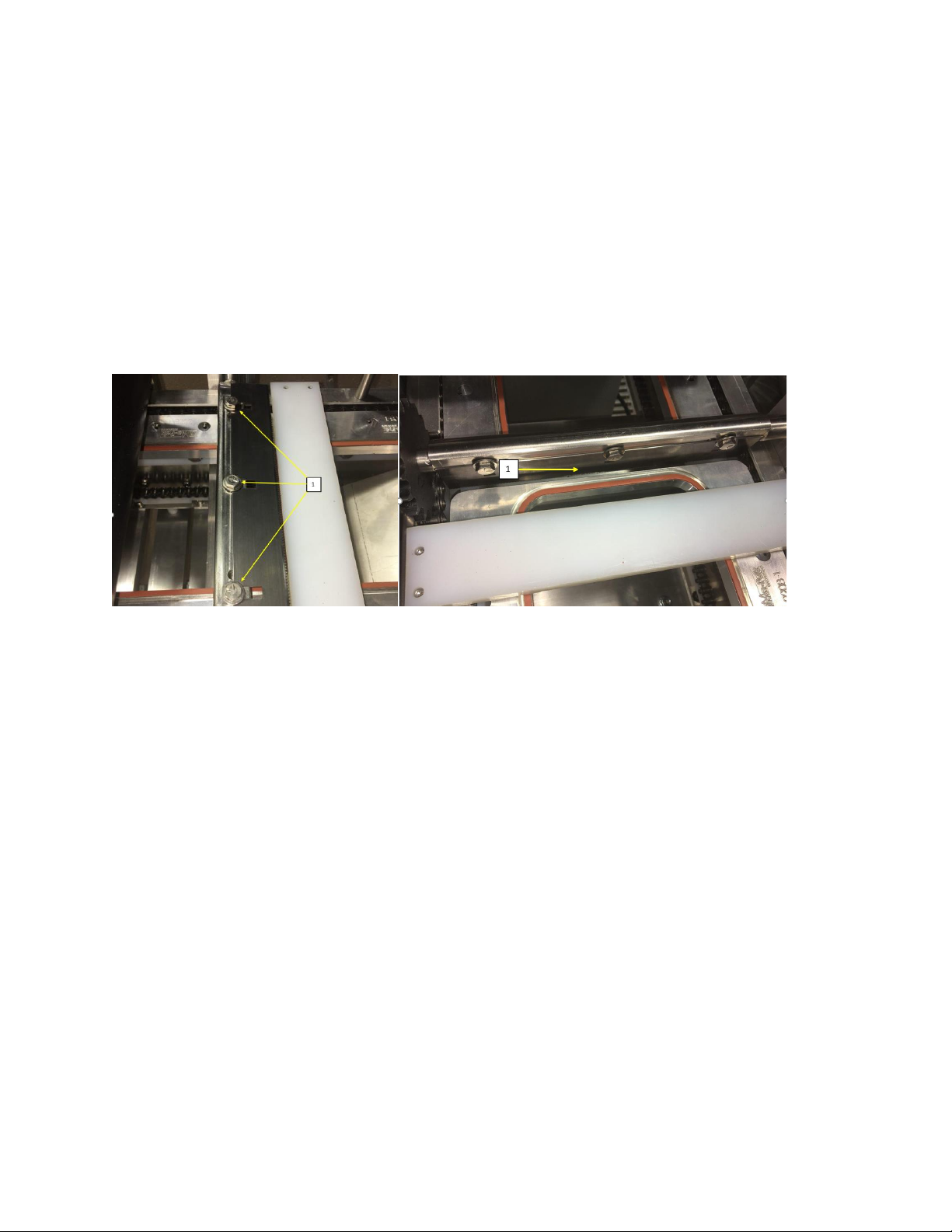
a. Remove the cover (9-Fig.2) by unlatching 4 clasps on both sides of the cover.
b. Jog the pallets and stop when the knife blade is horizontally permitting you to easily
loosen the 3 bolts (7/16ths) (1-Fig 6) holding the knife. The bolts do not need to be
unscrewed completely.
c. Replace the knife with the new one, make sure to put the new knife the same direction
and distance as the old one was.
d. Tighten the bolts.
e. Now jog (12-Fig.3) the CiMatic II to make sure that the blade fits properly between the
pallets (1-Fig 7)
f. Replace cover
Figure 6 Figure 7
DOC. N. CIMATICII
REV. 7
ED. 08.2021
Chapter 6. USE OF THE MACHINE
6.6 Removing the Pallets:
From time to time it may become necessary to remove the pallets. Normally this is not a requirement
unless silicone needs to be replaced.
It is imperative that the pallets be returned to the exact position it was removed from otherwise,
damage to the knife or the pallets can happen.
The pallet can be removed as follows:
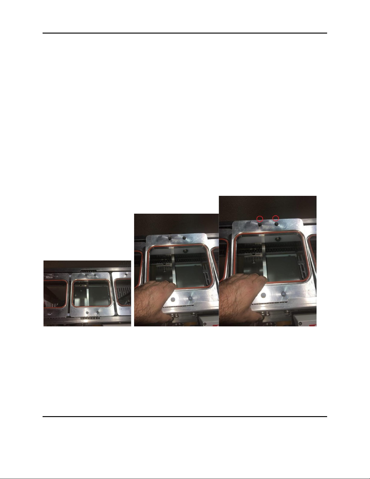
a. Jog (12 - Fig.3) to the pallet unloading sector (Figure 8)
b. Lift pallet and pull it towards the front of the CiMatic II (Figure 9) so that the two pins (Figure
10) at the rear of the pallet clear the chain. You may have to push the rear chain a little with
your thumb
c. Angle the pallet up from the rear and then remove from the front chain
d. Replacement is the opposite of the above remembering that the space between the front and
back pallets has to be the same.
e. The last check is to make sure that the chain is sitting properly on the white plastic guides (front
and back)
Figure 8 Figure 9 Figure 10
6.7 Pressure Setting Rotary Sealing Head
Pressure can be applied to the Rotary Sealing Head by increasing the value on the air regulator which is
located on the left side of the control panel (8 - Fig.2).
However, increase the pressure carefully as the Rotary Sealing head is a Teflon coated part and can be
damaged if there is too much pressure. Maximum pressure should be no more than 45 PSI.
Chapter 6. USE OF THE MACHINE
6.8 Troubleshooting and Possible Remedies

DOC. N. CIMATICII
REV. 7
ED. 08.2021
Problem
Symptom
Check
Machine Does Not Turn
on
When the Power Switch is
Turned ON the temperature
controller does not initialize.
●Machine is not plugged in
●Check that the Emergency Button is not
engaged
●Check Fuses
Machine will not Run
When the Run Button is
pushed the CiMatic II does
not run
●Check step above
●The temperature has not been reached
●There is no compressed air present
●Speed dial is set too low
●Drive chain is broken or off of the drive
sprocket
●Chain is jammed
●The Rotary Heat Seal drum is jammed
down
●Motor drive shows an error (OLF)
Film does not seal to
tray
Film is installed backwards
●Remove and reverse film roll
Pressure is not set high
enough
●Increase pressure at the regulator
Speed is too high
●Turn down the speed
Drum does not get hot
●Temperature controller set too low
●Temperature controller defective
●Temperature relay defective
●Check fuses
●Drum heater defective
●Defective thermocouple
Film Melts or the trays
become distorted
Sealing temperature is too
high
●Check that the temperature is correctly
set.
●Check that the conveyor speed is not set
too low
●Too much film tension
Material Problems
Film does not lie flat on tray
●Too much pressure on Rotary Sealing
Head. Pressure should never exceed 45
PSI
●Rotary Sealing Head not being allowed to
lower properly. Check and clean out
possible debris
●Silicone damaged on pallets
●Product in trays extends above
tray sealing flange

DOC. N. CIMATICII
REV. 7
ED. 08.2021
Chapter 6. USE OF THE MACHINE
6.8 Troubleshooting and Possible Remedies
●Dirty seal drum surface, clean as
described in Maintenance section
●Film is wrinkled on film roll
●film tension correctly set
Poor quality seals
●Film and tray material not
compatible. The CiMatic II has been
engineered to use the CiMa-Pak Trays in
conjunction with the CiMa-Pak film.
●Reduce machine speed
Table of contents


