Nordson 3100V Series Reference guide

OWNER'S RECORD
MODEL AND SERIAL NUMBER INFORMATION:
The model and serial numbers are located at the hose/gun side of the unit.
A duplicate label is provided to you in the space below.
Refer to these numbers whenever you call upon your Nordson Customer Service
Representative regarding this product.
TANK AND HEATING PADS WARRANTY INFORMATION:
With respect to hot melt tanks and bulk melter heating pads with cast-in heating
elements, Nordson agrees to repair or, at it's option, replace any hot melt tank or bulk
melter heating pads determined by Nordson to have defective cast-in heaters, provided
the defect is reported in writing to Nordson within sixty(60) months of the date of
manufacture stamped on the hot melt tank or bulk meter heating pads.
THIS UNDERTAKING IS IN LIEU OF ALL OTHER WARRANTIES, EXPRESS OR IMPLIED,
INCLUDING IVERCHANTABILIry AND FITNESS FOR PARTICULAR PURPOSE.
UNIT INSPECTION INFORMATION:
Factory tested and approved: Date ?-/S-o //
Pump seriar number: 5,4Ct 6 /6q/a
NOTE:
Retain for your this document into owner's manual provided with unit.
l^lose +' 6Lt/J records. lnsert
(zz*vqs) /z+*v65
(z+++G s)
8Fr- TAolcaogSt +AD3tT
55 + AD3'1.
3400v -zEAV4D/R
230883A S401H00513
W
MilNHifN re
IIINE
Ultl t---t6]
ru Fso/oo ffi
IIIiEE
Erd t-rrc I
E
W
w
Nordson
@ gFr- TAotc oeq
Nordson Corporation
307130

.t
SERIES 34OO Y
Hot Melt Material Applicator
with 6:1 SP30 Piston Pump and Vista'Controller
r 3400V-4GAVDUX
Customer Product Manual- Part 331 1g2F
NORDSON CORPORATION o AMHERST, OH|O o USA zl-"'
--'/'{
l
\',;
, -'ttr;:' /
,
f,-\.-".* \
,... tl :. (
Nordson.
$\

(€
,\r
Nordson Corporation welcomes requesls for information, comments and inquiries about its products. General
information about Nordson can be found on lhe lnternet using the following address: http://wwwnordson.com.
Address all correspondence to:
Nordson Corporation
Attn: Customer Service
1'1475 Lakefield Drive
Duluth, GA 30097
Notice
This is a Nordson Corporation publication which is protected by copyright. Original copyright date 1999. No part of
this document may be photocopied, repioduced, or translated to another language without the prior written consent
of Nordson Corporation. The information contained in this publication is subject to change without notice.
Trademarks
AquaGuard, Blue Box, Control Coat, Equi=Bead, FoamMelt, FoamMix, Helix, Hot Shot, Hot Stitch, Meltex,
MicroSet, MultiScan, Nordson, the Nordson logo, OmniScan, Package of Values, Porous Coat, PosFStop, ProLink,
PRX, RBX, Shur-Lock, UniScan, UpTime, and Versa-Spray are registered trademarks of Nordson Corporation.
BetterBook, CF, Controlled Fiberization, Eclipse, Saturn, Seal Sentry, Swirl Coat, and Vista
are trademarks of Nordson Corporation.
Big Orange is a registered trademark of ZEP Manufacturing Company.
Loctite is a registered trademark of Loctite Corporation.
Never Seez is a registered trademark of Bostik CorpoAtion.
Parker Lubricant is a registered trademark of Parker Seal.
Teflon and Viton are registered trademarks of E.l. DuPont de Nemours & Co.
\ =t=-
41."
.:*l---.. *O 2000 Nordson Corporation
All rights reserved
ii
01 EN-01-[3V-3311 92]-1 lssued j
-6-
,v
.a-l}

Nordson CorPoration
OPERATOR'S CARD
P/N 229 777c
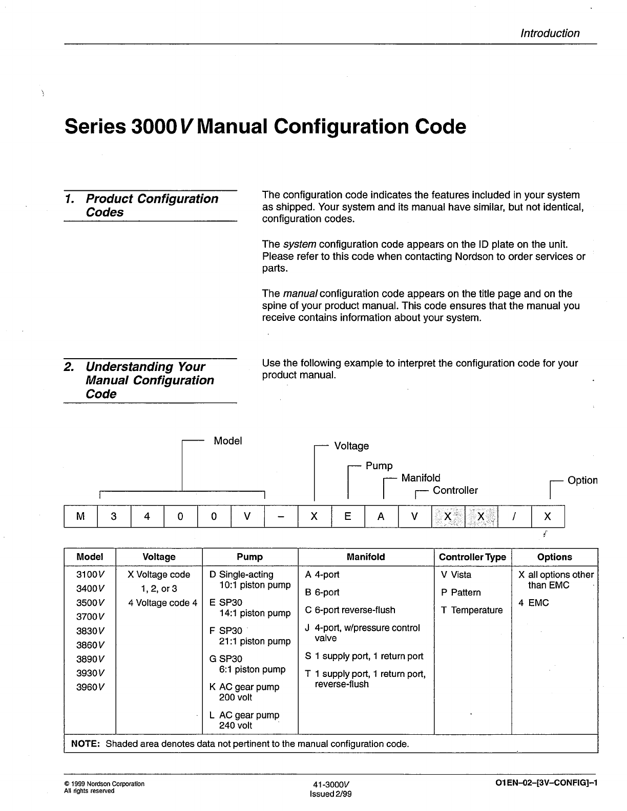
Series 31OO Vlg4OOYl3500 Vl3700V
Hot tMelt tVlaterial APPlicator
with Piston Pump, standard Filter, standard control
IMPORTANT
Give this coPY
to the oPerator
Please Note
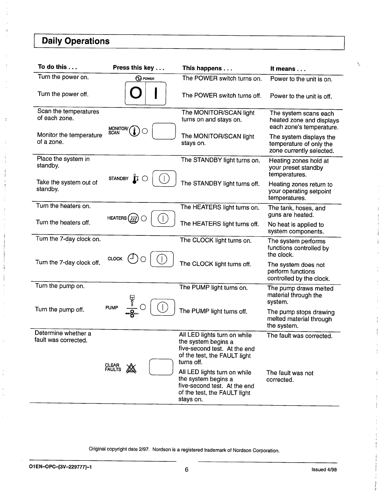
The operator's card contains only information
necessary for daily operation and maintenance'
Foiotreiintormation, reler to the product manual
A copy of this operator's card and an order form for
anotirer operator's card are included in the
introduction part of the operating manual'
AWARNING: Allow only qualified personnelto
perform the following tasks. Observe and
iollow the safety instructions in this document
and all other related documentation'
Always follow the instructions given in the
operator's card and operating manual'
Always follow instructions in the material supplier's
tvtateiiat Safety Data Sheet (MSDS) or material
information sheet.
Even at recommended operating temperatures'
hot melt material may release vapors' Exceeding
prescribed processing temperatures for long
periods of time can result in dangerous
decomposition by-products. Flemove vapors
by drawing them off with an exhaust system'
a
a
a
Safety SYmbols
The following symbols warn against dangers or
oossible sou-rces of danger. Become familiar with
inemt faiture to heed a warning symbol can lead to
personal injury and/or damage to the unit or other
equipment.
A
A
WARNING: Failure to observe can result in
equipment damage, personal injury, or death'
WARNING: Risk of electrical shock' Failure to
obserue can result in personal injury or death'
WARNING: Disconnect equipment from line
voltirge. Failure to observe can result in
personal injury or death.
WARNING: Hot! Risk of burns. Wear
heat-protective clothi n g, saf ety gog gles, and/or
heat-protective gloves depending on the
symbol or symbols shown. Failure to observe
can result in personal injury or death'
WARNING: Pressurized system or material
Release pressure. Failure to observe can
result in serious burns.
@
@
@
A
1
lssued 4/98 o 1 E N-O P C-[3V -229774-1

rvi
Ove EW of Stem Com o
ys nts
ne
p
1Applicator
1. Pump
2. Tank
3. Air regulator
4. Filter and drain valve
5. Controls
Additional System Components
6. Hose
7. Air-operated gun
8. Solenoid valve
2
3
8
4
Clean the exterior sudaces of the applicator and
guns.
2. Check the o-rings and gaskets for leaks.
3. Flush the manifold filter as follows:
a. Reduce the pump air pressure to 0.
c. Open the drain valve over a container by
turning the valve counterclockwise.
56
7
1
b Place containers under all guns and trigger the
guns to relieve hydraulic pressure.
Type A Manifotd
TypeBorSManifold
d. lncrease the pump air pressure until a clean,
steady stream of hot melt materialflows from
the drain valve.
e. Close the drain valve.
f. Return the pump air pressure to the normal
operating setting.
2
Daily Maintenance
ol EN-oPc-[3V -229771_1 lssued 4/98

Dai ly Startu p/Sh utdown
8. When the READY light turns on, press the PUMP
key.
WARNING: When the tank lid is open, hot melt
vapors may be released. Vent the application
area or wear a respirator for protection from
vapors.
Automatic Startup/Shutdown
With the seven-day clock and auto-energize pump
features on, the following occur:
1. The heaters turn on automatically and the pump
starts when the tank reaches either the READY
condition or a temperature you have selected.
2. The heaters turn off automatically and the system
shuts itself down.
ManualStartup
1. Check the adhesive level. lf the level is below
50%, add adhesive to the tank. Fill to within
25 mm (1 inch) of the tank toP.
2. Close the lid immediately to prevent contamination
of the adhesive'
3. lf the POWER switch is off, turn it on.
4. Prepare each gun in your system for operation as
follows:
. Air-operated guns: turn on the operating air.
. Handguns: unlock the trigger.
o Electric guns: turn on the gun driver.
5. Press the HEATERS key. The HEATERS light will
turn on and the unit will begin to heat.
,*'*'@ffis
6. Turn on the pump air pressure and adjust it to the
setting that works best for your system.
7. Check the temperature setting for each heated
zone.
9. Check the adhesive level periodically. Refill the
tank before the level drops below 50%.
ManualShutdown
1. Press the PUN/P key. The PUMP light willturn off
and the pump will stoP.
?L'
A
A
PUMP +
2. Place containers beneath all guns and trigger the
guns to relieve hydraulic pressure.
3. Use one of the following methods to prevent
accidental gun triggering:
. Air-operated guns: reduce air pressure to 0
. Handguns: place the trigger safety in the
locked position.
. Electric guns: turn off the gun driver.
WARNING: Never hang a handgun by its
trigger. The gun can accidentally discharge
material, causing burns.
4. Press the HEATERS key. The HEATERS light will
turn off.
r,*rens6D o
\<=/
3
lssued 4/98 o 1 E N-O PC-[3V -22577n-1

Daily Operations
Todothis... Press this key . . . This happens .It means. .
oI
Turn the power on POWER The POWER switch turns on Power to the unit is on
Turn the power off The POWER switch turns off. Power to the unit is off
Scan the temperatures
of each zone. The MONITOR/SCAN light
turns on and stays on. The system scans each
heated zone and displays
each zone's temperature.
The system displays the
temperature of only the
zone currently selected.
$lf,l'o"o c
Monitor the temperatu re
of a zone. The MONITOR/SCAN light
stays on.
Place the system in
standby. The STANDBY light turns on.
The STANDBY light turns off.
Heating zones hold at
your preset standby
temperatures.
Heating zones return to
your operating setpoint
temperatures.
Take the system out of
standby.
STANDBY $o
Turn the heaters on The HEATERS light turns on.
The HEATERS light turns off.
The tank, hoses, and
guns are heated.
No heat is applied to
system components.
Turn the heaters off. HEATEHS @ o
Turn the 7-day clock on. The CLOCK light turns on. The system performs
functions controlled by
the clock.
The system does not
perform functions
controlled by the clock.
CLOCK
Turn the 7-day clock off. The CLOCK light turns off
Turn the pump on The PUMP light turns on. The pump draws melted
materialthrough the
system.
The pump stops drawing
melted material through
the system.
Turn the pump off PUMP The PUMP light turns off
F
I
"Fo
Determine whether a
fault was corrected. All LED lights turn on white
the system begins a
five-second test. At the end
of the test, the FAULT light
turns off.
All LED lights turn on while
the system begins a
five-second test. At the end
of the test, the FAULT light
stays on.
The fault was corrected.
The fault was not
corrected.
PlEti. A
original copyright dale 2/92. Nordson is a registered trademark of Nordson corporation.
6
o 1 E N-O PC-[3V -2297771-1 lssued 4/98

Vista Contro! Panel
13
12
11
1. Zone indicator lights
2. STANDBY or SETPOINT temperature light
3. SYSTEM SETTINGS light
4. Up key for system settings
5. Down key for system settings
6. Move right key
7. Clock INTEFIVAL lights
10 I
8. POWER switch
9. Clock feature lights
10. Control keys
11. Control lights
12. Up key for selector display
13. Up key for multipurpose display
14. Selector display
8
19
15. Multipurpose display
16. FAULT light
17. READY light
18. Actual temperature display
19. Down key for multipurpose
display
20. Enter key
15 16 17
20
2
3
4
5
b
7
8
4
Vista* FAULT J
AREADY
I
t
I50F )5tF
J
Of *,-*
Olo^-rt EEfE
D{IEMI HE Ot'}I
IEMPERAIUR€ rl
2a
1-u
SYSIEM
SEINNGS
OQe**.
o!Iffi*
z'r flz un
\-/ l- srmw
O @ *'o"*
O @ *ro"o*
INTERVAL
E
1
'61
\y'2
O qocK
POWER
o
@o
sr "rrr $ O
@o
CLOCK
CLEAR
FAULTS &
PUMP
Qo
3
0
o 1 E N-O PC-[3V -2297 77)-1 lssued 4/98

Record of Vista Control Settings
Temperature Settings
Zone
Type
lnternal
Hose
Gun
Zone
Type
Hose
Gun
Clock Settings
Zone 1 Temperatures Zone2 Temperatures Zone 3 Temperatures
Zone 6 Temperatures
Band
Band
Operating Standby
Operating Standby Band
Zone 5 Temperatures
Zone 4 Temperatures Operating Standby
Operating Standby Band
Heater lntervals Monday Tuesday Wednesday Thursday Friday Saturday Sunday
Heaters On-1
Heaters Off-1
Heaters On-2
Heaters Off-2
Standby lntervals
Standby On-1
Standby Off-1
Standby On-2
Standby Off-2
System Settings
System ready time delay:
Overtemperature setpoint
Pump air pressure:
Global temperature band:
Auto-energize pump
temperature setting:
Startup: tr Sequential / tr Simultaneous
Auto-energize heaters: tr On / ! Off
Auto-energize pump: tr On / tr Off
Warning or power output: tr Warning / E Power on
Ready or pump output: tr Ready / E Pump on
Password: trOn/trOff
5
lssued 4/98 o 1 E N-O PC-[3V -2297771-1

lntroduction
Series 3000 V Manual Configuration Code
1. Product Configuration
Codes
2. Understanding Your
Manual Configuration
Code
The configuration code indicates the features included in your system
as shipped. Your system and its manual have similar, but not identical,
configuration codes.
The system configuration code appears on the lD plate on the unit.
Please refer to this code when contacting Nordson to order services or
parts.
The manualconfiguration code appears on the title page and on the
spine of your product manual. This code ensures that the manual you
receive contains information about your system.
Use the following example to interpret the configuration code for your
product manual.
- Voltage
Pump
Model
Manifold
f Controller IOption
M3400V X EAV:. f,.1:: Ix
Model Voltage Pump Manifold ControllerType Options
31 00y
3400v
3500v
3700v
3830v
3860v
3890v
3930v
3960v
X Voltage code
1,2, or 3
4 Voltage code 4
D Single-acting
10:1 piston pump
E SP3O
14:1 piston pump
F SP3O
21:1 piston pump
G SP3O
6:1 piston pump
K AC gear pump
200 volt
L AC gear pump
240 volt
A 4-port
B 6-port
C 6-port reverse-flush
J 4-port, w/pressure control
valve
S 1 supply port, 1 return port
T 1 supply port, 1 return port,
reverse-flush
V Vista
P Pattern
T Temperature
X alloptions other
than EMC
4 EMC
NOTE: Shaded area denotes data not pertinent to the manual configuration code.
@ '1999 Nordson Corporallon
All riqhts reserued 41-3000y
lssued 2/99 ol EN-02-[3V-CONFlG]-1

lntroduction
ol EN-02-[3V-CONFTG]-I 41-3000v
lssued 2/99 @ 1 999 Nordson Corporation
All rights reserved

lntroduction
Congratulations on the Purchase of
Your Nordson Product
Your Safety is lmportant to
Nordson
It's Easy to Use This Product
Manual
We Welcome Your
Suggestions
Nordson equipment is engineered and manufactured in accordance with
strict specifications, using high-quality components and state-of-the-aft
technologies that assure reliable, long-term performance. Your product
was thoroughly tested for proper operation prior to shipment.
Before unpacking and installing your new equipment, please read this
manual. lt is your guide to safe installation, productive operation and
effective maintenance. We recommend that you keep the manual
available for future reference.
Carefully read the safety instructions in the Safefy section. Your product
is designed for safe operation when used according to the published
instructions. However, potential hazards exist when operating
instructions are not followed.
This introductory section provides general information including
recommended spare parts and how the parts can be ordered.
Part A includes safety instructions as well as descriptions of product
installation, operation, maintenance and general troubleshooting
procedures.
Part B contains detailed information concerning the product and its
subassemblies.
Parts C, D and E provide information covering hot melt hoses, guns and
accessories.
The glossary and index at the end of the manual explain technical terms
and assist in locating specific information.
Data and specifications included in this manual are accurate at the time
of publication. Nordson reserues the right to change the contents of this
manual and/or specification without notice.
Nordson is committed to providing product manuals that meet the needs
of its valued customers. We invite you to use the Comments and
Corrections page included in this section to offer suggestions for
continued improvement of this manual.
@ 1994 Nordson Corporation
All rights reseNed lssued 9/94 olEN-o3-[XX-CONG]-1

lntroduction
olEN{3-txx-coNcl-1 lssued 9/94 @ 1994 Nordson Corporation
All rights reserved

Table of Contents
Manual
Table of Contents
Becommended Spare Parts
and Supplies
General Hot Melt Material
P rocessi n g I nstructi ons
Operator's Card
Section A 1
Safety
Section A 2
Description
1. Operate Safely
2. Safety Symbols
3. Qualified Personnel
4. lntended Use
5. lnstallation and Electrical Connections ...
6. Operation ..
Less-Obvious Dangers
Action in the Event of Unit Malfunction
Danger of Burns
Maintenance/Repair
Cleaning
Thermoplastic Hot Melt Material .
Equipment and Material Disposal
7.
8.
9.
10
A 1-1
A1-2
A 1-3
A 1-3
A 1-4
A 1-4
A 1-5
A 1-5
A 1-6
A 1-6
A 1-7
A 1-8
A 1-B
A2-1
A2-1
A2-2
A2-3
A2-3
A2-3
1. lntended Use . .
2. Overview
3. FunctionalDescription
Startup Mode . .
Operating Mode
Standby Mode .
@ 2000 Nordson Corporatlon
All rights reserved 41-3000v
lssued 5/O0 Ol EN{'I-[3V-TOC7-127

ii Table of Contents
Section A 2
Description @ontd)
4. tilajor Components . . . .
Tank .
A2-5
A 2-6
A2-7
A2-8
Pump
Ivlanifold
Manifold Block and Hose Connectors
Manifold Filter .
Drain Valve
Pressure Relief Valve
Air Pressure Regulator
Operator Panel .
.. A2-8
.. A2-8
5. ControlSystem
Features of the Operator Panel . . .
System Status Area
FAULT Light .
READY Light .
Displays Area .
Selector Display and Up Key . . . .
Multipurpose Display and Keys . .
Actual Temperature Display .....
Enter Key
System Setup Area .
Move Up and Move Down Keys
Move Right Key . .
TEMPERATURE ATea
SYSTEM SETTINGS Area ......
CLOCK Area
System Controls Area .
MONITOR/SCAN Key and Light . .
STANDBY Key and Light .
HEAf,ERS Key and Light
CLOCK Key and Light
PUMP Key and Light
CLEAR FAULTS Key....
POWER Switch
Specifications . .. .
Dimensions
Explanation of Configuration Code
Code Descriptions
Example
. A2-9
. A2-9
. A2-9
. A2-9
A2-10
A 2-10
A2-11
A2-11
A2-11
A2-12
A2-12
A2-13
A2-13
A2-13
A2-14
A2-14
A2-14
. A2-1s
. A2-15
6.
7.
8.
A2-15
A2-16
A 2-16
A2-17
A2-18
A2-18
A 2-18
A2-18
42.'IB
A 2-19
A2-20
A2-21
A2-22
A2-24
01 E N-O/I-[3V-TO C)-1 27 41-3000v
lssued 5/00 o 2000 Nordson Corporatlon
All rights reserved

Table of Contents iii
Section A 3
lnstallation 1. lntroduction
2. Unpacking
3. lnspection
.... A3-1
.. A 3-1
.. A 3-1
A 3-1.
A3-2
A 3-3
A 3-3
A 3-4
A3-4
A 3-6
A3-7
4.
5.
lnstallation Requirements . . .
Location Requirements .. ... . . . .
Wiring Requirements ....
Hose/Gun Power Requirements
Mechanical I nstallation
Mounting the Unit
lnstalling the Tank Strainer
Connecting the Air Supply
lnstalling Guns .
To lnstallan Air-Operated Gun
To lnstall an Electric Gun .
To lnstalla Hand-Operated Gun
lnstalling Hoses
Electrical I nstallation
Connecting Gun and Hose Cordsets . .
Opening the Electrical Enclosure
Connecting a Triggering Device for the pump Solenoid
Valve .
Connecting Output Contacts (Optional)
Connecting Electrical Seruice
Closing the Electrical Enclosure
System Programming Procedures .. ..
Programming System Controls
Programming Optional Features
Programming SYSTEM SETTTNGS Controls
ProgrammingTEMPEHATURE Controls . . ..
]o .f 1qOrq.m Setpoi nt and Stan dby Temperatu res
lndividually
To Program All Zones to the Same Temperature
Programming CLOCK Controls
To Set the Clock
To Set Standby and Heater Tmes
To Change a Standby or Heater Time .
To Delete a Standby or Heater Time .
To Delete Times for an Entire Day .
An Example of How to Use the Seven-Day
ClockFeature....
6.
7.
. A3-8
. A3-8
. A3-9
. A3-9
A 3-'t0
A 3-14
A 3-14
A 3-16
A3-1,7
A 3-19.
A3-22
A 3-25,
A 3-26
A3-27
A 3-29r
A 3-29,
A 3-33
A 3-36
A 3-38
A 3-39
. A 3-40
. A 3-43
. A 3-45
. A 3-46
. A 3-46
. A3-47
@ 2000 Nordson Corporatlon
All dghts reserved 41-3000v
lssued 5/00 ol EN{4-[3V-TOC]-127

iv Table of Contents
Section A 3
lnstallation @ontd)
B.
9.
System Preparation
Filling the Tank with Adhesive
Flushing the System
Adjusting the Circulation ControlValve .
Records of System Settings
Record of SETPOI NT (Operatin g) Temperatu re Settings
Record of Standby Temperature Settings
Record of Set Times for Heaters On and Heaters Off
Record of Set Times for Entering and Exiting Standby
Record of Customized System Settings Features
Record of Air Pressure Settings
Record of System Faults
Record of System Warnings . . .
1. lntroduction
,
2. OperatingProcedures
Turning the Seven-Day Clock On and Off . . . . . .
Automatically Starting the Unit
Manually Starting the Unit
Checking the Adhesive Level and Filling the Tank
Placing the Unit ln Standby Mode .
Taking the Unit Out of Standby Mode . . . .
Automatically Shutting Down the Unit . . . .
Manually Shutting Down the Unit . .
3. System Monitoring Procedures
Checking the ZoneTemperatures .... ...
Checking the Programmed SYSTEM SETTINGS
Features
Checking the Warning or Fault Log . .
Running a System Test .
4. Operating Procedures for Optional Features
5. Procedure for Changing Adhesives
A3-47
A3-47
A 3-48
A 3-51
A 3-52
A 3-52
A 3-53
A 3-54
A 3-55
A 3-56
A 3-57
A 3-58
A 3-59
Section A 4
Operation
.. A4-5
A4-1
A4-1
A4-2
A4-2
A 4-3
A4-4
A 4-5
A 4-6
A 4-6
.. A4-6
.. A4-7
.. A4-7
.. A4-8
. A4-10
. A4-10
. A4-11
01 E N-o't-[3V-TO Cl-1 27 41 -3000v
lssued 5/00 @ 2000 Nordson Corporatlon
All rights reserved

Table of Contents v
Section A 5
Maintenance 1. lntroduction
2. MaintenanceSchedule
Checking Run Time of Heaters
3. Maintenance Procedures .. . .
Relieving System Pressure
Replacing Hose Connector or Plug O-Rings
To Remove Hose Connector or Plug O-Rings
To lnstall Hose Connector or Plug O-Rings .
Flushing a Standard Manifold Filter.
Cleaning a Standard Manifold Filter .
Flushing the System
To Prepare for Flushing the System
To Flush the System with Hot Melt Material
To Flush the System with a Flushing Material
To Flush the System with Type R Fluid . . . . .
To Restore the Unit to Normal Operation . . . .
lntroduction
Overview of the Hydraulic System . .
Troubleshooting .
Troubleshooting Table
Troubleshooting Procedures ... .
Manifold Blockage Check ... .
Pump Siphon Ball Seat Check
Actuator Check
Pump Solenoid Valve Check .
Pump Air Section Check
4. Pump Repair Procedures ....
Cleaning or Rebuilding the Pump . .. ..
Preparation for Pump Removal . .. ..
Pump Removal
Actuator Removal
Pump Air Section Disassembly . ....
Pump Hydraulic Section Disassembly
Pump Component Cleaning .
Pump Hydraulic Section Assembly .. . ..
Pump Air Section Assembly
Actuator lnstallation
System Restoration
Repositioning or Replacing the Shifter Fork
A 5-1
A5-2
A 5-3
A 5-3
A 5-3
A 5-4
A 5-4
A 5-5
A 5-6
A5-7
A 5-11
A 5-11
A 5-14
A 5-15
A 5-18
A 5-20
Section B 1
Hydraulics 1.
2.
3.
B 1-'l
B 1-2
B 1-3
B 1-3
B 1-5
B 1-5
B 1-6
B 1-7
B 1.8
B 1-9
B 1-10
B 1-11
B 1-11
B 1-11
B 1-12
B 1-13
B 1-16
B 1-20
B 1-21
B 1-22
B 1-23
B 1-23
B 1-24
B 1-25
@ 2000 Nordson Corporatlon
All dghts reserued 41-3000v
lssued 5/00 O 1 E N-O/I-[3V-TO C1-1 27

vi Table of Contents
Section B'l
Hydraulics (contd) 5. Actuator Repair Procedures . . .
Replacing the Actuator . ... .
Actuator Removal
Actuator lnstallation
Cleaning or Replacing the tilagnet Assembly
Magnet Assembly Removal
Magnet Assembly lnstallation
Cleaning or Replacing the Air Valve .
Air Vaive Removal
Air Valve lnstallation
Replacing the Bumper Assembly
6. Pump Solenoid Valve Replacement Procedures
Removing the Solenoid Valve .
lnstalling the Solenoid Valve .
7. Manifold Repair Procedures . . . .
Replacing the Pressure Relief Valve
Replacing the Drain Valve .
Replacing the Manifold
lllustrated Parts Lists
Using the lllustrated Parts List . . . . .
UpTime Pack for Pump G
Piston Pump Parts List . .
Actuator Parts List
Solenoid ValveAssembly Parts Lists . .......
Air Pressure Regulator and Filter Assembly Parts List
Parts Lists for Manifold A
Manifold Assembly Parts List
Filter Assembly Parts List . .
1. lntroduction
2. Overview of the Control System . . . .
ControlAssembly
Unit-Specific Boards
Optional lnpuUOutput Board
Control System on 480 Vac Three-Phase Units
B 1-27
B 1-27
B 1-27
B 1-28
B 1-29
B 1-29
B 1-32
B 1-33
B 1-33
B 1-35
B 1-36
B 1-37
B 1-37
B 1-38
B 1-39
B 1-39
B 1-40
B 1-40
B'.t-41
B 1-41
B 1-42
B 1-45
B 1-48
B 1-50
B 1-52
B 1-53
B 1-54
B 1-56
8.
Section B 2
Control B2-1
B?-2
B2-2
B 2-3
B2-3
B 2-4
O 1 E N-Ort-[3V -T O C1-1 27 41-3000v
lssued 5/00 @ 2000 Nordson Corporation
All rights res€rved

Table of Contents vii
3. TroubleshootingTables
Electrical Safety During Troubleshooting B 2-4
B 2-5
B2-5
B2-6
B2-7
B 2-7
B 2-8
B2-8
B 2-10
B 2-11
B2-12
B2-14
B 2-15
B 2-17
B 2-18
B 2-19
B 2-19
Opening and Closing the Electrical Enclosure
Opening
Closing
lnternal, Hose, or Gun Zone Not Heating . . . .
Settings Changed or Lost
Unit Not Powering On ..
Control System lndicating a Warning
Out-of-BandWarning :.....
Under-Temperature (UT) Warning . . . . . . .
ControlSystem lndicating a Fault
Over-Temperature (OT) Fault
Resistance Temperature Detector (RTD) Fault
Fault-Code Fault (F1 -F7)
4. Troubleshooting Procedures .
Checking the POWER Switch
Checkin Distribution Board Harnesses
and the
Checking a Heater or Heater Circuit
Checking aThermostat ....
Checking an RTD or RTD Circuit . ..
B2-20
B2-22
B2-24
B 2-25
B2-29
B2-29
B2-32
B2-32
B2-32
B 2-33
B2-34
B 2-35
B 2-36
B 2-36
B 2-36
B 2-36
B 2-37
B 2-38
B 2-39
B 2-39
B 2-41
B2-41
B 2-42
B2-42
B 2-44
5. Repair Procedures . . .
ReplacingaFuse..
Replacing a ControlAssembly Board
Preparation for Removal
Power Board Removal
Power Board lnstallation
Control Board Removal
Control Board lnstallation
Display Board Removal .. ..
Display Board lnstallation
System Restoration
Replacing the Operator Panel . . . .
OperatorPanel Removal ......
Operator Panel lnstallation .. ...
Replacing the Control Assembly . .
ControlAssembly Removal . ...
ControlAssembly lnstallation . .
Replacing a Unit-Specific Board ..
Replacing an FITD or a Thermostat
RTD or Thermostat Removal
RTD or Thermostat lnstallation
@ 2000 Nordson Corporation
All rights reserved 4'l-3000v
lssued 5/00 ol EN{4-[3V-TOCI-127
Other manuals for 3100V Series
2
This manual suits for next models
3
Table of contents
Other Nordson Melting Machine manuals

Nordson
Nordson PURBlue 7156681A User manual

Nordson
Nordson 3930 User manual

Nordson
Nordson 2302 User manual

Nordson
Nordson 3100 User manual

Nordson
Nordson 3500 Series Parts list manual

Nordson
Nordson ProBlue Flex User manual

Nordson
Nordson ProBlue P4 Reference guide

Nordson
Nordson ProBlue 1028303 User manual

Nordson
Nordson DuraDrum User manual

Nordson
Nordson AltaBlueA4TP Reference guide