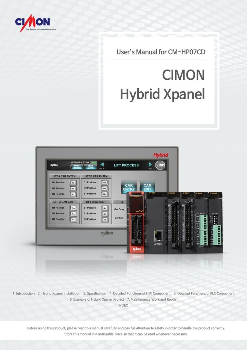
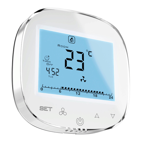
Cimon Xpanel 4 User manual

•
Xpanel 4”, 7”

- 2 -
CONTENTS
Essential Safety Precautions ……………………………… 03
General Safety Precautions ………………………………… 05
Package Contents …………………………………………… 07
Dimensions ………………………………………………… 08
Interfaces …………………………………………………… 09
Installation …………………………………………………… 11
Wiring & Power Supply Cautions ………………………… 13
Grounding Cautions ………………………………………… 14
Specifications ………………………………………………… 15
Project Download …………………………………………… 18
Product Warranty……………………………………………… 26

- 3 -
Precautions for design
• Do not implement a trigger in the software for emergency stop of hazardous operation. If
Xpanel is damaged while output signal remain ON or OFF, fatal accident may be caused.
Design an emergency stop switch outside of the product so it can be manually stopped.
• Do not use Xpanel for the purpose of generating an alarm for injury to operators,
breakdown of devices, or production halt.
• Design the system so that it can be hand-operated in case the product malfunctions.
• Do not use Xpanel as a control unit on applications requiring extreme stability such as
airplane control device, aerospace device, centralized data processing device, nuclear
control system, medical life support system, etc.
• In case Xpanel is used in transportations such as trains, vehicle, vessels, or warning
devices for disasters and crime, various safety devices, and medical devices excluding
life support system, you are required to design backup or failure provision system to
secure reliability and stability.
• Even if the screen is black, the unit could still be turned on with a dead LCD backlight.
When the operator touches a panel in this situation, the action could cause device’s
malfunction. Do not use this product for controlling safety devices such as emergency stop
switches.
Precautions for installation
• Please do not disassemble or modify the Xpanel. It will void the warranty and may cause
an electric shock.
• This version of the Xpanel is not rated for flammable environments. Do not use this Xpanel
around flammable gases. It may cause an explosion.
Essential Safety Precautions
WARNING

- 4 -
Precautions for wiring
• Make sure to check if the device’s power supply is turned off before wiring. Failure to do
so may cause electric shock or damage to the device.
• Do not use power beyond the specified voltage range of the PC. Doing so may cause fire,
electric shock or damage to the device.
Maintenance
• The Xpanel uses a lithium battery to back up the internal clock. Do not replace this battery
by yourself because it may cause an explosion. If the battery needs to be replaced, please
contact your local service center.
Maintenance
• The LCD contains a powerful irritant and if for any reason the panel is damaged and this
liquid contacts any part of your body, be sure to wash that area with running water for 15
minutes. If any of this liquid enters your eye, flush your eye for 15 minutes with running
water and contact a physician.
Essential Safety Precautions
WARNING

- 5 -
Precautions for installation
• Be sure to securely connect all cable connectors to the Xpanel. A loose connection may
cause incorrect input or output.
• Make sure to install the unit vertically.
Precautions for wiring
• Field Ground (FG) wires must be run individually from each unit to the master grounding
terminal. DO NOT daisy chain the FG wires between devices.
• Correctly wire the Xpanel, be sure that the rated voltage and terminal layout are within the
designated range. If the voltage supplied differs from the rated voltage, or incorrect wiring
or grounding is performed, it may cause a fire or unit malfunction and it will void the
warranty.
• Make sure to tighten the screw with standard torque (0.5~0.6Nm). Loose connections may
cause short, fire or malfunction.
• Be careful that metal debris do not enter the Xpanel, they may cause a fire, Xpanel
damage or malfunction.
Precautions for unit disposal
• When this unit is disposed of, it should be done so according to your country’s regulation
for similar types of industrial waste.
CAUTIONS
Essential Safety Precautions

- 6 -
• Do not strike the touch panel with a hard or pointed object, or press on the touch panel
with too much force, since it may damage the touch panel or the display.
• Do not install the Xpanel where the ambient temperature exceeds the allowed range.
Doing so may cause the Xpanel to malfunction or shorten product lifespan.
• Do not restrict or limit naturally occurring rear-face ventilation of the Xpanel, or storing or
using the Xpanel in an environment that is too hot.
• Do not use the Xpanel in areas where large, sudden temperature changes can occur.
These changes can cause condensation to form inside the unit, possibly causing the unit
to malfunction.
• Do not allow water, liquids, metal or charged particles to enter inside the Xpanel, since
they can cause either a Xpanel malfunction or an electrical shock.
• Do not store or use the Xpanel in direct sunlight, or in excessively dusty or dirty
environments.
• Do not store or use the Xpanel where strong jolting or excessive vibration can occur.
• Do not store or use the Xpanel where chemicals (such as organic solvents, etc.) and acids
can evaporate, or where chemicals and acids are present in the air.
• Do not use paint thinner or organic solvents to clean the Xpanel.
• Do not store or operate the LCD display in areas receiving direct sunlight, since the sun's
UV rays may cause the LCD display’s quality to deteriorate.
• After turning the Xpanel OFF, be sure to wait a few seconds before turning it ON again. If
the Xpanel started too soon, it may not start up correctly.
• Due to the possibility of unexpected accidents, you must back up the project data of the
Xpanel regularly.
General Safety Precautions

- 7 -
The following items are contained in the package of the Xpanel. Before using the
Xpanel, please confirm that all items listed here are present.
• Xpanel Unit • Fastener
• Power plug • Installation Guide
This unit has been carefully packed, with special attention to quality.
However, should you find anything damaged or missing, please contact your local
Xpanel distributor immediately.
Package Contents

- 8 -
Unit: mm
Dimension
• XT07
• XT04

- 9 -
1) XT04/XT07 COM Ports
• COM1: RS-232C / COM2: RS-422/485
This interface is used to connect the Xpanel to the host (PLC), via an RS-232C or RS-
422/485 cable. COM1 and COM2 share pins of 9Pin DSUB connector.
Connector Pin No.
Name
Description Port
1
SDA
Send Data A COM2
2
RD
Receive Data
COM1
3
TD
Transmit Data
COM1
4
RDA
Receive Data A
COM2
5
SG
Signal Ground
COM1
COM2
6
SDB
Send Data B COM2
7
RTS
Request To Send
COM1
8
CTS
Clear To Send COM1
9
RDB
Receive Data B
COM2
● Normal communication is not guaranteed when using USB connector as a
communication port in ordinary times.
• In case of RS-485 cable (2-wire) connection, connect only both SDA and
SDB lines.
• The RS-485 of the Xpanel runs under auto toggle mode.
• To reduce the risk of damaging the RS-422 circuit, be sure to connect the
Pin 5(SG) terminal.
Connector Pin No.
Name
1
SDA
2
RD
3
TD
4
RDA
5
SG
6
SDB
7
RTS
8
CTS
9
RDB
Interfaces

- 10 -
2) Ethernet
This interface complies with the IEEE802.3 for Ethernet (10BaseT/100BaseTX)
RJ45 Connector RJ45 Jack
Direct Cable: Host ↔ HUB
Cable No
Color Color No
Cable
1
Orange/W
Orange/W
1
2
Orange
Orange
2
3
Green/W
Green/W
3
4
Blue Blue
4
5
Blue/W
Blue/W
5
6
Green Green
6
7
Brown/W
Brown/W
7
8
Brown Brown
8
Crossover Cable: Host ↔ Host
Cable No
Color Color No
Cable
1
Orange/W
Green/W
1
2
Orange Green
2
3
Green/W
Orange/W
3
4
Blue Blue
4
5
Blue/W
Blue/W
5
6
Green
Orange
6
7
Brown/W
Brown/W
7
8
Brown Brown
8
• Create a Panel Cut and insert the Xpanel into the panel from front.
INSTALLATION
Interfaces

- 11 -
Unit: mm
• XT07
• XT04
Installation

- 12 -
• Attach the Installation Fasteners from inside the panel
• Insert each the hook of fastener into slot and tighten it with a screwdriver
• Tightening the screws with too much force can damage the case of the Xpanel.
• The necessary torque is 0.5kgf.cm.
•
The torque of front USB cover must be less than 1kgf.cm.
• Depending on the thickness of installation panel, the number of installation fasteners
used may need to be increased to provide the desired level of moisture resistance.
Installation

- 13 -
• Make sure to check if the device’s power and external power supply is turned off before
wiring, via a breaker, or similar unit. Failure to do so may cause electric shock or damage
to the device.
• Since there is no power switch on the Xpanel unit, be sure to attach a breaker- type switch
to its power cord.
•
To avoid a short caused by loose ring terminals, be sure to use ring terminals with an insulating
sleeve.
•
When the FG terminal is connected, be sure the wire is grounded. Not grounding the Xpanel unit
will result in excess noise and vibration.
● Connecting the Xpanel Power Cord
When connecting the power cord, be sure to follow the procedures below.
• Confirm that the Power Cord is unplugged from the power supply.
• Unscrew the screws from the middle three (3) terminals, align the Ring Terminals and
re-attach the screws.
• Confirm that the ring terminal wires are connected correctly.
• The torque required to tighten these screws is 0.678_0.813lbf*ft (0.5 ~ 0.6N•m)
Wiring
WARNING

- 14 -
Please pay special attention to the following instructions when connecting the power cord
terminals to the Xpanel unit.
• If the power supply voltage exceeds the GP's specified range, connect a voltage
transformer.
• Between the line and the ground, be sure to use a low noise power supply. If there is still
an excessive amount of noise, connect a noise reducing transformer.
• The power supply cord should not be bundled with or kept close to main circuit lines (high
voltage, high current), or input/output signal lines.
• Connect a surge absorber to handle power surges.
• To reduce noise, make the power cord as short as possible.
When grounding to the rear face FG terminal of the Xpanel, (on the Power Input Terminal
Block), be sure to create an exclusive ground.
• Inside the Xpanel unit, the SG (Signal Ground) and FG (Frame Ground) terminals are
connected to each other.
• When connecting an external device to the Xpanel with the SG terminal, ensure that no
short-circuit loop is created when you setup the system.
Power Supply Caution
Grounding Caution

- 15 -
● XT07
Model CM-XT07CD-AE
CM-XT07CD-DE CM-XT07CD-AN CM-XT07CD-DN
LCD Size
7 inch wide
LCD Type TFT color
Colors 65,536 colors
Resolution WVGA 800x480
Backlight LED
Luminance 600 cd/m2
Backlight Life 50,000 hours
Touch Panel
4 wire resistive
Memory 128 MByte DDR2
Storage 128 MByte SLC NAND Flash
SD Card 1 SD slot None
COM1 RS-232C
COM2 RS-422/485
Ethernet 10/100 BaseT None
USB Host
1 port
Tool Port 1 USB device
Audio 1 port None
Rated Voltage -A: AC 100-240 V / -D: DC 24 V
Power Consumption
6 W
OS Windows CE 6.0
Weight 0.8 kg 0.7 kg 0.8 kg 0.7 kg
Dimension (mm)
185x127x54
Panel Cut (mm) 177x119
Certificate CE, UL (cUL), FCC, IP65
Specification

- 16 -
● XT04
Model CM-XT04CD-DE CM-XT04CD-DN
LCD Size
4.3 inch wide
LCD Type TFT color
Colors 65,536 colors
Resolution WQVGA 480x272
Backlight LED
Luminance 840 cd/m2
Backlight Life 50,000 hours
Touch Panel
4 wire resistive
Memory 128 MByte DDR2
Storage 128 MByte SLC NAND Flash
COM1 RS-232C
COM2 RS-422/485
Ethernet 10/100 BaseT None
USB Host
1 port
Tool Port 1 USB device
Rated Voltage DC 24 V
Power Consumption
4 W
OS Windows CE 6.0
Weight 0.4 kg 0.4 kg
Dimension (mm)
128x102x50
Panel Cut (mm) 120x94
Certificate CE, UL(cUL), FCC, IP65
Specification

- 17 -
● XPANEL Environmental Specification
Item
Description
Rated Voltage
DC 24 V or AC 100-240 V
Ambient Temperature
0℃–65℃
Storage Temperature
-20℃–65℃
Ambient Humidity
10%–90% RH (below 29℃, no dew condensation)
Storage Humidity
10%–90% RH (below 39℃, no dew condensation)
Environment
Condition
800 hPa ~ 1114 hPa (2000 m/6,500 ft or less)
Dust
≤ 0.1 mg/m3 (Conductive dust is not allowed)
Pollution Degree
≤ Pollution degree 2
Operating Ambience
Free from corrosive gas and excessive dust
Vibration
Resistance
JIS B 3502, IEC/EN 61131-2 compliant
5~9 Hz Single amplitude: 3.5 mm
9~150 Hz Fixed acceleration: 9.8 m/s2
X,Y,Z directions for 10 cycle (approx. 100 min)
Concussion
Resistance
JIS B 3502, IEC/EN 61131-2 compliant
147 m/s2, X,Y,Z directions for ±3 times (Total 18 times)
Noise Resistance
Impulse, EFT/Burst, Surge,
±
2 KV, 1 us
Static Discharge
Resistance
Contact Discharge 4 kV (IEC 61000-4-2)
Air Discharge 8 kV (IEC 61000-4-2)
Specification

- 18 -
Download ActiveSync/Window Mobile Device center
Download ActiveSync by enclosed CD. You can also download ActiveSync on
Microsoft website. (www.microsoft.com/en-us)
If you use Windows Vista, 7, 8, 10 OS, install Windows Mobile Device Center. This
can also be found on Microsoft website. (www.microsoft.com/en-us)
Install Xpanel driver
1) Supply power to Xpanel. When Xpanel boots up, connect to PC by USB
cable.
2) At “Found New Hardware Wizard”, select an option “No, not this time” as
below. Then, press [Next].
3) Select an option “Install from a list or specific location (Advanced)” as below
and press [Next].
Project Download

- 19 -
4) Select “Include this location in the search” and specify the directory of driver
file.
5) Click [Browse] and specify the directory as below. Then, press [Next].
C:\Program Files\Xpanel\Xpanel_Driver\XT04_Sync_Drv
6) When the installation finishes, press [Finish].
Project Download

- 20 -
Download project by USB
1) Run Xpanel Designer and retrieve a project to download.
2) Go to [Online] – [Setup Link] and choose [USB].
3) Go to [Online] – [Download to Xpanel] to download the project.
Please note that only one Xpanel can be connected to a PC at a time, even if
the PC has two or more unused USB ports.
The project will not operate correctly if the version of the Xpanel Designer that
was used to create the project is different from the version of the Xpanel
Designer that is running the project. Update or downgrade the software until
both versions are identical.
Checking IP address of PC
1) Go to [Window] – [Run] and enter ‘cmd’ on the input screen.
2) Enter ‘ipconfig’ on the command screen to check the PC’s Ethernet setup.
Project Download
This manual suits for next models
7
Table of contents
Other Cimon Control Panel manuals
